Yale Forklift E187 (GC_GLC050-065TG) Service Manual – PDF DOWNLOAD
$36.95
Yale Forklift E187 (GC_GLC050-065TG) Service Manual – PDF DOWNLOAD
Description
Yale Forklift E187 (GC_GLC050-065TG) Service Manual – PDF DOWNLOAD
FILE DETAILS:
Yale Forklift E187 (GC_GLC050-065TG) Service Manual – PDF DOWNLOAD
Language : English
Pages : 1960
Downloadable : Yes
File Type : PDF
IMAGES PREVIEW OF THE MANUAL:
TABLE OF CONTENTS:
Yale Forklift E187 (GC_GLC050-065TG) Service Manual – PDF DOWNLOAD
524150775-0700YRM0626-(03-2003)-US-EN 1
toc 1
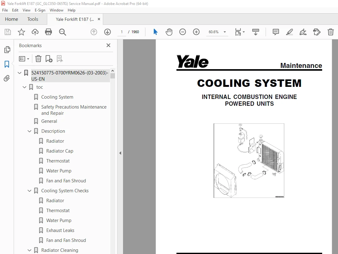
Cooling System 1
Safety Precautions Maintenance and Repair 2
General 5
Description 6
Radiator 6
Radiator Cap 6
Thermostat 6
Water Pump 7
Fan and Fan Shroud 7
Cooling System Checks 7
Radiator 7
Thermostat 7
Water Pump 8
Exhaust Leaks 8
Fan and Fan Shroud 8
Radiator Cleaning 8
Drain 8
Clean 8
Fill 9
Troubleshooting 10
524150790-2100YRM0103-(03-2007)-US-EN 13
toc 13
Tilt Cylinders 13
Safety Precautions Maintenance and Repair 14
General 17
Description 17
Tilt Cylinder Repair 17
Remove 17
Disassemble 17
Clean 17
Assemble 18
Tilt Cylinders With O-Ring or Single-Lip Seals 18
Tilt Cylinders 19
Install 20
Tilt Cylinder Leak Check 22
Tilt Cylinder Stroke and Mast Tilt Angle Adjustment 23
Torque Specifications 23
Piston Rod Nut 23
Retainer 23
Troubleshooting 24
tables 13
Table 1 Movement Rates (Maximum) for Tilt Cylinders 22
524150791-2200YRM0002-(01-2016)-US-EN 29
General 33
Description 34
Alternator Repair 36
Alternator Type A 36
Remove and Disassemble 36
Clean 38
Assemble 38
Install 39
Alternator Type B 42
Remove and Disassemble 42
Clean 42
Assemble 43
Install 44
General Check and Adjustment 44
Low Output Check (Type A or Type B) 45
High Output Check (Type A or Type B) 48
Brushes Circuit Check 49
Delco Alternators 49
Motorola Alternators 49
Diodes Check 50
Diode Bridge Check 50
Delco and Leece-Neville Alternators 50
Motorola Alternators 50
Rotor Field Winding Check 51
Stator Windings Check 52
Voltage Regulator Check 52
Troubleshooting 52
524150792-2200YRM0106-(01-2016)-US-EN 57
General 61
Description and Operation 62
Starter Repair 66
Remove 66
Disassemble 66
Clean 67
Assemble 67
Install 68
General Checks and Adjustments 68
Troubleshooting 70
524150797-8000YRM0231-(02-2023)-US-EN 77
General 83
Threaded Fasteners 83
Nomenclature, Threads 83
Strength Identification 84
Cotter (Split) Pins 85
Fastener Torque Tables 90
Conversion Table 92
524150797-8000YRM0231-(03-2020)-US-EN 99
General 103
Threaded Fasteners 103
Nomenclature, Threads 103
Strength Identification 104
Cotter (Split) Pins 105
Fastener Torque Tables 110
Conversion Table 112
524153914-2200YRM0107-(03-2008)-US-EN 119
toc 119
High Energy Ignition (HEI) System 119
Safety Precautions Maintenance and Repair 120
Description 123
Distributor Repair 125
Remove 125
Disassemble 125
Assemble 131
Install, If Crankshaft WAS NOT Rotated when Distributor was Remo 132
Install, If Crankshaft WAS Rotated when Distributor was Removed 132
Ignition Coil Replacement 134
Some Four- and Six-Cylinder Models 134
Remove 134
Install 134
V8, Some Four- and Six-Cylinder Models 135
Remove 135
Install 135
Electronic Module Replacement 136
Remove 136
Install 136
Sensing Coil Replacement 138
Remove 138
Install 138
Spark Plugs Replacement 138
Remove 138
Install 139
Visual Check 139
High Voltage Wires Check 139
Ignition Coil Check 140
Coil in Distributor Cap Design 140
Separate Coil Design 140
Sensing Coil, Check 141
Electronic Module Check 141
Ignition Timing Adjustment 142
GM V8-366 (6-liter) Ignition System Check 143
GM V6-LPG (4 3 liter) GM V6-LPG (4 3 liter) Ignition Timing and 143
Specifications 143
Troubleshooting 144
524153916-2200YRM0765-(03-2003)-US-EN 149
toc 149
Microprocessor Spark Timing System (MSTS) 149
Safety Precautions Maintenance and Repair 150
General 153
Description 154
What MSTS Does 154
How MSTS Begins Operation 154
Operation 155
Distributor 155
Ignition Coil 156
Ignition Module 156
When Engine Is Being Started 156
When Engine Is Running 158
Manifold Absolute Pressure (MAP) Sensor 159
Engine Coolant Temperature (ECT) Sensor 159
MSTS Module Corrections 160
Troubleshooting 161
General 161
Tools and Test Equipment 163
MSTS 164
Troubleshooting Procedure 164
Where to Start 164
Visual/Physical Inspection 164
Knowledge/Tools Required 164
Damage From Static Discharge (Static Electricity) 165
Troubleshooting Information 165
Malfunction Indicator Lamp (MIL) 165
Connecting CodeMate Tester 165
Reading Diagnostic Trouble Codes (DTC) 166
Clearing Diagnostic Trouble Codes (DTC’s) 167
On-Board Diagnostic (OBD) System Check 167
Test Description 167
No Malfunction Indicator Lamp 169
Circuit Description 169
Test Description 169
No DTC-12, Malfunction Indicator Lamp ON 171
Circuit Description 171
Test Description 171
Starter Rotates Engine, Engine Does Not Run 172
Test Description 172
DTC-14 Engine Coolant Temperature (ECT) (Low Temperature Indicat 176
Circuit Description 176
Test Description 176
DTC-15 Engine Coolant Temperature Sensor (ECT) (High Temperature 178
Circuit Description 178
Test Description 178
DTC-34 Manifold Absolute Pressure (MAP) Sensor 180
Circuit Description 180
Test Description 180
DTC-41 Electronic Spark Timing (EST) Open Circuit 183
Circuit Description 183
Test Description 183
DTC-42 Electronic Spark Timing (EST) Grounded Circuit 185
Circuit Description 185
Test Description 185
DTC-51 MSTS Failure 187
Circuit Description 187
Distributor Repair 187
Remove 187
Disassemble 188
Inspect 188
Assemble 188
Install 189
Ignition Timing 189
Ignition Module Repair 190
Test For Fault 190
Replace 190
Sensing Coil Repair 191
Test For Fault 191
Replace 191
Ignition Coil Repair 192
Test For Fault 192
Remove 192
Install 192
MSTS Module Repair 193
Remove 193
Install 193
ECT Sensor Replacement 193
MAP Sensor Replacement 194
tables 149
Table 1 MSTS Module Connections 162
Table 2 Pressure Conversion Chart 163
Table 3 MSTS Diagnostic Codes 165
524153917-2200YRM0781-(03-2003)-US-EN 197
toc 197
Electronic Engine Control 197
Safety Precautions Maintenance and Repair 198
General 201
Description and Operation 201
General 201
Electronic Control Module (ECM) 201
Diagnostic Connector 201
How ECM Begins Operation 205
Electronic Engine Control 206
What ECM Does 206
Distributor 208
Ignition Module 208
When Engine Is Being Started 209
When Engine Is Running 210
Electronic Control Module (ECM) with Ignition Module Distributor 210
Fuel Control 211
Throttle Body Injection (TBI) 212
Fuel Injectors 212
Fuel Pressure Regulator 212
Throttle Position Sensor (TPS) 213
Idle Air Control (IAC) 213
GM 4 3L Engine Governor System 214
GM 3 0L Engine Governor System 214
Vacuum Ports 216
Fuel Pump 216
ECM Sensors and Controllers 218
Manifold Absolute Pressure (MAP) 218
Engine Coolant Temperature (ECT) Sensor 218
524153918-2200YRM0782-(03-2003)-US-EN 221
toc 221
Electronic Engine Control 221
Safety Precautions Maintenance and Repair 222
General 227
Troubleshooting Procedure 227
How This Section Is Arranged 227
Where Do I Start? 227
Visual/Physical Inspection 227
Knowledge/Tools Required 227
Damage From Static Discharge (Static Electricity) 227
Troubleshooting Information 228
Malfunction Indicator Lamp (MIL) 228
Reading Diagnostic Trouble Codes (DTC) 228
Clearing Diagnostic Trouble Codes (DTCs) 232
ECM Diagnostic Codes Available 233
Diagnostic Mode 233
Field Service Mode 233
ECM Learning Ability 233
SCAN Tool Information 234
On-Board Diagnostic (OBD) System Check 235
Test Description 235
Troubleshooting Charts 237
General 237
Tools and Test Equipment 237
Troubleshooting Chart Description Summary 238
A-1 – No Malfunction Indicator Lamp 238
Circuit Description 238
Test Description 239
Other Troubleshooting Checks 239
A-2 – No Scan Data, No DTC 12, Malfunction Indicator Lamp ON 241
Circuit Description 241
Test Description 241
A-3 – Starter Rotates Engine, Engine Will Not Run 243
Circuit Description 243
Test Description 243
Other Troubleshooting Checks 243
A-4 – Fuel Injector Circuit 245
Test Description 245
A-5 – Fuel Pump Relay Circuit 247
Circuit Description 247
Test Description 247
Other Troubleshooting Checks 247
A-6 – Fuel System Troubleshooting 249
Circuit Description 249
Test Description 249
Other Troubleshooting Checks 249
Test Description 251
Fuel Pressure Check 253
A-7 – Ignition System Troubleshooting 253
Test Description 254
DTC 14 Engine Coolant Temperature Sensor Circuit (Low Temperatur 257
Circuit Description 257
Test Description 257
Other Troubleshooting Checks 257
DTC 15 Engine Coolant Temperature Sensor Circuit (High Temperatu 259
Circuit Description 259
Test Description 259
Other Troubleshooting Checks 259
DTC 21 Throttle Position Sensor Circuit (Signal Voltage High) 261
Circuit Description 261
Test Description 261
Other Troubleshooting Checks 261
DTC 22 Throttle Position Sensor Circuit (Signal Voltage Low) 263
Circuit Description 263
Test Description 263
Other Troubleshooting Checks 263
DTC 31 Engine Governor Circuit 265
Circuit Description 265
Test Description 265
Other Troubleshooting Checks 265
DTC 33 Manifold Absolute Pressure (MAP) Sensor Circuit (Signal V 267
Circuit Description 267
Test Description 267
Other Troubleshooting Checks 267
DTC 34 Manifold Absolute Pressure (MAP) Sensor Circuit (Signal V 269
Circuit Description 269
Test Description 269
Other Troubleshooting Checks 269
DTC 41 Electronic Spark Timing (EST) – Open EST Circuit 271
Circuit Description 271
Test Description 271
Other Troubleshooting Checks 271
DTC 42 EST – Grounded EST Circuit, Open or Grounded Bypass Circu 273
Circuit Description 273
Test Description 274
Other Troubleshooting Checks 274
DTC 51 ECM Failure 276
Circuit Description 276
Other Troubleshooting Checks 276
Troubleshooting, Poor Operation 277
General 277
Make a Careful Visual Check 277
FAULT: Codes or Performance That Is Not Regular 277
FAULT: Loss of Diagnostic Trouble Code (DTC) Memory 277
FAULT: Engine Quits While Driving 277
Additional Checks 277
FAULT: Engine Is Difficult to Start 277
FAULT: Variation in Engine Power When Throttle Is Held Steady 278
FAULT: Decreased Engine Power 278
FAULT: Detonation 279
FAULT: Engine Momentarily Does Not Increase Power When Throttle 279
FAULT: One or More Cylinders Do Not Operate Correctly – Engine D 280
FAULT: Rough Idle or Engine Stalls During Idle 280
FAULT: Fuel Usage Too High 280
FAULT: Dieseling 281
FAULT: Backfire 281
System Test Charts 281
General 281
Engine Coolant Temperature (ECT) Sensor Test 281
Throttle Position (TP) Sensor Check 282
Minimum Idle Speed 282
Adjustment 283
B-1 – Idle Air Control (IAC) System Check 284
Circuit Description 284
Other Troubleshooting Checks 284
B-2 – Manifold Absolute Pressure (MAP) Sensor Output Test 286
Circuit Description 286
Test Description 286
B-3 – Check Governor System 288
Governor System Not Operating Correctly 288
Check Function of Governor System 288
Check PCV System 289
Fuel System Components Repair 289
General 289
Fuel Pressure Relief Procedure 289
Fuel Pump Replacement 289
Throttle Body Injection Unit (TBI) 290
Remove 290
Clean and Inspect 291
Install 291
Fuel Meter Body 291
Remove 291
Install 294
Fuel Injector 294
Remove 294
Install 295
Pressure Regulator 295
Remove 295
Inspect 295
Install 295
Throttle Position Sensor (TPS) 296
Remove 296
Install 296
Idle Air Control (IAC) Valve 296
Remove 296
Clean and Inspect 296
Install 297
Governor System 3 0L Engine Repair 297
Governor Module, Replace 297
Governor Motor, Replace 297
Throttle Cables, Install and Adjust 297
Foot Directional Control Pedal, Check 298
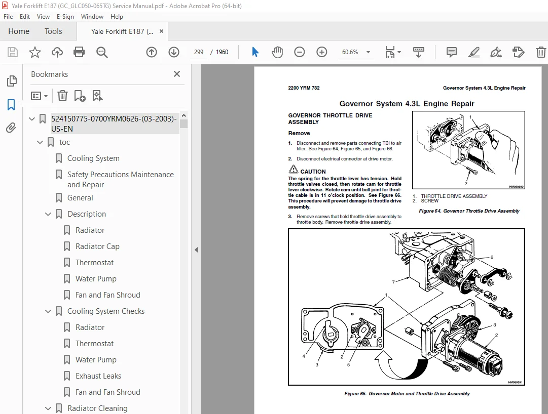
Governor System 4 3L Engine Repair 299
Governor Throttle Drive Assembly 299
Remove 299
Inspect 300
Install 300
Governor Drive Motor 300
Remove 300
Clean and Lubricate 300
Install 301
Inspect 302
Ignition System Components Repair 302
ECM Replacement 302
Function Check 302
Distributor 302
Remove 302
Disassemble 302
Inspect 303
Assemble 303
Install 303
Firing Order 304
Ignition Timing 304
Ignition Module Repair 304
Test For Fault 304
Replace 305
Sensing Coil 305
Test 305
Replace 306
Ignition Coil 306
Test 306
Remove 306
Install 307
Sensors Repair 307
Engine Coolant Temperature (ECT) Sensor, Replace 307
MAP Sensor, Replace 307
PCV System Repair 308
Replace 308
Wiring 308
Connectors and Terminals 308
Procedures for Spark Plugs, Spark Plug Wires, and Boots 311
Wiring Diagram 311
Spark Plugs Troubleshooting 316
Special Tools 317
tables 221
Table 1 ECM Diagnostic Codes Available 233
Table 2 SCAN Tool Information 234
Table 3 Troubleshooting Chart Description Summary 238
Table 4 ECT Sensor – Temperature vs Resistance 259
Table 5 ECT Sensor – Temperature vs Resistance 282
Table 6 ECM Connector J1 Identification 314
Table 7 ECM Connector J2 Identification 315
524158636-0100YRM0505-(06-2004)-US-EN 321
toc 321
Frame 321
Safety Precautions Maintenance and Repair 322
General 325
Description 325
Operator Module Repair 325
Remove 325
Install 325
Hood and Side Covers Repair 327
Remove 327
Install and Adjust 327
Overhead Guard Repair 329
Remove and Install 329
LED Backup and Brake Lights, Replace 330
Remove 330
Install 330
Counterweight Repair 331
Remove 331
Install 332
Exhaust System Repair 333
Muffler, Replace 334
Radiator and Cooling System Repair 340
Remove 340
Install 340
Operator Restraint System Repair 342
Engine Repair 343
Remove Engine Only 343
Remove Engine and Transmission 343
Install Engine Only 344
Install Engine and Transmission 345
Fuel and Hydraulic Tanks Repair 345
Inspect 345
Small Leaks, Repair 345
Large Leaks, Repair 345
Clean 346
Steam Method of Cleaning 346
Chemical Solution Method of Cleaning 346
Additional Preparations for Repair 346
Safety Labels 347
tables 321
Table 1 Weight of Counterweights 332
524158637-0600YRM1020-(10-2006)-US-EN 353
toc 353
GM Engine Repair 353
Safety Precautions Maintenance and Repair 354
General 357
Description 357
Engine Removal and Installation 365
Cylinder Head and Valve Mechanism Repair 365
Cylinder Head, Remove 365
Cylinder Head, Disassemble 367
Clean and Inspect 367
Valves and Valve Seats 370
Studs for Rocker Arms 370
Hydraulic Valve Lifters 371
Replace 371
Clean and Inspect 371
Cylinder Head, Assemble 371
Cylinder Head, Install 372
Valve Clearance, Adjust 373
Rocker Arm Cover, Install 373
Timing Gear Cover Repair 374
Remove 374
Install 374
Timing Wheel Repair 375
Timing Wheel, Removal 375
Timing Wheel, Install 375
Air Gap Adjustment 376
Camshaft Repair 378
Camshaft, Remove 378
Camshaft, Clean and Inspect 378
Camshaft Bearings, Remove 380
Camshaft Bearings, Clean and Inspect 380
Camshaft Bearings, Install 380
Camshaft, Install 381
Distributor Repair 381
Remove 381
Install 382
Lubrication System Repair 383
Oil Pan 383
Remove 383
Install 383
Oil Pump 383
Remove 383
Disassemble 384
Clean and Inspect 385
Assemble 385
Install 385
Piston and Piston Rod Assemblies Repair 385
Piston Rod Bearings, Replace 385
Piston and Piston Rod Assemblies, Remove 387
Piston and Piston Rod Assemblies, Disassemble 387
Pistons, Clean and Inspect 388
Cylinder Bores, Inspect and Repair 388
Piston Rings, Inspect 389
Piston and Piston Rod Assemblies, Assemble 390
Piston and Piston Rod Assemblies, Install 390
Crankshaft Repair 391
Main Bearings, Replace 391
Oil Seal for Rear Main Bearing, Replace 392
Crankshaft, Remove 392
Inspect and Repair 393
Main Bearing and Journal Clearance, Check 394
Crankshaft, Install 395
Flywheel and Flywheel Housing Repair 395
Flywheel, Remove 396
Ring Gear, Replace 397
Flywheel, Install 397
Cooling System Repair 397
Water Pump 397
Remove 397
Inspect 397
Install 398
Thermostat 398
Remove and Install 398
Alternator Repair 398
Starter Repair 398
Checks and Adjustments 400
Engine Compression Test 400
Test Procedure 400
Test Results 400
Engine Noise Diagnostic Test 400
Description 400
Test Procedure 400
Engine Specifications 402
Engine Data 402
Cylinder Bore 402
Piston 402
Piston Rings 402
Wrist Pin 403
Crankshaft 403
Piston Rod 404
Camshaft 404
Hydraulic Valve System 404
Cylinder Head Warpage 405
Lubrication System 405
Cooling System 405
Torque Specifications 406
Troubleshooting 407
524158742-0600YRM0496-(01-2011)-US-EN 413
toc 413
Mazda Engine 413
Safety Precautions Maintenance and Repair 414
General 417
Description 417
Engine Removal and Installation 417
Cylinder Head, Camshaft, and Valve Mechanism Repair 418
Remove 418
Clean 419
Inspect and Repair 420
Cylinder Head 420
Rocker Shaft Assembly 420
Camshaft 420
Valve Guides 421
Valve Seats 422
Valves 422
Valve Springs 423
Install 423
Crankshaft and Main Bearings Repair 426
Remove 426
Inspect and Repair 426
Crankshaft 426
Main Bearings 426
Install 427
Pistons and Connecting Rods Repair 428
Remove and Disassemble 428
Clean 428
Inspect and Repair 428
Pistons 428
Piston Rings 429
Connecting Rods and Bearings 429
Assemble and Install 430
Cylinder Block Repair 431
Oil Pump Repair 431
Remove 431
Disassemble 432
Clean 432
Inspect 432
Assemble 433
Install 434
Cooling System Repair 434
Thermostat 434
Replace 434
Fan Assembly 434
Remove and Disassemble 434
Assemble and Install 435
Water Pump 435
Remove and Disassemble 435
Assemble and Install 436
Distributor Repair 437
Remove 437
Install 437
Flywheel and Ring Gear Repair 438
Remove 438
Ring Gear, Replace 438
Install 438
Flywheel Repair 439
Remove 439
Install 439
Valve Adjustment 440
Compression Pressure Check 440
Engine Timing Adjustment 441
Throttle Linkage Adjustment 441
Gasoline Engines 441
LPG Engines (IMPCO) 441
LPG Engines (AISAN) 442
Engine Specifications 442
Engine Data 442
Thermostat 442
Cylinder Head 442
Valve Mechanism 442
Camshaft 443
Crankshaft 443
Connecting Rods 444
Cylinder Block 444
Pistons 444
Oil Pump 444
Torque Specifications 445
Troubleshooting 446
524158744-0900YRM0498-(12-2003)-US-EN 451
toc 451
LPG Fuel System 451
Safety Precautions Maintenance and Repair 452
General 455
Description and Operation 455
Fuel Tank 456
Fuel Filter and Fuel Valve Unit 456
Vaporizer 456
Carburetor 458
Solenoid Valve 459
Idle Control Actuator 460
Governor System 460
Hose Replacement 460
LPG Tank Repair 461
Remove 461
Install 461
Hydrostatic Relief Valve Repair 462
Remove and Install 462
Filter Unit Repair 462
Fuel Filter Element, Replace 462
Diaphragm and Fuel Valve, Replace 464
Vaporizer Repair 464
Remove 464
Disassemble 464
Clean 464
Inspect 464
Assemble 466
Install 470
Carburetor Repair 470
Remove 470
Disassemble 470
Clean 470
Assemble 472
Install 472
Solenoid Valve Repair 472
Governor System Check 473
Filter Unit Check 473
Vaporizer Check 474
Pressure Reducer Valve 474
Vapor Valve 474
Carburetor Adjustment 474
Idle, Adjust 474
Power Mixture 475
Throttle Linkage Adjustment 476
Foot Directional Control Pedal, Check 477
Troubleshooting 478
524158745-0900YRM0502-(12-2003)-US-EN 485
toc 485
Gasoline Fuel System 485
Safety Precautions Maintenance and Repair 486
General 489
Description 489
Carburetor 489
Governor 490
Carburetor Operation 490
Float System 490
Idle System 491
Idle Control Actuator 491
Idle Compensator Valve 491
Idle Metering System 491
Solenoid Valve (Shutoff Valve) 492
Main Metering System 492
Choke System 492
Vacuum Diaphragm 493
Temperature Sensor System 493
Choke-Release Mechanism 493
Power System 493
Accelerator Pump System 493
Governor Operation 494
Governor Repair 494
Carburetor Repair 494
Remove 494
Disassemble 495
Clean 495
Inspect 497
Assemble 497
Install 498
Carburetor Adjustment 499
Idle Speed and Mixture, Adjust 499
Throttle Linkage Adjustment 500
Foot Directional Control Pedal, Check 501
Governor Adjustment 502
Troubleshooting 503
524158746-0900YRM0523-(12-2003)-US-EN 509
toc 509
LPG Fuel System 509
Safety Precautions Maintenance and Repair 510
General 513
Description and Operation 513
Fuel Tank 515
Fuel Filter and Fuel Valve Unit 515
Vaporizer 516
Carburetor 518
Solenoid Valve 520
Idle Control Actuator 520
Governor 520
Hose Replacement 520
LPG Tank Repair 521
Remove 521
Install 521
Hydrostatic Relief Valve Repair 522
Remove and Install 522
Filter Unit Repair 522
Fuel Filter Element, Replace 522
Diaphragm and Fuel Valve, Replace 524
Vaporizer Repair 524
Remove 524
Disassemble 524
Clean 524
Inspect 524
Assemble 526
Install 529
Carburetor Repair 530
Remove 530
Disassemble 530
Clean 530
Assemble 533
Install 533
Solenoid Valve Repair 533
Governor Repair 533
Filter Unit Check 534
Vaporizer Check 534
Pressure Reducer Valve 534
Vapor Valve 534
Carburetor Adjustment 534
Idle Mixture 534
Idle, Adjust 534
Power Mixture, Adjust 535
Governor Check and Adjustment 536
Check 536
Adjust 536
Throttle Linkage Adjustment GC/GLC040-065RG/TG/ZG and GP/GLP/GDP 537
Throttle Linkage Adjustment GP/GLP/GDP16-20AF/BF (GP/GLP/GDP030- 538
Foot Directional Control Pedal Check 539
Troubleshooting 540
524158747-0900YRM0925-(12-2003)-US-EN 547
toc 547
LPG Fuel System 547
Safety Precautions Maintenance and Repair 548
General 551
Description and Operation 551
Fuel Tank 552
Regulator 552
Start Mode 554
Idle Mode 554
Run Mode 554
Resonator 554
Carburetor 555
Start Mode 555
Idle Mode 555
Run Mode 555
Governor 556
Hoses Replacement 557
LPG Tank Repair 557
Remove 557
Install 557
Relief Valve Repair 558
Remove and Install 558
Carburetor Repair 558
Remove 558
Disassemble 558
Clean 559
Assemble 559
Install 560
Governor Repair 560
Remove 560
Inspect 560
Install 560
Regulator Repair 561
Remove 561
Disassemble 561
Clean 561
Inspect 561
Assemble 563
Install 564
Regulator Adjustment 564
Regulator Height Adjustment 564
Regulator Assembly Air Tightness Test 565
Carburetor Adjustment 566
Idle Speed and Fuel Mixture 566
Idle Control Adjustment 566
Governor Adjustment 567
Checks 567
Adjustments 567
Throttle Linkage Adjustment 568
Foot Directional Control Pedal Check 569
Throttle Linkage Adjustment 570
Troubleshooting 571
tables 547
Table 1 Power Adjusting Screw 560
Table 2 Air Adjusting Screw 560
Table 3 Idle Mixture Adjusting Screw 563
Table 4 Idle Mixture Adjusting Screw 566
524158748-0900YRM0948-(10-2006)-US-EN 579
toc 579
LPG Fuel System 579
Safety Precautions Maintenance and Repair 580
General 583
Description and Operation 583
Fuel Tank 583
Oxygen Sensor 583
Regulator 583
Start Mode 586
Idle Mode 589
Run Mode 589
Resonator 589
Carburetor 589
Start Mode 589
Idle Mode 590
Run Mode 590
Governor 591
Hoses Replacement 591
LPG Tank Repair 592
Remove 592
Install 592
Relief Valve Repair 593
Remove and Install 593
Carburetor Repair 593
Remove 593
Disassemble 593
Clean 594
Assemble 594
Install 595
Fuel Injector Repair 595
Remove 595
Clean and Inspect 595
Install 595
Governor Repair 596
Remove 596
Inspect 596
Install 596
Regulator Repair 596
Remove 596
Install 596
Oxygen Sensor Repair 596
Remove and Install 596
Vacuum Switches Repair 597
Remove and Install 597
Inspect 597
Resistor Repair 597
Remove and Install 597
Inspect 597
Carburetor and New Regulator Adjustment 597
Idle Speed and Fuel Mixture 597
Idle Control Adjustment 598
Governor Checks and Adjustments 599
Checks 599
Adjustments 599
Throttle Linkage Adjustment 599
Foot Directional Control Pedal Check 601
Check Engine Light 601
Inspect Warning Lamp 601
Check Feedback Operation 601
Check VAC1 and VAC2 Signals 601
Check Resistor 601
Check Fuel Injector 601
Check Oxygen Sensor 602
Check Vacuum Switch 1 602
Check Vacuum Switch 2 602
After Completing Checks 602
Troubleshooting 602
tables 579
Table 1 Adjusting Screw 595
524158749-1300YRM0500-(08-2003)-US-EN 611
toc 611
Single-Speed Powershift Transmission 611
Safety Precautions Maintenance and Repair 612
General 615
Description and Operation 615
General 615
Torque Converter 616
Description 616
Operation 616
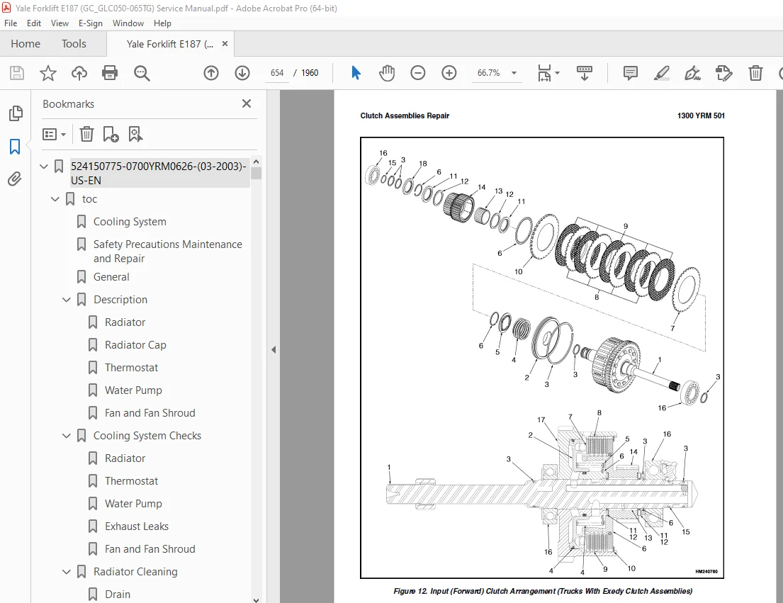
Clutch Assemblies 618
Description 618
Operation 619
Hydraulic System 622
General 622
Control Valve 623
General 623
Clutch Pressure Regulator 624
Inching Spool Assembly 625
Direction Spool 625
Modulator Circuit 625
Torque Converter Regulator 625
Foot Directional Control Pedal 625
Foot Directional Control Pedal Start Circuit 626
Direction Control Lever 626
Differential 626
Oil Flow Diagrams 628
Neutral 628
Modulator Operation 628
Forward 632
Forward-Inching 632
524158750-1300YRM0501-(03-2004)-US-EN 639
toc 639
Single-Speed Powershift Transmission 639
Safety Precautions Maintenance and Repair 640
General 643
Transmission Removal 647
Torque Converter and Housing Repair 647
Remove 647
Install 647
Transmission Pump Repair 649
Remove 649
Repair 649
Install 649
Front Cover and Pump Drive Repair 649
Remove and Disassemble 649
Assemble and Install 649
Clutch Assemblies Repair 652
Remove and Disassemble 655
Inspect 657
Assemble 658
Install 663
Differential Repair 664
Remove and Disassemble 664
Inspect 665
Assemble and Install 666
Control Valve Repair 673
Remove and Disassemble 673
Inspect 673
Assemble and Install 673
Foot Directional Control Pedal Repair 676
Remove and Disassemble 676
Assemble and Install 676
Direction Control Lever Repair 679
Remove and Disassemble 679
Assemble and Install 679
Stall Test 680
Inching/Brake Pedal Adjustment 681
Neutral Start Switch, Foot Directional Control Pedal Adjustment 685
Neutral Start Switch, Foot Directional Control Pedal Adjustment 686
Neutral Start Switch Test, Foot Directional Control Pedal 687
Oil Pressure Checks 687
Relief Valve for Transmission Pump Check, TEST PORT 1 687
Clutch Pressure Check, TEST PORTS 2 and 3 687
Torque Converter Regulator Check, TEST PORT 4 688
Lubrication Circuit Oil Pressure Check, TEST PORT 5 688
Modulator Pressure Check, TEST PORT 6 688
Troubleshooting 689
Troubleshooting – Pressure Tests 692
tables 639
Table 1 Adjustment of Shims for Pinion Assembly 666
Table 2 Ring and Pinion Tooth Contact Adjustment 667
Table 3 Stall Speeds 681
Table 4 Transmission Oil Pressures Test Ports 688
524158751-1400YRM0499-(10-2004)-US-EN 697
toc 697
Drive Axle 697
Safety Precautions Maintenance and Repair 698
General 701
Description 701
Drive Axle Repair 701
Remove and Disassemble 701
Clean and Inspect 703
Assemble and Install 703
Torque Specifications 705
GP2 00-3 00RF/TF (GP040-060RG/TG/ZG) 705
GC040-065TF/RF 705
Troubleshooting 706
524158753-1600YRM0720-(11-2006)-US-EN 709
toc 709
Steering Housing and Control Unit 709
Safety Precautions Maintenance and Repair 710
General 713
Description 713
Operation 714
Steering Wheel and Column Assembly Repair 715
Assembly Components, Remove 715
Steering Control Unit, Disassemble 720
Steering Control Unit, Clean 720
Steering Control Unit, Assemble 720
Assembly Components, Install 722
System Air Removal 724
Troubleshooting 724
524158754-1800YRM0506-(05-2005)-US-EN 729
toc 729
Brake System 729
Safety Precautions Maintenance and Repair 730
General 733
Description and Operation 733
Service Brakes 733
Master Cylinder 733
Parking Brake 735
Service Brakes Repair 735
Remove and Disassemble 735
Clean 737
Inspect 737
Assemble and Install 739
Adjust 743
Parking Brake Repair 743
Remove and Disassemble 743
Assemble and Install 743
Adjust 743
Master Cylinder Repair 745
Remove 745
Clean and Inspect 745
Repair 746
Install 748
Service Brakes Adjustment 748
Brake System Air Removal 749
Parking Brake Not Applied Switch Test 749
Parking Brake Switch Test (Foot Directional Control Pedal Only) 749
Inching/Brake Pedal Adjustment 750
Neutral Start Switch Adjustment, Foot Directional Control Pedal 754
Neutral Start Switch Adjustment, Foot Directional Control Pedal 755
Neutral Start Switch Test (Foot Directional Control Pedal) 756
Torque Specifications 756
GP2 00-3 00RF/TF (GP040-060RG/TG/ZG) 756
GC040-065RG/TG/ZG 756
Troubleshooting 756
524158755-1900YRM0513-(06-2004)-US-EN 763
toc 763
Hydraulic System 763
Safety Precautions Maintenance and Repair 764
General 767
Description 767
Hydraulic System 767
Gear Pump Assembly 767
Flow Control Valve 767
Relief Valve 767
Operation 774
Hydraulic System 774
Gear Pump 774
Flow Control Valve 774
Relief Valve 774
Gear Pump Assembly Repair 776
Remove and Disassemble 776
Assemble and Install 777
Steering Relief Pressure Check and Adjustment 777
Gear Pump Flow Check 778
Troubleshooting 778
524158756-2000YRM0516-(12-2003)-US-EN 783
toc 783
Main Control Valve 783
Safety Precautions Maintenance and Repair 784
General 787
Description 787
Operation 788
Lift Section 788
Tilt Section 788
Tilt Backward 788
Tilt Forward 788
Relief Valve 792
Main Control Valve Repair 793
Remove 793
Disassemble 793
Clean and Inspect 793
Assemble 793
Install 799
Pressure Relief Valve Check and Adjustment 800
Primary Relief Valve 800
Secondary Relief Valve 800
Troubleshooting 801
524158757-2200YRM0514-(01-2004)-US-EN 805
toc 805
Instrument Cluster 805
Safety Precautions Maintenance and Repair 806
General 809
Description 809
Instrument Cluster Display Panel, Internal Combustion Lift Truck 809
Instrument Cluster Display Panel, Electric Lift Truck Models 816
Optional Basic Display Panel 816
Features of the Optional Basic Display Panel 816
Description of Features on the Optional Basic Display Panel 816
Standard Display Panel 817
Features of the Standard Display Panel 817
Description of Features on the Standard Display Panel 817
Premium Display Panel 818
Features on the Premium Display Panel 818
Description of Features on the Premium Display Panel 819
Curtis 1215 Display Panel 821
Description and Features 821
Operation 822
Cluster-Type Display Panel (Internal Combustion) Replacement 823
Remove 823
Install 823
Cluster Display Panel (Electric Lift Truck) Replacement 826
Curtis 1215 Display Panel Replacement 831
Remove 831
Install 831
tables 805
Table 1 Instrument Cluster, Internal Combustion 810
524158758-2200YRM0524-(12-2003)-US-EN 835
toc 835
Electrical System 835
Safety Precautions Maintenance and Repair 836
General 839
Description 839
Starting System 839
Ignition System 839
Charging System 840
Starter Repair 841
Remove and Disassemble 841
Assemble and Install 841
Coil Replacement 843
Distributor Repair 844
Remove and Disassemble 844
Assemble and Install 844
Distributor Repair 846
Remove and Disassemble 846
Assemble and Install 848
Alternator Repair 848
Remove and Disassemble 848
Assemble and Install 849
General Checks and Adjustments 850
Starter Checks 850
Operation, Check 850
Brush Holder, Check 851
Armature, Check 851
Field Windings, Check 851
Clutch and Bearing, Check 851
Ignition System Check and Adjustment 852
Engine Timing, Adjust 852
Spark Plugs, Check 852
Charging Circuit Checks 853
Low Output, Check 853
High Output, Check 854
Diodes, Check 854
Rotor Field Winding, Check 855
Stator Windings, Check 855
Brushes and Bearings, Check 855
Voltage Regulator, Check 855
Troubleshooting 856
524158759-2200YRM0603-(12-2003)-US-EN 861
toc 861
Microprocessor Spark Timing System (MSTS) 861
Safety Precautions Maintenance and Repair 862
General 865
Description 865
What MSTS Does 865
How MSTS Begins Operation 865
Operation 866
Distributor 866
Ignition Module 867
When Engine is Being Started 868
When Engine is Running 868
Manifold Absolute Pressure (MAP) Sensor 869
Engine Coolant Temperature (ECT) Sensor 870
MSTS Module Corrections 870
Initial Timing Connector 872
Governor System Operation 872
Troubleshooting 874
General 874
Tools and Test Equipment 875
MSTS 875
Test Description 875
Ignition System 877
Test Description 877
Electronic Spark Timing (EST) 880
Circuit Description 880
Test Description 881
Manifold Absolute Pressure (MAP) Sensor 884
Circuit Description 884
Test Description 884
Test 1 885
Test 2 886
Engine Coolant Temperature (ECT) Sensor 887
Circuit Description 887
Test Description 887
Distributor Repair 889
Remove 889
Disassemble 889
Inspect 890
Assemble 890
Install 890
Ignition Timing 890
Ignition Module Replacement 891
Test for a Fault 891
Replace 892
Sensing Coil Replacement 892
Test for a Fault 892
Replace 892
Ignition Coil Replacement 893
Test for a Fault 893
Remove 893
Install 893
MSTS Module Replacement 894
Remove 894
Install 894
ECT Sensor Replacement 894
MAP Sensor Replacement 895
tables 861
Table 1 MSTS Module Connections 872
Table 2 Voltage and Pressure for MAP Sensor Troubleshooting 885
Table 3 Pressure Conversion Chart 886
524158885-2200YRM0611-(12-2003)-US-EN 899
toc 899
Electronic Engine Control 899
Safety Precautions Maintenance and Repair 900
General 905
Troubleshooting Procedure 905
Where Do I Start? 905
Visual/Physical Inspection 905
Knowledge/Tools Required 905
Damage From Static Discharge (Static Electricity) 905
Troubleshooting Information 905
Malfunction Indicator Lamp (MIL) 906
Reading Diagnostic Trouble Codes (DTCs) 906
Clearing Diagnostic Trouble Codes (DTC’s) 907
Diagnostic Mode 907
Field Service Mode 907
ECM Learning Ability 908
On-Board Diagnostic (OBD) System Check 908
Troubleshooting Charts 911
Tools and Test Equipment 911
A-1 – No Malfunction Indicator Lamp 912
Circuit Description 912
Test Description 912
Other Troubleshooting Checks 912
A-2 – No SCAN Data, No DTC 12, Malfunction Indicator Lamp On 915
Circuit Description 915
Test Description 915
A-3 – Starter Rotates the Engine, Engine Will Not Run 917
Circuit Description 917
Test Description 917
Other Troubleshooting Checks 918
A-4 – Fuel Injector Circuit 920
Circuit Description 920
Test Description 920
A-5 – Fuel Pump Relay Circuit 922
Circuit Description 922
Test Description 922
Other Troubleshooting Checks 922
A-7 – Fuel System Troubleshooting 924
Circuit Description 924
Test Description 925
Other Troubleshooting Checks 925
Test Description 925
Fuel Pressure Check 928
A-8 Ignition System Troubleshooting 929
Test Description 929
DTC 14 – Engine Coolant Temperature Sensor Circuit (High Tempera 933
Circuit Description 933
Test Description 933
Other Troubleshooting Checks 933
DTC 15 – Engine Coolant Temperature Sensor Circuit (Low Temperat 935
Circuit Description 935
Test Description 935
Other Troubleshooting Checks 935
DTC 21 – Throttle Position Sensor Circuit (Signal Voltage High) 937
Circuit Description 937
Test Description 937
Other Troubleshooting Checks 937
DTC 22 – Throttle Position Sensor Circuit (Signal Voltage Low) 939
Circuit Description 939
Test Description 939
Other Troubleshooting Checks 939
DTC 31 – Engine Governor Circuit 941
Circuit Description 941
Test Description 941
Other Troubleshooting Checks 941
DTC 33 – Manifold Absolute Pressure (MAP) Sensor Circuit (Signal 943
Circuit Description 943
Test Description 943
Other Troubleshooting Checks 943
DTC 34 – Manifold Absolute Pressure (MAP) Sensor Circuit (Signal 945
Circuit Description 945
Test Description 945
Other Troubleshooting Checks 945
DTC 42 – Electronic Spark Timing (EST) 947
Circuit Description 947
Test Description 948
Other Troubleshooting Checks 948
DTC 51 – ECM Failure 950
Circuit Description 950
Other Troubleshooting Checks 950
Troubleshooting, Poor Operation 950
General 950
Make a Careful Visual Check 950
FAULT: Codes or Performance That is Not Regular 950
Definition: 950
Check: 951
FAULT: Loss Of Diagnostic Trouble Code (DTC) Memory 951
FAULT: Engine Quits While Driving 951
Additional Checks 951
FAULT: Engine Is Difficult To Start 951
Definition: 951
Check: 951
FAULT: Variation In Engine Power When The Throttle Is Held Stead 952
Definition: 952
Check: 952
FAULT: Decreased Engine Power 952
Definition: 952
Check: 952
FAULT: Detonation 952
Definition: 952
Check: 952
FAULT: Engine Momentarily Does Not Increase Power When Throttle 953
Definition: 953
Check: 953
FAULT: One Or More Cylinders Do Not Operate Correctly The Engin 953
Definition: 953
Check: 953
FAULT: Rough Idle Or Engine Stalls During Idle 954
Definition: 954
Checks: 954
FAULT: Fuel Usage Too High 954
Definition: 954
Check: 954
FAULT: Dieseling 954
Definition: 954
Checks: 955
FAULT: Backfire 955
Definition: 955
Check: 955
Engine Coolant Temperature (ECT) Sensor Test 955
Throttle Position (TP) Sensor Check 956
Minimum Idle Speed Adjustment 957
Adjust 957
C-1 – Idle Air Control (IAC) System Check 958
Circuit Description 958
Other Troubleshooting Checks 958
C-2 – Manifold Absolute Pressure (MAP) Sensor Output Test 960
Circuit Description 960
Test Description: 960
PCV System Check 962
Governor System Check 962
Governor System Not Operating Correctly 962
Governor System Function, Check 963
Fuel System Components Repair 963
General 963
Fuel Pressure Relief Procedure 963
Fuel Pump, Replace 963
TBI Unit 964
Remove 964
Clean and Inspect 965
Install 965
Fuel Meter Body 966
Remove 966
Install 966
Fuel Injector 967
Remove 967
Install 967
Pressure Regulator 968
Remove 968
Inspect 968
Install 968
Throttle Position Sensor (TPS) 968
Remove 968
Install 968
Idle Air Control (IAC) Valve 969
Remove 969
Clean and Inspect 969
Install 969
Throttle Body 970
Remove and Disassemble 970
Inspect 970
Assemble and Install 970
Oil Pressure Switch, Replace 970
Governor System Repair 972
Governor Module, Replace 972
Governor Motor, Replace 972
Throttle Cables, Install and Adjust 973
Foot Directional Control Pedal, Check 974
Ignition System Components Repair 974
ECM, Replace 974
Function, Check 974
Distributor 974
Remove 974
Disassemble 975
Inspect 975
Assemble 975
Install 976
Ignition Timing 976
Ignition Module Repair 976
Test For a Fault 976
Ignition Module, Replace 977
Sensing Coil 978
Test 978
Replace 978
Ignition Coil 978
Test 978
Remove 979
Install 979
Sensors Repair 979
Engine Coolant Temperature (ECT) Sensor, Replace 979
MAP Sensor Replacement 979
PCV System Repair 980
Replace 980
Wiring Repair 980
Connectors and Terminals 980
Procedures for Spark Plugs, Spark Plug Wires, and Boots 983
Spark Plug Troubleshooting 984
Wiring Diagrams 985
Special Tools 990
tables 899
Table 1 ECM Diagnostic Codes Available 907
Table 2 SCAN Tool Information 909
Table 3 ECT Sensor – Temp vs Resistance 933
Table 4 ECT Sensor – Temp vs Resistance 935
Table 5 ECM Failure 950
Table 6 ECT Sensor – Temperature vs Resistance 955
524158887-2200YRM0612-(12-2003)-US-EN 995
toc 995
Electronic Engine Control 995
Safety Precautions Maintenance and Repair 996
General 999
Description and Operation 999
General 999
Electronic Control Module (ECM) 999
How ECM Begins Operation 1001
Electronic Engine Control 1001
What ECM Does 1001
Distributor 1002
Ignition Module 1002
When the Engine is Being Started 1003
When the Engine is Running 1004
Electronic Control Module (ECM) Corrections 1004
What the ECM Does 1005
Fuel Control Operation 1005
Starting Mode 1005
Clear Excess Fuel (clear flood) Mode 1005
Run Mode 1006
Acceleration Mode 1006
Deceleration Mode 1006
Fuel Cutoff Mode 1006
Fuel System Components 1006
Fuel Pump Electrical Circuit 1006
Throttle Body Injection 1006
Throttle Position (TP) Sensor 1006
Idle Air Control (IAC) Valve 1007
Fuel Injector 1008
Fuel Pressure Regulator 1008
Idle Speed Control 1008
Maximum RPM Control 1008
Governor System 1008
ECM Sensors and Controllers 1009
Manifold Absolute Pressure (MAP) Sensor 1009
Engine Coolant Temperature (ECT) Sensor 1010
Positive Crankcase Ventilation 1010
524158890-4000YRM0521-(03-2006)-US-EN 1013
toc 1013
Mast 1013
Safety Precautions Maintenance and Repair 1014
General 1017
Description and Operation 1017
Carriages 1017
Mast Mounts 1019
Two-Stage Mast, Limited Free-Lift (LFL) 1020
Description and Operation 1020
Two-Stage Mast, Full Free-Lift (FFL) 1022
Description and Operation 1022
Three-Stage Mast, Full Free-Lift (FFL) 1024
Description and Operation 1024
Four-Stage Mast 1026
Description and Operation 1026
Cylinder Cushion During Lifting Sequence 1030
Cylinder Cushion During Lowering Sequence 1031
524158891-4000YRM0522-(07-2010)-US-EN 1035
toc 1035
Mast 1035
Safety Precautions Maintenance and Repair 1036
General 1039
Safety Procedures When Working Near Mast 1040
Fork Repair 1042
Remove 1042
Install 1042
Carriages Repair 1044
Standard Carriage, Remove 1044
Hang-On Sideshift Carriage, Remove 1045
Standard Carriage and Hang-On Sideshift Carriage, Repair 1046
Standard Carriage, Install 1047
Hang-On Sideshift Carriage, Install 1048
Integral Sideshift Carriage 1048
Remove 1048
Clean and Inspect 1052
Repair 1053
Install 1054
Mast Repair 1055
Remove 1055
Two-Stage LFL and Two-Stage FFL Masts, Disassemble 1057
Three-Stage FFL Mast 1065
Disassemble 1065
Mast and Chains, Clean and Inspect 1068
Two-Stage LFL and Two-Stage FFL Mast, Assemble 1069
Three-Stage FFL Mast, Assemble 1070
Install 1071
Lift Cylinders Repair 1073
Main Lift Cylinders, Remove 1073
Free-Lift Cylinder, Remove 1073
Cylinders, Disassemble 1074
Two-Stage Full Free-Lift Mast, Right-Hand Main Lift Cylinder 1074
Two-Stage Full Free-Lift Mast, Left-Hand Main Lift Cylinder 1076
Two-Stage Limited Free-Lift Mast and Three-Stage Full Free-Lift 1076
Two-Stage Limited Free-Lift Mast and Three-Stage Full Free-Lift 1077
Two-Stage Full Free-Lift Mast and Three-Stage Full Free-Lift Mas 1078
Clean and Inspect 1079
Cylinders, Assemble 1079
Two-Stage Full Free-Lift Mast, Right-Hand Main Lift Cylinder 1079
Two-Stage Full Free-Lift Mast, Left-Hand Main Lift Cylinder 1080
Two-Stage Limited Free-Lift Mast and Three-Stage Full Free-Lift 1081
Two-Stage Limited Free-Lift Mast and Three-Stage Full Free-Lift 1081
Two-Stage Full Free-Lift Mast and Three-Stage Full Free-Lift Mas 1082
Main Lift Cylinders, Install 1083
Free-Lift Cylinder, Install 1083
Header Hose Arrangements 1084
Two-Stage LFL Mast, New Hose Install 1084
Two-Stage LFL Mast, Adjust Hoses After Installation 1089
Two-Stage FFL Mast, New Hose Install 1089
Two-Stage FFL Mast, Adjust Hoses After Installation 1097
Three-Stage FFL Mast, New Hose Install 1097
Three-Stage FFL Mast, Adjust Hoses After Installation 1108
Header Hose Arrangement 1109
Two-Stage LFL Mast, New Hose Install 1109
Two-Stage LFL Mast, Adjust Hoses After Installation 1114
Two-Stage FFL Mast, New Hose Install 1114
Two-Stage FFL Mast, Adjust Hoses After Installation 1120
Three-Stage FFL Mast, New Hose Install 1120
Three-Stage FFL Mast, Adjust Hoses After Install 1129
Lift and Tilt System Leak Check 1130
Lift Cylinders Leak Check 1130
Tilt Cylinders Leak Check 1130
Tilt Cylinders Adjustment 1131
Lift Chains Adjustment 1133
Mast Adjustment 1135
Carriage Adjustment 1137
Troubleshooting 1138
tables 1035
Table 1 Hook-Type Carriage Chain Adjustment 1133
Table 2 Pin-Type Carriage Chain Adjustment 1134
524158900-8000YRM0707-(06-2009)-US-EN 1141
toc 1141
Periodic Maintenance 1141
Safety Precautions Maintenance and Repair 1142
General 1147
Serial Number 1147
How to Move Disabled Lift Truck 1147
How to Tow Lift Truck 1147
How to Put Lift Truck on Blocks 1148
How to Raise Drive Tires 1148
How to Raise Steering Tires 1148
Maintenance Schedule 1149
Maintenance Procedures Every 8 Hours or Daily 1158
How to Make Checks With Engine Stopped 1158
Tires and Wheels 1158
Forks 1159
Adjust 1159
Remove 1159
Install 1161
Forks, Mast, and Lift Chains, Inspect 1161
Safety Labels 1162
Operator Restraint System 1162
Steering Column Latch 1162
Fuel, Oil, or Coolant Leaks, Check 1162
Drive Belt 1163
Intake Manifold Rubber Cap 1163
Powershift Transmission Oil Temperature 1163
Powershift Transmission Oil Level 1164
Engine Oil 1164
Hydraulic System 1164
Air Filter 1166
How to Make Checks With Engine Running 1166
Gauges, Indicator Lights, Horn, Fuses, and Relays 1166
Check Engine Light (Mazda and GM LPG Closed Loop with Low-Emissi 1167
Malfunction Indicator Lamp (GM 3 0L Gasoline Engine) 1168
Engine Oil Pressure 1168
Cooling System 1168
Steering System 1169
Service Brakes 1169
Brake Fluid Level 1169
Operation, Check 1169
Parking Brake 1169
Water Separator, Diesel Engine 1170
Drain Water from Water Separator 1170
Fuel Filter, Diesel Engine 1170
Diesel Fuel System, Remove Air 1170
Control Levers and Pedals 1170
Lift System, Operate 1170
Cooling System 1171
Maintenance Procedures Every 250 Hours or 6 Weeks 1172
Air Filter 1172
Drive Belt 1172
Mazda FE and F2 Engines 1172
Fan and Alternator Drive Belt 1172
Timing Belt 1173
GM 3 0L 1173
Mazda XA and HA Diesel Engines 1174
Engine Oil Filter 1174
Brake Fluid 1174
Hydraulic Tank Breather 1174
Battery 1174
Forks 1175
Lift Chains 1175
Lubrication 1175
Wear, Check 1175
Mast 1176
Steering Axle 1176
Fuel System 1176
Engine Speed, Diesel, Mazda XA and HA Engines 1176
Engine Speed, LPG Carburetor, Mazda and GM (Aisan Open-Loop and 1177
Engine Speed, LPG Carburetor, Mazda (Impco) 1177
Engine Speed, LPG Carburetor, GM 3 0L (Impco) 1178
Engine Speed, Mazda Gasoline Carburetor 1179
Hydraulic System 1179
Cooling System, Clean Debris From Radiator Core 1180
Maintenance Procedures Every 500 Hours or 3 Months 1180
Drain Tar From Aisan LPG Regulator 1180
PCV Valve 1180
Maintenance Procedures Every 1000 Hours or 6 Months 1181
Diesel Fuel System 1181
Fuel Filter, Replace 1181
Check Water Sensor 1182
Diesel Fuel System Air Removal 1182
Differential and Drive Axle, Powershift Transmission 1182
Valve Clearance, Check and Adjust 1182
Ignition System 1182
GM 3 0L LPG (IMPCO) 1182
GM 3 0L LPG (Aisan) 1183
Mazda FE and F2 1183
Mazda XA and HA Diesel Engines 1183
Aisan Regulator Pressure/Diaphragm and O-Ring Checks 1184
PCV Valve 1184
Integral Sideshift Carriage, Check Bearings 1184
Control Levers and Pedals 1184
Cooling System, GM 3 0L EPA Compliant Engine 1185
LPG Fuel Filter (IMPCO), GM 3 0L EPA Compliant Engine, Replace 1185
Inspect Engine Electrical System, Connectors, and FCVS Connectio 1186
Maintenance Procedures Every 2000 Hours or Yearly 1186
Hydraulic System 1186
Hydraulic Oil and Filter, Replace 1186
Powershift Transmission Oil and Filter 1186
Replace 1186
Cooling System 1187
Service Brakes 1187
Differential 1188
LPG Fuel Filter, Replace (Pre-2004) 1188
Gasoline Fuel Filter 1188
Fuel Filter, Replace (Aisan LPG System) 1188
LPG Fuel Injector (Aisan Closed-Loop Low Emission System) 1189
Integral Sideshift Carriage, Replace Bearings 1189
Oxygen Sensor, GM 3 0L EPA Compliant Engine 1189
Air Filter Element, GM 3 0L EPA Compliant Engine 1189
Inspect Low Pressure Regulator (LPR) for Oil Buildup and Leaks 1189
Check Throttle Shaft for Sticking 1190
Inspect Exhaust Manifold and Piping for Leaks 1190
Test LPG/GAS Regulator Pressure 1190
Safety Procedures When Working Near Mast 1191
Hood Latch Check 1193
Lift Chain Adjustments 1194
Lift and Tilt System Leak Check 1197
Lift Cylinder, Leak Check 1197
Tilt Cylinder, Leak Check 1197
Charging Battery 1197
Diesel Engine Fuel Injector Check 1198
Welding Repairs 1198
Overhead Guard Changes 1199
Wheel and Tire Replacement 1199
Solid Rubber Tire, Change GC/GLC040-065RG/TG/ZG Models 1199
Remove and Install Tire on Wheel 1199
Pneumatic Tire, Repair GP/GLP/GDP040-060RG/TG/ZG Models 1200
Remove Wheels From Lift Truck 1200
Remove Wheel From Tire 1200
Remove Tire From Two-Piece Wheel 1201
Remove Tire From Three- and Four-Piece Wheels 1202
Install Wheel on Tire 1203
Install Tire on Three- or Four-Piece Wheels 1203
Install Three-Piece or Four-Piece Wheel in Tire 1204
Install Tire on Two-Piece Wheel 1205
Install Two-Piece Wheel in Tire 1205
Add Air to Pneumatic Tires 1206
Wheels, Install 1206
Dual Drive Wheels, Install 1206
Solid Rubber Tire, Change GP/GLP/GDP040-060RG/TG/ZG Models 1207
Remove Wheel From Tire 1207
Install Wheel in Tire 1209
tables 1141
Table 1 Maintenance Schedule 1150
Table 2 Hook-Type Carriage Chain Adjustment 1195
Table 3 Pin-Type Carriage Chain Adjustment 1195
524158901-8000YRM0708-(01-2011)-US-EN 1213
toc 1213
Capacities and Specifications 1213
Safety Precautions Maintenance and Repair 1214
Lift Truck Weights 1217
Tire Pressure 1217
Tire Sizes 1218
Capacities 1218
Electrical System 1219
Gasoline/LPG 1219
Diesel 1219
Transmission Oil Pressures 1220
Hydraulic System 1220
Stall Speeds 1221
Engine Specifications 1221
Gasoline/LPG 1221
Diesel 1223
Mast Speeds 1224
Gasoline/LPG Engines (US Models) 1224
Diesel Engines (US Models) 1228
Gasoline/LPG Engines (US Models) 1230
Gasoline/LPG Engines (European Models) 1235
Diesel Engines (European Models) 1239
Torque Specifications 1240
Frame 1240
Brake System 1241
Mast 1241
Steering System 1241
Drive Axle 1241
Transmission and Differential 1241
Engine – Mazda FE and F2 1242
Engine – GM 3 0L 1243
Engine – Mazda XA and HA Diesel 1243
524158904-0900YRM0614-(04-2005)-US-EN 1247
toc 1247
Dual Fuel System 1247
Safety Precautions Maintenance and Repair 1248
General 1251
Description 1251
Operation 1251
Dual Fuel System Repair 1251
LPG Solenoid Valve Repair 1251
Fuel Selector Switch Repair 1253
Adjustments 1253
Troubleshooting 1254
524158905-0900YRM0615-(04-2005)-US-EN 1259
toc 1259
Dual Fuel System 1259
Safety Precautions Maintenance and Repair 1260
General 1263
Description 1264
Operation 1264
Dual Fuel System Repair 1265
Solenoid Valves Repair 1265
Gasoline Supply 1265
LPG Supply 1265
Choke Pull-Off 1265
Fuel Selector Switch Repair 1265
Adjustments 1266
Troubleshooting 1266
524158906-1600YRM0258-(11-2006)-US-EN 1271
General 1275
Description 1277
Steering Axle Assembly Replacement 1278
Remove 1278
Install 1278
Wheels Repair 1279
Remove and Disassemble 1279
Clean 1279
Inspect 1279
Assemble and Install 1281
Spindles, Bearings, and Tie Rods Repair 1282
Remove and Disassemble 1282
Assemble and Install 1282
Steering Cylinder Repair 1283
Remove and Disassemble 1283
Clean and Inspect 1284
Assemble and Install 1284
Torque Specifications 1285
Troubleshooting 1286
524158910-8000YRM0807-(09-2005)-US-EN 1289
toc 1289
Diagrams 1289
Safety Precautions Maintenance and Repair 1290
524162461-0600YRM1019-(01-2011)-US-EN 1385
toc 1385
Mazda XA and HA Diesel Engines 1385
Safety Precautions Maintenance and Repair 1386
General 1391
Description 1391
Engine Removal and Installation 1391
Cylinder Head and Valve Mechanism Repair 1393
Remove 1393
Clean 1393
Inspect and Repair 1394
Cylinder Head 1394
Rocker Shaft Assembly 1394
Valve Guides 1395
Valve Seats 1395
Valves 1396
Valve Springs 1396
Push Rods 1397
Cylinder Head, Assemble 1397
Cylinder Head, Install 1398
Timing Gears Repair 1399
Remove 1399
Clean and Inspect 1399
Install 1400
Camshaft Repair 1401
Remove 1401
Inspect and Repair 1401
Install 1402
Crankshaft and Main Bearings Repair 1402
Remove 1402
Inspect and Repair 1402
Crankshaft 1402
Main Bearings 1403
Install 1403
Piston and Connecting Rods Repair 1404
Remove and Disassemble 1404
Clean 1404
Inspect and Repair 1404
Pistons 1404
Piston Rings 1405
Connecting Rods and Bearings 1405
Assemble and Install 1406
Cylinder Block and Liners Repair 1407
Inspect and Repair 1407
Lubrication System Repair 1409
Oil Pump 1409
Remove 1409
Disassemble 1409
Clean 1409
Inspect 1409
Assemble 1410
Install 1411
Oil Filter Mount 1411
Remove 1411
Install 1411
Oil Cooler 1412
Remove 1412
Clean and Inspect 1412
Install 1412
Cooling System Repair 1412
Thermostat 1412
Remove and Install 1412
Water Pump 1413
Remove 1413
Disassemble 1413
Inspect 1414
Assemble 1414
Install 1415
Fuel System Repair 1416
Description and Operation 1416
Fuel Injection Pump 1416
Remove 1416
Install 1417
Fuel Filter 1418
Filter, Replace 1418
Water Sensor Check 1419
Fuel System Air Removal 1419
Fuel Injectors 1420
Remove and Disassemble 1420
Clean and Inspect 1420
Assemble 1420
Inspect and Adjust 1420
Install 1421
Flywheel and Ring Gear Repair 1421
Flywheel, Remove 1421
Ring Gear, Replace 1421
Flywheel, Install 1422
Flywheel, Remove 1422
Flywheel, Install 1422
Alternator Repair 1423
Starting System Repair 1424
Cold Start Aid 1424
Description and Operation 1424
Glow Plugs, Replace 1424
Glow Plugs, Check 1425
Fuse 1425
Relay and Controller 1425
Checks and Adjustments 1426
Valves, Adjust 1426
Compression Pressure Check 1426
Throttle Linkage, Adjust 1427
Fuel Injection Pump Timing Check 1428
Engine Specifications 1429
Engine Data 1429
Cylinder Head 1429
Camshaft 1430
Crankshaft 1431
Connecting Rods 1432
Cylinder Block 1433
Pistons 1433
Oil Pump 1433
Torque Specifications 1434
Special Tools 1435
Troubleshooting 1437
tables 1385
Table 1 Camshaft Journal Diameters 1401
Table 2 Crankshaft Journal Diameters 1403
Table 3 Piston Diameters 1405
Table 4 Cylinder Liner Diameters 1407
524179941-1600YRM0512-(07-2003)-US-EN 1445
toc 1445
Steering Housing and Control Unit 1445
Safety Precautions Maintenance and Repair 1446
General 1449
Description 1449
Operation 1450
Steering Wheel and Column Assembly Repair 1451
Steering Column Assembly, Remove 1451
Steering Control Unit 1456
Disassemble 1456
Clean 1459
Assemble 1460
Install 1467
Steering Column Assembly, Install 1469
System Air Removal 1470
Remove 1470
Troubleshooting 1470
524179953-4000YRM0563-(04-2005)-US-EN 1475
toc 1475
Four-Stage Mast 1475
Safety Precautions Maintenance and Repair 1476
General 1479
Description 1479
Carriages 1479
Mast Mounts 1480
Mast 1480
Description 1480
Operation 1481
Forks Repair 1484
Remove 1484
Install 1484
Safety Procedures When Working Near Mast 1486
Carriage Repair 1488
Remove 1488
Standard Carriage 1488
Sideshift Carriage 1489
Repairs 1490
Install 1490
Standard Carriage 1490
Sideshift Carriage 1490
Mast Repair 1491
Remove 1491
Disassemble 1491
Clean and Inspect 1492
Assemble 1493
Install 1495
Lift Cylinders Repair 1498
Remove 1498
Main Lift Cylinders 1498
Free-Lift Cylinders 1498
Disassemble 1498
Assemble 1500
Install 1502
Main Lift Cylinder 1502
Free-Lift Cylinder 1503
Header Hose Arrangements 1504
Header Hoses, Install 1504
Lift and Tilt System Leaks Check 1511
Lift Cylinders Leaks Check 1511
Tilt Cylinders Leaks Check 1511
Tilt Cylinders Adjustment 1512
Lift Chain Adjustments 1513
Mast Adjustments 1514
Carriage Adjustments 1516
Troubleshooting 1517
tables 1475
Table 1 Standard Four-Stage Hose Dimensions 1510
Table 2 Hook type Carriage Chain Adjustment 1513
Table 3 Pin-Type Carriage Chain Adjustment 1514
524208004-0900YRM1088-(05-2006)-US-EN 1521
toc 1521
Electronic Controlled LPG/Gasoline Fuel System 1521
Safety Precautions Maintenance and Repair 1522
General 1527
Fuel System Warnings and Cautions 1527
Glossary 1528
Description and Operation of LPG Fuel System 1532
Propane Fuel System 1532
LPG Fuel Tank 1534
Service Line 1534
Fuel Filter 1534
Low Pressure Lock-Off (LPL) 1534
Low Pressure Regulator (LPR) 1535
Air Fuel Mixer 1535
Throttle Control Device 1536
Drive By Cable 1536
Three-Way Catalytic (TWC) Muffler 1537
Electronic Control Module (ECM) 1537
Heated Exhaust Gas Oxygen (HEGO) Sensor 1538
Description and Operation of Gasoline Fuel System 1540
Gasoline Fuel System Throttle Body Injection (TBI), 3 0L Engine 1540
Gasoline Multi-Point Fuel Injection (MPFI) System, 4 3L Only 1540
Gasoline Fuel Storage Tank 1540
Gasoline Fuel Pump 1540
Fuel Filter 1540
Fuel Pressure Regulator, 3 0L Only 1543
Fuel Rail and Pressure Regulator, 4 3L Only 1544
Fuel Injector 1544
Throttle Control Device 1544
Drive By Cable 1544
Three-Way Catalytic Muffler 1545
Electronic Control Module (ECM) 1545
Heated Exhaust Gas Oxygen (HEGO) Sensor 1547
LPG Fuel System Repair 1547
Propane Fuel System Pressure Relief 1547
Propane Fuel System Leak Test 1547
Propane Fuel Filter Replacement 1548
Remove 1548
Install 1548
Low Pressure Lock-Off (LPL) Replacement 1548
Remove 1548
Install 1548
Pressure Trim Valve (PTV) Replacement 1550
Remove 1550
Install 1550
Low Pressure Regulator 1550
Remove 1550
Install 1550
Fuel Trim Valve (FTV) Solenoid Replacement 1551
Remove 1551
Install 1551
Temperature Manifold Absolute Pressure (TMAP) 1551
Remove 1551
Install 1551
Throttle Body Replacement 1553
Remove 1553
Install 1553
Mixer Replacement 1555
Remove 1555
Install 1555
Coolant Hose Replacement 1555
Remove 1555
Install 1556
Vapor Hose Replacement 1556
Remove 1556
Install 1556
Balance Line Hose Replacement 1556
Remove 1556
Install 1556
PTV Hose Replacement 1556
Remove 1556
Install 1556
FTV Hose Replacement 1557
Remove 1557
Install 1557
Throttle Position Sensor (TPS) Replacement 1557
Foot Pedal Position (FPP) Sensor Replacement 1559
Electronic Control Module (ECM) Replacement 1562
Remove 1562
Install 1562
Heated Exhaust Gas Oxygen (HEGO) Sensor Replacement 1562
Remove 1562
Install 1563
Three-Way Catalytic Muffler (TWC) Replacement 1563
Remove 1563
Install 1563
Restricted Exhaust System Diagnosis 1563
Exhaust System Description 1563
Tools Required 1563
Diagnostic Tool 1563
Check at Heated Exhaust Gas Oxygen Sensor (HEGO) 1563
Gasoline Fuel System Repair 1564
Gasoline MPFI and TBI Fuel System Pressure Relief 1564
Gasoline Fuel System Leak Test 1565
Throttle Body Injector (TBI) Assembly Replacement, 3 0L Only 1565
Remove 1565
Install 1565
Throttle Body Assembly Replacement, 3 0L Only 1567
Remove 1567
Install 1567
Throttle Body Assembly Replacement, 4 3L Only 1568
Remove 1568
Install 1568
Fuel Rail Replacement, Gasoline 4 3L Only 1569
Remove 1569
Install 1569
Injector Replacement, Gasoline 4 3L Only 1569
Remove 1569
Install 1569
Injector Replacement, Gasoline 3 0L Only 1571
Remove 1571
Install 1571
Temperature Manifold Absolute Pressure (TMAP) Replacement 1571
Remove 1571
Install 1571
Throttle Position Sensor (TPS) Replacement 1571
Foot Pedal Position (FPP) Sensor Replacement 1574
Electronic Control Module (ECM) Replacement 1577
Remove 1577
Install 1577
Heated Exhaust Gas Oxygen (HEGO) Sensor Replacement 1578
Remove 1578
Install 1578
Three-Way Catalytic Muffler (TWC) Replacement 1578
Remove 1578
Install 1578
Restricted Exhaust System Diagnosis 1578
Exhaust System Description 1578
Tools Required 1578
Diagnostic Tool 1578
Check at Heated Exhaust Gas Oxygen Sensor (HEGO) 1579
LPG System Diagnosis 1579
Fuel System Description 1579
Diagnostic Aids 1580
Tools Required 1580
Duty Cycle Monitoring Tool 1580
Diagnostic Tool 1580
Pressure Gauges 1580
Test Description 1580
Gasoline System Diagnosis 1588
Fuel System Description, 3 0L Only 1588
Fuel System Description, 4 3L Only 1588
Diagnostic Aids 1589
Tools Required 1589
Diagnostic Tool 1589
Test Description 1589
LPG Symptom Diagnosis 1596
Gasoline Symptom Diagnosis 1610
Wire Harness Repair 1621
On Vehicle Service Wiring Harness Repair 1621
Connectors and Terminals 1621
Twisted/Shielded Cable Repair 1622
Twisted Leads Repair 1623
Micro-Pack 1624
Metri-Pack 1624
Remove 1624
Weather-Pack 1626
Weather-Pack Terminal Repair 1627
tables 1521
Table 1 TPS Replacement Procedure 1557
Table 2 FPP Replacement Procedure 1560
Table 3 TPS Replacement Procedure 1572
Table 4 FPP Replacement Procedure 1575
Table 5 LPG Fuel System Diagnosis 1580
Table 6 Fuel Control Diagnosis 1584
Table 7 Gasoline Fuel System Diagnosis, 3 0L Only 1590
Table 8 Gasoline Fuel System Diagnosis, 4 3L Only 1593
Table 9 Preliminary Checks 1596
Table 10 Intermittent 1597
Table 11 No Start 1598
Table 12 Hard Start 1600
Table 13 Cuts Out or Misses 1601
Table 14 Hesitation, Sag, or Stumble 1602
Table 15 Backfire 1603
Table 16 Lack of Power, Sluggishness, or Sponginess 1604
Table 17 Poor Fuel Economy 1605
Table 18 Rough, Unstable, Incorrect Idle, or Stalling 1607
Table 19 Surges or Chuggles 1609
Table 20 Preliminary Checks 1610
Table 21 Intermittent 1611
Table 22 No Start 1612
Table 23 Hard Start 1613
Table 24 Cuts Out or Misses 1614
Table 25 Hesitation, Sag, or Stumble 1615
Table 26 Backfire 1616
Table 27 Lack of Power, Sluggishness, or Sponginess 1617
Table 28 Poor Fuel Economy 1618
Table 29 Rough, Unstable, Incorrect Idle, or Stalling 1619
Table 30 Surges or Chuggles 1620
524208009-2200YRM1090-(04-2005)-US-EN 1631
toc 1631
Electronic Control Module (ECM) Diagnostic Troubleshooting 1631
Safety Precautions Maintenance and Repair 1632
General 1641
Description of ECM Based Diagnostics 1641
Definition of Terms 1641
Diagnostics Overview of the Spectrum Fuel System 1641
Malfunction Indicator Lamp (MIL) 1641
Spectrum Diagnostic Trouble Codes (DTC) 1642
Using a Laptop Computer to Diagnose the Spectrum System 1642
Installing the Spectrum Diagnostic Software 1642
Connecting a Laptop Computer to the Spectrum System 1642
Diagnostic Communication Error 1643
Diagnostic Trouble Codes 1643
Checking Diagnostic Trouble Codes 1644
Clearing Diagnostic Trouble Codes 1644
DATA Stream 1644
Reading Sensor and Actuator Values 1644
Graphing and Data Logging 1645
Ignition System Test 1646
Disabling Ignition Outputs 1646
Injector Test 1647
Disabling Injectors 1647
Throttle Test 1648
Using a Diagnostic Jumper to Diagnose the ECI System 1649
On-Board Diagnostics System Check/Malfunction Indicator Lamp 1650
Circuit Description 1650
Preliminary and Intermittent Checks 1653
GM 3 0L Wiring Schematics and Connectors 1655
GM 3 0L Diagnostic Trouble Codes 1669
DTC 111 – IAT High Voltage Motorola® TMAP 1669
Circuit Description 1669
Conditions for Setting the DTC 1669
DTC 112 – IAT Low Voltage Motorola® TMAP 1672
Circuit Description 1672
Conditions for Setting the DTC 1672
DTC 113 – IAT Higher Than Expected 1 Motorola® TMAP 1675
Circuit Description 1675
Conditions for Setting the DTC 1675
Diagnostic Aids 1675
DTC 114 – IAT Higher Than Expected 2 Motorola® TMAP 1676
Circuit Description 1676
Conditions for Setting the DTC 1676
Diagnostic Aids 1676
DTC 115 – Oil Pressure Low 1677
Circuit Description 1677
Conditions for Setting the DTC 1677
DTC 121 – ECT Voltage High 1680
Circuit Description 1680
Conditions for Setting the DTC 1681
DTC 122 – ECT Voltage Low 1684
Circuit Description 1684
Conditions for Setting the DTC 1684
DTC 123 – ECT Higher Than Expected 1 1686
Circuit Description 1686
Conditions for Setting the DTC 1686
DTC 124 – ECT Higher Than Expected 2 1688
Circuit Description 1688
Conditions for Setting the DTC 1688
DTC 131 – MAP High Pressure Motorola® TMAP 1690
Circuit Description 1690
Conditions for Setting the DTC 1690
Diagnostic Aids 1690
DTC 132 – MAP Low Voltage Motorola® TMAP 1692
Circuit Description 1692
Conditions for Setting the DTC 1692
DTC 134 – BP High Pressure Motorola® TMAP 1696
Circuit Description 1696
Conditions for Setting the DTC 1696
DTC 135 – BP Low Pressure Motorola® TMAP 1698
Circuit Description 1698
Conditions for Setting the DTC 1698
DTC 142 – Crank Sync Noise 1702
Circuit Description 1702
Conditions for setting the DTC 1702
DTC 143 – Never Crank Synced At Start 1705
Circuit Description 1705
Conditions for Setting the DTC 1705
DTC 144 – Camshaft Sensor Loss 1708
Circuit Description 1708
Conditions for Setting the DTC 1708
DTC 145 – Camshaft Sensor Noise 1711
Circuit Description 1711
Conditions for Setting the DTC 1711
DTC 211 – Closed Loop Multiplier High (LPG) 1714
Circuit Description 1714
Conditions for Setting the DTC 1714
Diagnostic Aids 1714
DTC 212 – HO 2 S Open/Inactive 1716
Circuit Description 1716
Conditions for Setting the DTC 1716
DTC 221 – Closed Loop Multiplier High (Gasoline) 1720
Circuit Description 1720
Conditions for Setting the DTC 1720
Diagnostic Aids 1721
DTC 222 – Closed Loop Multiplier Low (Gasoline) 1722
Circuit Description 1722
Conditions for Setting the DTC 1722
Diagnostic Aids 1722
DTC 224 – Closed Loop Multiplier Low (LPG) 1724
Circuit Description 1724
Conditions for Setting the DTC 1724
Diagnostic Aids 1725
DTC 241 – Adaptive Lean Fault (High Limit-Gasoline) 1726
Circuit Description 1726
Conditions for Setting the DTC 1726
Diagnostic Aids 1727
DTC 242 – Adaptive Rich Fault (Low Limit-Gasoline) 1730
Circuit Description 1730
Conditions for Setting the DTC 1730
Diagnostic Aids 1730
DTC 243 – Adaptive Learn High (LPG) 1732
Circuit Description 1732
Conditions for Setting the DTC 1732
Diagnostic Aids 1732
DTC 244 – Adaptive Learn Low (LPG) 1736
Circuit Description 1736
Conditions for Setting the DTC 1736
Diagnostic Aids 1736
DTC 261 – System Voltage High 1738
Circuit Description 1738
Conditions for Setting the DTC 1738
DTC 262 – System Voltage Low 1740
Circuit Description 1740
Conditions for Setting the DTC 1740
DTC 411 – Injector Driver 1 Open 1743
Circuit Description 1743
Conditions for Setting the DTC 1743
DTC 412 – Injector Driver 1 Shorted 1746
Circuit Description 1746
Conditions for Setting the DTC 1746
DTC 511 – COP Failure 1749
Circuit Description 1749
Conditions for Setting the DTC 1749
DTC 512 – Invalid Interrupt 1751
Circuit Description 1751
Conditions for Setting the DTC 1751
DTC 513 – A/D Loss 1753
Circuit Description 1753
Conditions for Setting the DTC 1753
DTC 514 – RTI 1 Loss 1755
Circuit Description 1755
Conditions for Setting the DTC 1755
DTC 515 – Flash Checksum Invalid 1757
Circuit Description 1757
Conditions for Setting the DTC 1757
DTC 516 – Ram Failure 1759
Circuit Description 1759
Conditions for Setting the DTC 1759
DTC 531 – External 5V Ref Lower Than Expected 1761
Circuit Description 1761
Conditions for Setting the DTC 1761
DTC 532 – External 5V Ref Higher Than Expected 1764
Circuit Description 1764
Conditions for Setting the DTC 1764
DTC 555 – RTI 2 Loss 1766
Circuit Description 1766
Conditions for Setting the DTC 1766
DTC 556 – RTI 3 Loss 1768
Circuit Description 1768
Conditions for Setting the DTC 1768
DTC 611 – FPP High Voltage 1770
Circuit Description 1770
Conditions for Setting the DTC 1770
DTC 612 – FPP Low Voltage 1773
Circuit Description 1773
Conditions for Setting the DTC 1773
DTC 631 – TPS1 Signal Voltage High 1777
Circuit Description 1777
Conditions for Setting the DTC 1777
DTC 632 – TPS1 Signal Voltage Low 1780
Circuit Description 1780
Conditions for Setting the DTC 1780
DTC 638 – Throttle Unable To Close 1782
Circuit Description 1782
Conditions for Setting the DTC 1782
Diagnostic Aids 1782
DTC 651 – Maximum Govern Speed Override 1786
Circuit Description 1786
Conditions for Setting the DTC 1786
Diagnostic Aids 1786
DTC 652 – Fuel Rev Limit 1788
Circuit Description 1788
Conditions for Setting the DTC 1788
Diagnostic Aids 1788
DTC 653 – Spark Rev Limit 1791
Circuit Description 1791
Conditions for Setting the DTC 1791
Diagnostic Aids 1791
GM 4 3L Wiring Schematics and Connectors 1794
GM 4 3L Diagnostic Trouble Codes 1811
DTC 111 – IAT High Voltage Bosch® TMAP 1811
Circuit Description 1811
Conditions for Setting the DTC 1811
DTC 111 – IAT High Voltage Motorola® TMAP 1814
Circuit Description 1814
Conditions for Setting the DTC 1814
DTC 112 – IAT Low Voltage Bosch® TMap 1816
Circuit Description 1816
Conditions for Setting the DTC 1816
DTC 112 – IAT Low Voltage Motorola® TMAP 1819
Circuit Description 1819
Conditions for Setting the DTC 1819
DTC 113 – IAT Higher Than Expected 1 Bosch® TMAP 1822
Circuit Description 1822
Conditions for Setting the DTC 1822
Diagnostic Aids 1822
DTC 113 – IAT Higher Than Expected 1 Motorola® TMAP 1823
Circuit Description 1823
Conditions for Setting the DTC 1823
Diagnostic Aids 1823
DTC 114 – IAT Higher Than Expected 2 Bosch® TMAP€ 1824
Circuit Description 1824
Conditions for Setting the DTC 1824
Diagnostic Aids 1824
DTC 114 – IAT Higher Than Expected 2 Motorola® TMAP 1825
Circuit Description 1825
Conditions for Setting the DTC 1825
Diagnostic Aids 1825
DTC 115 – Oil Pressure Low 1826
Circuit Description 1826
Conditions for Setting the DTC 1826
DTC 121 – ECT Voltage High 1829
Circuit Description 1829
Conditions for Setting the DTC 1830
DTC 122 – ECT Voltage Low 1832
Circuit Description 1832
Conditions for Setting the DTC 1832
DTC 123 – ECT Higher Than Expected 1 1835
Circuit Description 1835
Conditions for Setting the DTC 1835
DTC 124 – ECT Higher Than Expected 2 1837
Circuit Description 1837
Conditions for Setting the DTC 1837
DTC 131 – MAP High Pressure Bosch® TMAP 1838
Circuit Description 1838
Conditions for Setting the DTC 1838
Diagnostic Aids 1838
DTC 131 – MAP High Pressure Motorola® TMAP 1842
Circuit Description 1842
Conditions for Setting the DTC 1842
Diagnostic Aids 1842
DTC 132 – MAP Low Voltage Bosch® TMAP 1845
Circuit Description 1845
Conditions for Setting the DTC 1845
DTC 132 – MAP Low Voltage Motorola® TMAP 1848
Circuit Description 1848
Conditions for Setting the DTC 1848
DTC 134 – BP High Pressure Bosch® TMAP 1852
Circuit Description 1852
Conditions for Setting the DTC 1852
DTC 134 – BP High Pressure Motorola® TMAP 1854
Circuit Description 1854
Conditions for Setting the DTC 1854
DTC 135 – BP Low Pressure Bosch® TMAP 1856
Circuit Description 1856
Conditions for Setting the DTC 1856
DTC 135 – BP Low Pressure Motorola® TMAP 1860
Circuit Description 1860
Conditions for Setting the DTC 1860
DTC 142 – Crank Sync Noise 1864
Circuit Description 1864
Conditions for setting the DTC 1864
DTC 143 – Never Crank Synced At Start 1867
Circuit Description 1867
Conditions for Setting the DTC 1867
DTC 144 – Camshaft Sensor Loss 1870
Circuit Description 1870
Conditions for Setting the DTC 1870
DTC 145 – Camshaft Sensor Noise 1873
Circuit Description 1873
Conditions for Setting the DTC 1873
DTC 211 – Closed Loop Multiplier High (LPG) 1876
Circuit Description 1876
Conditions for Setting the DTC 1876
Diagnostic Aids 1876
DTC 212 – HO 2 S Open/Inactive 1878
Circuit Description 1878
Conditions for Setting the DTC 1878
DTC 221 – Closed Loop Multiplier High (Gasoline) 1882
Circuit Description 1882
Conditions for Setting the DTC 1882
Diagnostic Aids 1882
DTC 222 – Closed Loop Multiplier Low (Gasoline) 1884
Circuit Description 1884
Conditions for Setting the DTC 1884
Diagnostic Aids 1885
DTC 224 – Closed Loop Multiplier Low (LPG) 1886
Circuit Description 1886
Conditions for Setting the DTC 1886
Diagnostic Aids 1887
DTC 241 – Adaptive Lean Fault (High Limit-Gasoline) 1888
Circuit Description 1888
Conditions for Setting the DTC 1888
Diagnostic Aids 1889
DTC 242 – Adaptive Rich Fault (Low Limit-Gasoline) 1892
Circuit Description 1892
Conditions for Setting the DTC 1892
Diagnostic Aids 1893
DTC 243 – Adaptive Learn High (LPG) 1895
Circuit Description 1895
Conditions for Setting the DTC 1895
Diagnostic Aids 1896
DTC 244 – Adaptive Learn Low (LPG) 1898
Circuit Description 1898
Conditions for Setting the DTC 1898
Diagnostic Aids 1899
DTC 261 – System Voltage High 1900
Circuit Description 1900
Conditions for Setting the DTC 1900
DTC 262 – System Voltage Low 1902
Circuit Description 1902
Conditions for Setting the DTC 1902
DTC 511 – COP Failure 1905
Circuit Description 1905
Conditions for Setting the DTC 1905
DTC 512 – Invalid Interrupt 1907
Circuit Description 1907
Conditions for Setting the DTC 1907
DTC 513 – A/D Loss 1909
Circuit Description 1909
Conditions for Setting the DTC 1909
DTC 514 – RTI 1 Loss 1911
Circuit Description 1911
Conditions for Setting the DTC 1911
DTC 515 – Flash Checksum Invalid 1913
Circuit Description 1913
Conditions for Setting the DTC 1913
DTC 516 – Ram Failure 1915
Circuit Description 1915
Conditions for Setting the DTC 1915
DTC 531 – External 5V Ref Lower Than Expected 1917
Circuit Description 1917
Conditions for Setting the DTC 1917
DTC 532 – External 5V Ref Higher Than Expected 1920
Circuit Description 1920
Conditions for Setting the DTC 1920
DTC 555 – RTI 2 Loss 1922
Circuit Description 1922
Conditions for Setting the DTC 1922
DTC 556 – RTI 3 Loss 1924
Circuit Description 1924
Conditions for Setting the DTC 1924
DTC 611 – FPP High Voltage 1926
Circuit Description 1926
Conditions for Setting the DTC 1926
DTC 612 – FPP Low Voltage 1930
Circuit Description 1930
Conditions for Setting the DTC 1930
DTC 631 – TPS1 Signal Voltage High 1934
Circuit Description 1934
Conditions for Setting the DTC 1934
DTC 632 – TPS1 Signal Voltage Low 1937
Circuit Description 1937
Conditions for Setting the DTC 1937
DTC 638 – Throttle Unable To Close 1940
Circuit Description 1940
Conditions for Setting the DTC 1940
Diagnostic Aids 1941
DTC 651 – Maximum Govern Speed Override 1943
Circuit Description 1943
Conditions for Setting the DTC 1943
Diagnostic Aids 1943
DTC 652 – Fuel Rev Limit 1946
Circuit Description 1946
Conditions for Setting the DTC 1946
Diagnostic Aids 1946
DTC 653 – Spark Rev Limit 1948
Circuit Description 1948
Conditions for Setting the DTC 1948
Diagnostic Aids 1948
Wire Harness Repair 1951
On Vehicle Service Wiring Harness Repair 1951
Connectors and Terminals 1951
Twisted/Shielded Cable Repair 1952
Twisted Leads Repair 1953
Micro-Pack 1954
Metri-Pack 1954
Remove 1954
Weather-Pack 1956
Weather-Pack Terminal Repair 1956
tables 1631
Table 1 OBD System Check 1651
Table 2 Preliminary Checks 1653
Table 3 Intermittent Checks 1654
Table 4 Communication Port C002 1655
Table 5 Coil Connector C003 1655
Table 6 Fuel System Interface C004 1655
Table 7 Oil Pressure Connector C005 1656
Table 8 Distributor Connector C006 1656
Table 9 Magnetic Pickup Connector C007 1656
Table 10 Heated Oxygen Sensor C008 1656
Table 11 Throttle Position Sensor Connector C009 1657
Table 12 Foot Pedal Position Connector C010 1657
Table 13 Governor Motor Connector C011 1657
Table 14 TMAP Connector C012 1657
Table 15 Starter Solenoid C013 1658
Table 16 Engine Coolant Temperature C014 1658
Table 17 Battery Connector C015 1658
Table 18 Alternator Connection C016 1658
Table 19 Battery Connector C017 1658
Table 20 Alternator Connector C018 1659
Table 21 Instrument Panel Connector C019 1659
Table 22 Instrument Panel Connector C020 1659
Table 23 Instrument Panel Connector C021 1660
Table 24 Fuel Trim Valve Connector C022 1660
Table 25 Fuel Lockoff Connector C023 1660
Table 26 Pressure Trim Valve Connector C024 1661
Table 27 Throttle Body Injector Connector C025 1661
Table 28 Relay and Fuse Center 1661
Table 29 DTC 111 – IAT Voltage High (Motorola® TMAP) 1670
Table 30 DTC 112 – IAT Low Voltage (Motorola® TMAP) 1673
Table 31 DTC 115 – Oil Pressure Low 1678
Table 32 Temperature Resistance 1680
Table 33 DTC 121 – ECT VOLTAGE HIGH 1681
Table 34 DTC 122 – ECT Voltage Low 1685
Table 35 DTC 123 – ECT Higher Than Expected 1 1687
Table 36 DTC 124 – ECT Higher Than Expected 2 1689
Table 37 DTC 131 – MAP HIGH PRESSURE (Motorola® TMAP) 1691
Table 38 DTC 132 – MAP Low Voltage (Motorola® TMAP) 1693
Table 39 DTC 134 – BP High Pressure (Motorola® TMAP) 1697
Table 40 DTC 135 – BP Low Pressure (Motorola® TMAP) 1698
Table 41 DTC 142 – Crank Sync Noise 1702
Table 42 DTC 143 – Never Crank Synced At Start 1705
Table 43 DTC 144 – Camshaft Sensor Loss 1708
Table 44 DTC 145 – Camshaft Sensor Noise 1711
Table 45 DTC 211 – Closed Loop Multiplier High (LPG) 1715
Table 46 DTC 212 – HO 2 S Open/Inactive 1717
Table 47 DTC 221 – Closed Loop Multiplier High (Gasoline) 1721
Table 48 DTC 222 – Closed Loop Multiplier Low (Gasoline) 1724
Table 49 DTC 224 – Closed Loop Multiplier Low (LPG) 1726
Table 50 DTC 241 – Adaptive Lean Fault (High Limit-Gasoline) 1728
Table 51 DTC 242 – Adaptive Rich Fault (Low Limit-Gasoline) 1731
Table 52 DTC 243 – Adaptive Learn High (LPG) 1734
Table 53 DTC 244 – Adaptive Learn Low (LPG) 1737
Table 54 DTC 261 – System Voltage High 1739
Table 55 DTC 262 – System Voltage Low 1741
Table 56 DTC 411 – Injector Driver 1 Open 1744
Table 57 DTC 412 – Injector Driver 1 Shorted 1747
Table 58 DTC 511 – COP Failure 1750
Table 59 DTC 512 – Invalid Interrupt 1752
Table 60 DTC 513 – A/D Loss 1754
Table 61 DTC 514 – RTI 1 Loss 1756
Table 62 DTC 515 – Flash Checksum Invalid 1758
Table 63 DTC 516 – Ram Failure 1760
Table 64 DTC 531 – External 5V Ref Lower Than Expected 1762
Table 65 DTC 532 – External 5 V Ref Higher Than Expected 1764
Table 66 DTC 555 – RTI 2 Loss 1767
Table 67 DTC 556 – RTI 3 Loss 1769
Table 68 DTC 611 – FPP High Voltage 1770
Table 69 DTC 612 – FPP Low Voltage 1774
Table 70 DTC 631 – TPS1 Signal Voltage High 1778
Table 71 DTC 632 – TPS1 Signal Voltage Low 1781
Table 72 DTC 638 – Throttle Unable To Close 1783
Table 73 DTC 651 – Maximum Govern Speed Override 1787
Table 74 DTC 652 – Fuel Rev Limit 1789
Table 75 DTC 653 – Spark Rev Limit 1792
Table 76 Communication Port C002 1794
Table 77 Injector Connector C003 1794
Table 78 Injector Connector C004 1794
Table 79 Oil Pressure Connector C005 1795
Table 80 Throttle Position Sensor 1 Connector C006 1795
Table 81 Foot Pedal Position Connector C006A 1795
Table 82 Coil Connector C007 1795
Table 83 Module Connector C008 1796
Table 84 Crank Sensor Connector C009 1796
Table 85 EGO Sensor Connector C010 1796
Table 86 Cam Connector C011 1796
Table 87 Throttle Connector C012 1797
Table 88 Bosch TMAP Connector C013 (Gasoline Fuel System Only) 1797
Table 89 Motorola TMAP Connector C013 (LPG Fuel System Only) 1797
Table 90 Starter Solenoid Connector C014 1797
Table 91 ECT Connector C015 1798
Table 92 Starter Relay C016 1798
Table 93 Power Relay C017 1798
Table 94 Fuel Pump Relay C018 1798
Table 95 Battery Connector C019 1798
Table 96 Alternator Connector C020 1798
Table 97 Alternator Connector C021 1799
Table 98 Instrument Panel Connector C022 1799
Table 99 Instrument Panel Connector C023 1799
Table 100 Instrument Panel Connector C024 1800
Table 101 Fuel Trim Valve Connector C025 1800
Table 102 Fuel Lockoff Connector C026 1800
Table 103 Pressure Trim Valve Connector C027 1801
Table 104 Injector 1 Connector C028 1801
Table 105 Injector 2 Connector C029 1801
Table 106 Injector 3 Connector C030 1801
Table 107 Injector 4 Connector C031 1802
Table 108 Injector 5 Connector C032 1802
Table 109 Injector 6 Connector C033 1802
Table 110 Relay and Fuse Center 1803
Table 111 DTC 111 – IAT Voltage High (Bosch® TMAP) 1812
Table 112 DTC 111 – IAT Voltage High (Motorola® TMAP) 1815
Table 113 DTC 112 – IAT Low Voltage (Bosch® TMAP) 1817
Table 114 DTC 112 – IAT Low Voltage (Motorola® TMAP) 1820
Table 115 DTC 115 – Oil Pressure Low 1827
Table 116 Temperature Resistance 1829
Table 117 DTC 121 – ECT VOLTAGE HIGH 1830
Table 118 DTC 122 – ECT Voltage Low 1833
Table 119 DTC 123 – ECT Higher Than Expected 1 1836
Table 120 DTC 124 – ECT Higher Than Expected 2 1838
Table 121 DTC 131 – MAP High Pressure (Bosch® TMAP) 1839
Table 122 DTC 131 – MAP HIGH PRESSURE (Motorola® TMAP) 1843
Table 123 DTC 132 – MAP Low Voltage (Bosch® TMAP) 1846
Table 124 DTC 132 – MAP Low Voltage (Motorola® TMAP) 1849
Table 125 DTC 134 – BP High Pressure (Bosch® TMAP) 1853
Table 126 DTC 134 – BP High Pressure (Motorola® TMAP) 1855
Table 127 DTC 135 – BP Low Pressure (Bosch® TMAP) 1856
Table 128 DTC 135 – BP Low Pressure (Motorola® TMAP) 1860
Table 129 DTC 142 – Crank Sync Noise 1864
Table 130 DTC 143 – Never Crank Synced At Start 1867
Table 131 DTC 144 – Camshaft Sensor Loss 1870
Table 132 DTC 145 – Camshaft Sensor Noise 1873
Table 133 DTC 211 – Closed Loop Multiplier High (LPG) 1877
Table 134 DTC 212 – HO 2 S Open/Inactive 1879
Table 135 DTC 221 – Closed Loop Multiplier High (Gasoline) 1883
Table 136 DTC 222 – Closed Loop Multiplier Low (Gasoline) 1886
Table 137 DTC 224 – Closed Loop Multiplier Low (LPG) 1888
Table 138 DTC 241 – Adaptive Lean Fault (High Limit-Gasoline) 1890
Table 139 DTC 242 – Adaptive Rich Fault (Low Limit-Gasoline) 1893
Table 140 DTC 243 – Adaptive Learn High (LPG) 1896
Table 141 DTC 244 – Adaptive Learn Low (LPG) 1899
Table 142 DTC 261 – System Voltage High 1901
Table 143 DTC 262 – System Voltage Low 1903
Table 144 DTC 511 – COP Failure 1906
Table 145 DTC 512 – Invalid Interrupt 1908
Table 146 DTC 513 – A/D Loss 1910
Table 147 DTC 514 – RTI 1 Loss 1912
Table 148 DTC 515 – Flash Checksum Invalid 1914
Table 149 DTC 516 – Ram Failure 1916
Table 150 DTC 531 – External 5V Ref Lower Than Expected 1918
Table 151 DTC 532 – External 5 V Ref Higher Than Expected 1920
Table 152 DTC 555 – RTI 2 Loss 1923
Table 153 DTC 556 – RTI 3 Loss 1925
Table 154 DTC 611 – FPP High Voltage 1927
Table 155 DTC 612 – FPP Low Voltage 1931
Table 156 DTC 631 – TPS1 Signal Voltage High 1935
Table 157 DTC 632 – TPS1 Signal Voltage Low 1938
Table 158 DTC 638 – Throttle Unable To Close 1941
Table 159 DTC 651 – Maximum Govern Speed Override 1944
Table 160 DTC 652 – Fuel Rev Limit 1947
Table 161 DTC 653 – Spark Rev Limit 1949
S.V 06/24