Yale Forklift E815 (NDR030EB, NR040EB, NR035EB) Service Manual PDF
$36.95
Yale Forklift E815 (NDR030EB, NR040EB, NR035EB) Service Manual – PDF DOWNLOAD
Description
Yale Forklift E815 (NDR030EB, NR040EB, NR035EB) Service Manual – PDF DOWNLOAD
FILE DETAILS:
Yale Forklift E815 (NDR030EB, NR040EB, NR035EB) Service Manual – PDF DOWNLOAD
Language : English
Pages : 1410
Downloadable : Yes
File Type : PDF
IMAGES PREVIEW OF THE MANUAL:
TABLE OF CONTENTS:
Yale Forklift E815 (NDR030EB, NR040EB, NR035EB) Service Manual – PDF DOWNLOAD
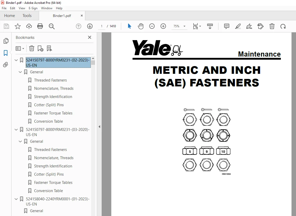
524150797-8000YRM0231-(02-2023)-US-EN 1
General 7
Threaded Fasteners 7
Nomenclature, Threads 7
Strength Identification 8
Cotter (Split) Pins 9
Fastener Torque Tables 14
Conversion Table 16
524150797-8000YRM0231-(03-2020)-US-EN 23
General 27
Threaded Fasteners 27
Nomenclature, Threads 27
Strength Identification 28
Cotter (Split) Pins 29
Fastener Torque Tables 34
Conversion Table 36
524158040-2240YRM0001-(01-2023)-US-EN 43
General 49
Battery Type 49
Lead-Acid Batteries 49
Lithium-Ion Batteries 50
Specific Gravity 50
Chemical Reaction in a Cell 50
Electrical Terms 52
Battery Selection 53
Battery Voltage 54
Battery as a Counterweight 54
Battery Ratings 54
Kilowatt-Hours 54
Battery Maintenance 55
Safety Procedures 55
Maintenance Records 55
New Battery 55
Cleaning Battery 56
Adding Water to Battery 58
Hydrometer 58
Battery Temperature 59
Charging Battery 60
Types of Battery Charges 61
Methods of Charging 62
Troubleshooting Charger 63
Knowing When Battery Is Fully Charged 63
Where to Charge Batteries 63
Equipment Needed 63
Battery Connectors 64
Battery Care 64
Troubleshooting 66
524158040-2240YRM0001-(03-2020)-US-EN 71
General 75
Battery Type 75
Lead-Acid Batteries 75
Lithium-Ion Batteries 76
Specific Gravity 76
Chemical Reaction in a Cell 76
Electrical Terms 78
Battery Selection 78
Battery Voltage 79
Battery as a Counterweight 80
Battery Ratings 80
Kilowatt-Hours 80
Battery Maintenance 80
Safety Procedures 80
Maintenance Records 81
New Battery 81
Cleaning Battery 81
Adding Water to Battery 83
Hydrometer 84
Battery Temperature 85
Charging Battery 86
Types of Battery Charges 86
Methods of Charging 88
Troubleshooting Charger 88
Knowing When Battery Is Fully Charged 89
Where to Charge Batteries 89
Equipment Needed 89
Battery Connectors 90
Battery Care 90
Troubleshooting 92
524164473-4000YRM0481-(08-2016)-US-EN 97
General 101
Description 101
Lowering Control Valve 102
Main Cylinder Repair 103
Disassemble 104
Assemble 105
Free-Lift Cylinder Repair 106
Disassemble 106
Assemble 106
Troubleshooting 108
524223769-2200YRM1128-(01-2023)-US-EN 111
Series Code / Model Designation Reference Table 119
General 121
Deutsch Crimping Tool 122
How to Strip a Wire for Use With Deutsch Crimping Tool 122
How to Crimp With the Deutsch Crimping Tool 123
Calibration Test for the Deutsch Crimping Tool 125
Deutsch Connectors 127
DT, DTM, and DTP Series Connectors 127
HD Series Connectors 170
Metri-Pack Connectors 192
Remove and Install 192
Micro-Pack Connectors 195
Weather-Pack Connectors 196
AMPSEAL Crimping Tools 198
AMP Hand Crimping Tool With Certi-Crimp 198
Description 198
Stripping Wire for Use with AMP Hand Crimping Tool 199
Insulation Crimp Adjustment 200
Maintenance and Inspection for AMP Hand Crimping Tool 200
AMP Hand Crimping Tool 200
Crimp Height Inspection 200
How to use AMP Hand Crimping Tool 201
AMP Pro-Crimper II Tool 201
Description 201
Remove and Install Die Set and Locator Assembly 202
Stripping Wire for Use With AMP PRO-CRIMPER II Tool 202
Contact Support Adjustment 203
Crimp Height Adjustment 204
Maintenance and Inspection Procedures 204
PRO-CRIMPER II Tool 204
Crimp Height Inspection 204
How to Use AMP PRO-CRIMPER II Tool 205
AMPSEAL Connector Assemblies 206
Description for Plug Connector Assembly 206
Seal Plug 207
Contact Crimping 207
Description for Plug Connector and Header Assembly 212
Voltage Reading 215
Seal Plug 215
Contact Crimping 215
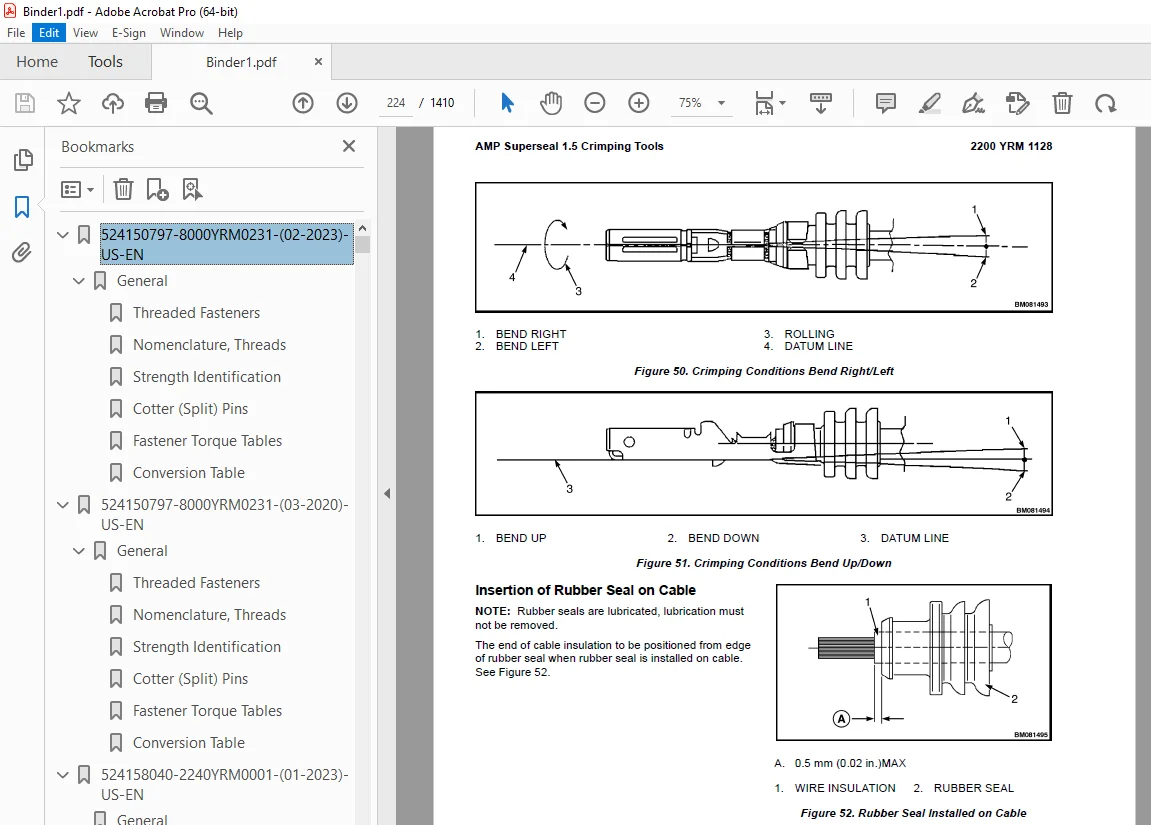
AMP Superseal 1 5 Crimping Tools 222
Mini Mic Receptacle and Tab Contacts 222
Description 222
Crimping Conditions and Measurements 222
Insertion of Rubber Seal on Cable 224
AMP Hand Application Tool 229
Description 229
Maintenance and Inspection 229
Crimp Height Inspection 229
Crimp Height Adjustment 230
How to Use AMP Hand Application Tool 230
AMP Pro-Crimper II Tool 231
Description 231
Remove and Install Die Set and Locator Assembly 231
Adjustments 232
Contact Support 232
Crimp Height 233
Inspections and Maintenance 234
Crimp Height Inspection 234
Visual Inspection 234
Maintenance 235
How to Use Pro-Crimper II Tool 235
AMP Superseal 1 5 Connector Assemblies 236
Description 236
Repair and Maintenance 243
Panel Mount Option 243
AMP Fastin-Faston Hand Tools 244
Description – AMP Double Action Hand Tool 244
Maintenance and Inspection Procedures 244
Daily Maintenance 244
Periodic Tool Inspection 245
Lubrication 245
Visual Inspection 245
Crimp Height Inspection 245
Certi-Crimp Ratchet Inspection 246
How to Use AMP Double Action Hand Tool 247
Description – AMP Extraction Tool 248
Maintenance and Inspection 249
How to Use AMP Extraction Tool 249
AMP Fastin-Faston Receptacles and Housings 251
Description 251
Wire Repair 259
Wire Splicing Requirements 259
Deutsch Jiffy Splice 260
Twisted/Shielded Cable and Leads Repair 266
Special Tools 268
524223769-2200YRM1128-(07-2020)-US-EN 277
Series Code / Model Designation Reference Table 283
General 286
Deutsch Crimping Tool 286
How to Strip a Wire for Use With Deutsch Crimping Tool 286
How to Crimp With the Deutsch Crimping Tool 287
Calibration Test for the Deutsch Crimping Tool 289
Deutsch Connectors 291
DT, DTM, and DTP Series Connectors 291
HD Series Connectors 333
Metri-Pack Connectors 356
Remove and Install 356
Micro-Pack Connectors 358
Weather-Pack Connectors 359
AMPSEAL Crimping Tools 361
AMP Hand Crimping Tool With Certi-Crimp 361
Description 361
Stripping Wire for Use with AMP Hand Crimping Tool 361
Insulation Crimp Adjustment 362
Maintenance and Inspection for AMP Hand Crimping Tool 362
AMP Hand Crimping Tool 362
Crimp Height Inspection 362
How to use AMP Hand Crimping Tool 363
AMP Pro-Crimper II Tool 363
Description 363
Remove and Install Die Set and Locator Assembly 364
Stripping Wire for Use With AMP PRO-CRIMPER II Tool 365
Contact Support Adjustment 365
Crimp Height Adjustment 366
Maintenance and Inspection Procedures 366
PRO-CRIMPER II Tool 366
Crimp Height Inspection 366
How to Use AMP PRO-CRIMPER II Tool 367
AMPSEAL Connector Assemblies 368
Description for Plug Connector Assembly 368
Seal Plug 369
Contact Crimping 369
Description for Plug Connector and Header Assembly 374
Voltage Reading 376
Seal Plug 376
Contact Crimping 376
AMP Superseal 1 5 Crimping Tools 383
Mini Mic Receptacle and Tab Contacts 383
Description 383
Crimping Conditions and Measurements 383
Insertion of Rubber Seal on Cable 385
AMP Hand Application Tool 390
Description 390
Maintenance and Inspection 390
Crimp Height Inspection 390
Crimp Height Adjustment 391
How to Use AMP Hand Application Tool 391
AMP Pro-Crimper II Tool 392
Description 392
Remove and Install Die Set and Locator Assembly 393
Adjustments 393
Contact Support 393
Crimp Height 394
Inspections and Maintenance 395
Crimp Height Inspection 395
Visual Inspection 395
Maintenance 396
How to Use Pro-Crimper II Tool 396
AMP Superseal 1 5 Connector Assemblies 397
Description 397
Repair and Maintenance 404
Panel Mount Option 404
AMP Fastin-Faston Hand Tools 405
Description – AMP Double Action Hand Tool 405
Maintenance and Inspection Procedures 405
Daily Maintenance 405
Periodic Tool Inspection 406
Lubrication 406
Visual Inspection 406
Crimp Height Inspection 406
Certi-Crimp Ratchet Inspection 407
How to Use AMP Double Action Hand Tool 408
Description – AMP Extraction Tool 409
Maintenance and Inspection 409
How to Use AMP Extraction Tool 410
AMP Fastin-Faston Receptacles and Housings 411
Description 411
Wire Repair 418
Wire Splicing Requirements 418
Deutsch Jiffy Splice 419
Twisted/Shielded Cable and Leads Repair 424
Special Tools 427
524233335-1800YRM1188-(01-2016)-US-EN 435
Introduction 439
General 439
Discharging the Capacitors 439
Electric Brake 440
Air Gap 441
Remove 442
Install 443
Troubleshooting 444
524233341-4000YRM1194-(01-2016)-US-EN 449
General 453
Safety Procedures When Working Near Mast 454
Mast Weldments 456
Reach Carriage Assembly 456
Three-Stage Mast 458
Description 458
Operation 459
524233342-4000YRM1195-(07-2019)-US-EN 463
General 467
Safety Procedures When Working Near Mast 467
Load Backrest 468
Remove 468
Install 468
Forks 468
Remove 469
Install 469
Checks, Lift Truck Models NR045EA, NDR035EA (C861); NR035EA, NR040EA, NDR030EA (D815); NR035DA, NR040DA, NDR030DA (A295) 469
Checks, Lift Truck Models NR045EB, NDR035EB (D861); NR035EB, NR040EB, NDR030EB (E815); NR035DB, NR040DB, NDR030DB (B295) 470
Sheaves 472
Hydraulic System 475
Hydraulic Oil 477
Drain 477
Cylinder Identification 479
Fill 480
Main Lift Cylinders 481
Free-Lift Cylinders 481
Reach Carriage Assembly 482
Remove 482
Install 484
Load Rollers 485
Mast 485
Reach Assembly 487
Load Rollers 487
Side Rollers 487
Mast 488
Remove 488
Disassemble 489
Clean and Inspect 490
Assemble 491
Install 493
Lift Cylinders 494
Main Lift Cylinders 494
Remove 494
Install 497
Free-Lift Cylinder 498
Remove 498
Install 499
Lift Chains 500
Clean and Inspect 500
Mast Adjustments 501
General 501
Mast Back Angle Adjustment 501
Load Rollers Adjustment 502
Reach Carriage Assembly 502
Adjust Wear Plugs – Mast 503
Adjust Main-Lift Chains 505
Adjust Free-Lift Chain 505
Adjust Wear Strips 507
Mast Racking 508
Proximity Switches 509
Replace 510
Free-Lift Proximity Switch 510
Load Lowering Proximity Switch (Optional) 511
Adjust 511
Mast Operation Check 511
Lift System Leak Check 512
Lift Cylinder Leak Check 512
Tilt Cylinder Leak Check 512
524233343-4500YRM1196-(01-2016)-US-EN 515
General 519
Safety Procedures When Working Near Mast 519
Description 520
Repair – General 522
Load Backrest 522
Remove 522
Install 522
Forks 523
Replacement 523
Remove 523
Install 523
Reach Carriage Assembly 524
Remove 524
Inspect 525
Install 526
Reach Carriage Assembly Repair 526
Load Rollers Repair 527
Side Rollers Repair (6 9 Mast Only) (NDR030DA and NR035/040DA) 528
Reach Assembly Front Frame 529
Remove 529
Disassemble (With Sideshift) 530
Disassemble (Without Sideshift) 532
Clean and Inspect 533
Assemble (With Sideshift) 533
Assemble (Without Sideshift) 533
Install 534
Single-Reach Scissor Arms 534
Remove and Disassemble 534
Clean and Inspect 538
Assemble and Install 538
Double-Reach Scissor Arms 540
Disassemble 540
Clean and Inspect 544
Assemble 544
Rear Frame Assembly 547
Remove 547
Disassemble 549
Clean and Inspect 550
Assemble 550
Install 550
Reach Cylinders 552
Remove 552
Disassemble 553
Clean and Inspect 554
Assemble 554
Install 555
Tilt Cylinder 555
Remove 555
Clean, Inspect, and Repair 556
Install 557
Sideshift Cylinder 557
Repair 557
Front Selector Valve 558
Rear Selector Valve 559
Reach Assembly Adjustments 559
Check Adjustment 560
Adjust Side Rollers and Load Rollers 561
Adjust Reach Cylinders 562
Lift Chains 563
Inspect 563
Clean and Lubricate 564
Adjust Main-Lift Chains 564
Adjust Free-Lift Chains 564
Specifications 565
Troubleshooting 568
550072990-8000YRM1619-(09-2019)-US-EN 573
Schematics 577
550072991-8000YRM1617-(02-2018)-US-EN 607
General 611
Removing Covers 612
Front Frame Panel (Left and Right) 612
Operator Compartment Cover 612
Drive Unit Compartment Door 613
Caster Wheel Cover 613
Discharging the Capacitors 613
How to Move Disabled Truck 614
How to Tow Lift Truck 614
How to Put Lift Truck on Blocks 615
How to Raise Load Wheels 615
How to Raise the Drive Tire End 615
How to Raise the Entire Lift Truck 616
Manual Lowering Valve 617
NDR030/035EB and NR030/040/045EB 617
NDR030DB and NR035/040DB 617
Transporting 618
Loading 618
Unloading 619
Preparation for Use 619
Preparation After Shipment 619
Preparation After Storage 619
Safety Procedures When Working Near Mast 619
Maintenance Schedule 621
Maintenance Procedures Every 8 Hours or Daily 627
Checks With Key Switch Turned OFF 628
Battery 628
Tires and Wheels 629
Frame and Load Wheels 629
Safety Labels 629
Overhead Guard 629
Forks Check 630
Lift Chain Check 631
Mast Check 632
Reach, Tilt, and Sideshift 632
Checks With Key Switch Turned ON 632
Operation 632
Hydraulic System 633
Dash Display 633
Lift System Operation 634
Multifunction Control Handle 635
Brake 636
Steering System 636
Maintenance Procedures Every500 Hours or 3 Months 636
Master Drive Unit 636
Hydraulic System 636
Hydraulic Filter Element Change 638
Caster Adjustment 638
Elastomer Spring Adjustment 639
Spring Pack Replacement 640
Remove Spring Assembly 640
Replace Spring Pack 640
Install Spring Assembly 641
Drive Tire Check 641
Lift System Operation 642
Forks Check 642
Mast 642
Lift Chains 643
Other Lubrication 644
Maintenance Procedures Every 2000 Hours or Yearly 644
Brakes 644
Check 644
Electric System 644
Main Contactor 644
Inspect 644
Forks, Check 645
Hydraulic System 645
Drain 645
Cylinder Identification 647
Fill 648
Main Lift Cylinders 649
Free-Lift Cylinders 649
Hydraulic Filter Change 650
Check Hydraulic Strainer 651
Lift and Tilt System Leaks Check 651
Lift System 651
Tilt System 652
Battery Maintenance 652
How to Charge Battery 652
How to Change Battery 654
Tires and Wheels 656
Drive Tire 656
How to Change Drive Tire 657
Tandem Load Wheels 658
Caster Wheels 658
Remove 658
Install 659
Preparation for Storage 660
Short-Term Storage (1 to 6 months) 660
Long-Term Storage (6 months or longer) 660
550073166-0620YRM1621-(12-2018)-US-EN 663
General 667
Special Precautions 667
Discharging the Capacitors 667
Traction Motor Repair 667
Remove 668
Disassemble 670
Clean/Inspect 674
Assemble 675
Install 676
Hydraulic Motor Repair 677
Disassemble 677
Inspect 679
Assemble 680
Special Tools 681
Tool Chart 681
Troubleshooting 682
550073167-0630YRM1609-(03-2021)-US-EN 687
Master Drive Unit 691
General 691
Description 691
Maintenance 692
Changing the Oil 692
Remove 692
Clean and Inspect 697
Install 700
Troubleshooting 701
550073168-1600YRM1610-(04-2014)-US-EN 705
550073169-0100YRM1615-(01-2016)-US-EN 753
General 757
Description 758
Repairs – General 758
Covers, Panels, and Plates 758
Front Frame Panel (Left and Right) 758
Operator Compartment Cover 759
Drive Unit Compartment Door 759
Door Pad 759
Operator Back Pad 760
Side-Stance Models 760
Forward-Stance Models 760
Operator Front Pad 760
Caster Wheel Cover 760
Load Wheels 761
Remove 761
Install 762
Overhead Guard Replacement 763
Remove 768
Install 768
Front Lights 768
Bulb Replacement 768
Assembly Replacement 769
Rear Work and Caution Light 770
Caution Light 770
Painting Instructions 770
Safety Labels Replacement 772
550073170-1900YRM1616-(12-2018)-US-EN 779
General 783
Discharging the Capacitors 784
Description 784
Control Handle 785
Sidestance Control Handle 785
Fore/Aft Stance 786
Maintenance 786
Oil Level and Leaks 787
Operation 787
Oil Change 787
Drain 787
Cylinder Identification 789
Fill 790
Main Lift Cylinders 791
Free-Lift Cylinders 791
Breather Cap 792
Inspect 792
Oil Filter 793
Change 793
Oil Strainer 793
Check 793
Hydraulic System 793
General 794
Cleaning 794
Noise Levels 794
Hoses 794
Fittings 796
Lift Pump and Motor 796
Complete Unit 797
Remove 797
Install 798
Lift Pump 799
Components 800
Pressure Flange Fitting 800
Supply and Return Fittings 801
Manual Lowering Valve 801
Pressure Test Ports 801
Pressure Transducer 802
Relief Valve 804
Lowering Control Valve 804
Remove Pump 804
Install Pump 805
Auxiliary Hydraulics 805
Auxiliary Pump and Motor 806
Remove 806
Disassemble 807
Assemble 807
Install 808
Front Selector Valve 809
Rear Selector Valve 809
Hydraulic Tank 810
Remove 811
Disassemble 812
Breather Assembly 812
Filter Assembly 813
Tank Fittings 814
Clean and Inspect 814
Assemble 814
Breather Assembly 814
Filter Assembly 815
Tank Fittings 815
Install 816
Specifications 816
Troubleshooting 816
550073171-9000YRM1622-(01-2022)-US-EN 821
SECTION 9030 Electrical System 827
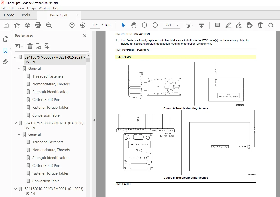
Group 03 – General Maintenance and Diagnostic Data 831
Group 20 – Diagnostic Trouble Codes 845
550073171-9000YRM1622-(10-2019)-US-EN 1019
SECTION 9030 Electrical System 1025
Group 03 – General Maintenance and Diagnostic Data 1029
Group 20 – Diagnostic Trouble Codes 1041
550073172-2200YRM1612-(07-2018)-US-EN 1215
General 1221
Discharging the Internal Capacitors 1222
Static Strap 1222
Inspect 1223
Replace 1223
Battery Connection 1223
Inspect 1223
Replacing Cables 1223
Key Switch 1224
Replace 1225
Major Electrical System Features 1226
Integrated System 1227
CANbus Advantages 1227
CANbus Communications 1227
Electric Steering / Steer Caster (Optional) 1227
Centering Proximity Sensor 1227
Traction 1228
CAN I/O 1228
Input Devices 1228
Output Devices 1228
Encoder Integrity 1228
Test Encoders 1228
Proximity Switches 1228
Key Switch 1229
Multifunction Displays 1229
BDI 1229
Speed 1229
Steer Angle 1229
Truck Hours 1229
Operational Mode 1230
Setup 1230
Setup Instructions 1230
ACE2 / ACE3 Traction and Hydraulic Controllers 1230
Normal Operation 1230
Display 1230
Password Access 1230
Startup Checklist 1230
Truck Operation Mode 1231
Diagnostics 1231
Calibrations 1231
AC Motor Controllers 1232
Controller Removal 1233
Install 1233
Low-Voltage Protection Function 1233
CDF File Installation Procedure 1234
Contactor and Electrical Panel Checks 1234
Fuses 1235
Contactors 1235
General 1235
Test 1236
Tips 1236
Disassemble and Assemble 1237
Instrument Panel Removal and Installation 1238
Key Switch Removal and Installation 1238
Remove 1238
Install 1238
Integrated Fuse Board (IFB) 1238
Replace 1239
Diodes 1240
Power Disconnect Switch 1241
Replace 1241
Side-Stance Controls 1243
Multifunction Control Handle 1243
Horn 1244
Inspection 1244
Remove 1245
Install 1247
Forward-Stance Controls 1247
Control Handle Functions 1247
Repair 1248
Aft Travel Control Handle Option 1249
Repair 1250
Aft Handle Sensor Adjustment 1251
Control Handle Disassembly and Repair 1251
Thumb Grip Pad Replacement 1252
Handle Grip and Switch Repairs 1253
Handle Grip Support Mounting 1253
Handle Disassembly 1254
Steering Handle 1256
Steering Unit Repair 1256
Foot Switches 1259
Brake Switch 1260
Operator Sensing 1260
Repair 1260
Freezer Floor Plate Repair 1261
General 1261
Heater Harness 1263
Dash Display Assembly 1263
Description 1263
Remove 1264
Test 1265
Install 1265
Horn 1265
Audible Alarm 1266
Light Assemblies 1267
Front Lights 1267
Bulb Replacement 1267
Assembly Replacement 1267
Rear Work and Caution Light 1268
Rear Work Light 1268
Caution Light 1268
Light Switches 1269
Cooling Fans 1270
Electrical Compartment Fans 1270
Replace 1272
Operator Fan 1272
Repair 1272
Impact Sensor 1275
Remove 1275
Install 1276
Height Proximity Switch 1276
Test 1277
Remove 1277
Install 1277
Adjust 1278
Load Transport Proximity Switch 1279
Fork Height Sensor Option 1280
Remove 1280
Encoder Assembly 1280
Timing Belt 1281
Install 1282
Encoder Assembly 1282
Timing Belt 1283
Reach Position Sensor 1283
Remove 1283
Install 1286
Retract Sensor 1286
Remove 1287
Install 1288
Tilt Leveling 1289
Remove 1289
Install 1290
Laser Option 1290
Remove 1291
Adjustment 1291
Horizontal Adjustment 1291
Vertical Adjustment 1293
Install 1293
Camera Option 1293
Description 1293
Remove 1296
Install 1296
550073173-2200YRM1613-(02-2014)-US-EN 1299
550073174-2200YRM1614-(01-2019)-US-EN 1323
General 1333
Introduction 1333
Description 1333
Button Keypad 1333
LED Indicator Lights 1333
LCD Screen 1333
Dash Display Menu Access 1334
Menu Navigation 1334
Dash Display Menu Operation 1334
Nodes 1334
Menu Structure 1334
Service-Level Menu 1335
Hour Meters 1335
H1 Truck Hours 1337
H2 Traction Hours 1337
H3 Pump Hours 1337
H4 Steer Hours 1337
H5 Odometer Hours 1337
H10 Display Hours 1337
H30 Traction Node Hours 1337
H40 Steer Node Hours 1337
H41 Steer Caster Node Hours 1337
H50 Pump Node Hours 1337
H90 CAN I/O Hours 1337
Performance 1338
Performance Level 1 1338
P1 1 Forward 1339
P1 2 Reverse 1339
P1 3 Acceleration 1339
P1 4 Plug 1340
P1 5 Coast 1340
P1 6 Lift Speed 1340
P1 7 Lower Speed 1340
P1 8 Lift Accel 1340
P1 9 Lift Decel 1340
P1 10 Lower Accel 1340
P1 11 Lower Decel 1340
P1 16 Sideshift Speed 1340
P1 19 Aft FW Spd 1340
P1 20 Aft Rev Spd 1340
P1 21 Aft Decel 1341
P1 22 Aft Plug 1341
P1 32 Steer Effort 1341
P1 33 Steer Ratio 1341
P1 34 Ext Speed 1341
P1 36 Ret Speed 1341
P1 38 Tilt Up Speed 1341
P1 39 Tilt Down Speed 1341
Passwords 1342
Add Password 1342
Delete Password 1342
Edit Password 1342
Operator Password 1343
Clear Log 1343
Operator Logs 1343
Operator 1-150 1343
Information 1344
I1 Series 1344
I3 Serial Number 1344
I5 Truck Voltage 1344
Settings 1345
S1 Metric 1348
S2 User Performance 1348
S3 Timeout 1348
S4 Battery Type 1348
S5 BDI Startup Full 1348
S6 BDI Full 1348
S7 BDI Empty 1348
S8 BDI Reset 1348
S9 Lift Interrupt 1349
S10 Audible Warning 1349
S11 Visual Warning 1349
S12 Checklist 1349
S13 Maint Reminder 1349
S14 Restore Default 1350
S15 Truck Lockout 1350
S18 Lift Lim Overrid 1350
S42 Steer Mode 1350
S43 Simultaneity 1350
S44 Carry Position 1350
S45 Load Weight Mon 1350
S46 Fork Laser Line 1350
S47 Aft Handle 1350
S48 Camera 1350
S49 Trac Slow Extend 1350
S50 Auto Tilt 1350
S51 Free Lft Spd Red 1350
S52 Shelf Height Sel 1350
S53 Load Wt Spd Red 1351
S54 Free Lift Height 1351
S55 Impact Action 1351
S56 Impact Sound Len 1351
S57 Hard Duration 1351
S58 Hard Accel 1351
S59 Soft Duration 1351
S60 Soft Accel 1351
Software Version 1351
Error Log 1351
(E1) Error Log 1 1352
Error 1 1 (E1 1) 1352
Error 1 2 (E1 2) 1352
Error 1 3 (E1 3) 1352
Error 1 4 (E1 4) 1352
Impact Log 1353
Impact Log 1 (T1) 1353
Diagnostics 1353
Diagnostics 1353
D1 Status 1354
D2 Input 1354
D3 Output 1354
D1 Status 1354
D1 1 CAN 1355
D1 2 Contactor 1355
D1 3 Full Traction 1355
D1 4 Limp Traction 1355
D1 5 Steering 1355
D1 6 Lift 1355
D1 7 Lower 1355
D1 8 Tilt 1355
D1 9 Side Shift 1355
D1 10 EXT/RET 1355
D2 Inputs 1356
D2 10 Display 1357
D2 10 1 Bus Error 1358
D2 10 2 Bus Max Error 1358
D2 10 30 Traction 1358
D2 10 40 Steer 1358
D2 10 41 Steer Cast 1358
D2 10 50 Pump 1358
D2 10 51 Aux Pump 1358
D2 10 60 CTRL Hand 1358
D2 10 80 Impact Module 1358
D2 10 90 CAN I/O 1358
D2 10 91 Remote Module 1358
D2 30 Traction 1358
D2 30 1 Target Speed 1360
D2 30 2 Motor Speed 1360
D2 30 3 Motor ENC 1360
D2 30 5 Cont Temp 1360
D2 30 6 Motor Temp 1360
D2 30 7 Motor Curr 1360
D2 30 8 Cap V 1360
D2 30 9 Cap Max V 1360
D2 30 10 Cap Min V 1361
D2 30 11 Key V 1361
D2 30 12 Key Max V 1361
D2 30 13 Key Min V 1361
D2 30 14 Brake Connect 1361
D2 30 16 MC Connect 1361
D2 30 19 Brake SW 1361
D2 30 20 OP Sen SW 1361
D2 30 27 Load Hold Current 1361
D2 30 28 Lift/Lower Valve Current 1361
D2 30 31 Bank Out Current 1361
D2 30 32 SOC 1361
D2 40 Steer 1361
D2 40 1 Target Speed 1363
D2 40 2 Motor Speed 1363
D2 40 3 Motor ENC 1363
D2 40 5 Cont Temp 1363
D2 40 7 Motor Curr 1363
D2 40 8 Cap V 1363
D2 40 9 Cap Max V 1363
D2 40 10 Cap Min V 1363
D2 40 11 Key V 1363
D2 40 12 Key Max V 1363
D2 40 13 Key Min V 1363
D2 40 17 Center Prox SW 1363
D2 40 19 Steer Angle 1364
D2 41 Steer Caster 1364
D2 41 1 Target Speed 1365
D2 41 2 Motor Speed 1365
D2 41 3 Motor ENC 1365
D2 41 5 Cont Temp 1365
D2 41 6 Motor Temp 1365
D2 41 7 Motor Curr 1365
D2 41 8 Cap V 1366
D2 41 9 Cap Max V 1366
D2 41 10 Cap Min V 1366
D2 41 11 Key V 1366
D2 41 12 Key Max V 1366
D2 41 13 Key Min V 1366
D2 41 14 Center Prox SW 1366
D2 41 16 Steer Angle 1366
D2 50 Pump 1366
D2 50 1 Target Speed 1367
D2 50 2 Motor Speed 1367
D2 50 3 Motor ENC 1368
D2 50 5 Cont Temp 1368
D2 50 6 Motor Temp 1368
D2 50 7 Motor Curr 1368
D2 50 8 Cap V 1368
D2 50 9 Cap Max V 1368
D2 50 10 Cap Min V 1368
D2 50 11 Key V 1368
D2 50 12 Key Max V 1368
D2 50 13 Key Min V 1368
D2 50 14 Mast Prox SW 1368
D2 51 Aux Pump 1368
D2 51 1 Target Speed 1369
D2 51 2 Motor Speed 1369
D2 51 6 Motor Temp 1369
D2 51 7 Motor Curr 1369
D2 51 14 Motor Lock 1369
D2 51 15 Motor Lock 1 1369
D2 60 Control Handle 1369
D2 60 1 Horn SW 1370
D2 60 10 Tilt Up SW 1370
D2 60 11 Tilt Down SW 1370
D2 60 12 Shift Right SW 1370
D2 60 13 Shift Left SW 1371
D2 50 18 Function SW 1371
D2 60 19 Trac Input 1371
D2 60 20 Lift/Lower Input 1371
D2 60 21 SS/ER Input 1371
D2 60 22 ER Input 1371
D2 60 23 Tilt Input 1371
D2 80 Impact Sensor 1371
D2 80 1 Soft Impact 1371
D2 80 10 Hard Impact 1371
D2 90 CAN I/O 1372
D2 90 1 Height ENC 1374
D2 90 2 Height ENC 1374
D2 90 4 Ret Pos Prox Sen 1374
D2 90 11 Key V 1374
D2 90 12 Key Max V 1374
D2 90 13 Key Min V 1374
D2 90 23 Steer Stat 1374
D2 90 24 Cast Steer Stat 1374
D2 90 25 Pressure Sen 1374
D2 90 26 Horn Connect 1374
D2 90 28 Cont Fan Connect 1374
D2 90 30 Comp Fan Connect 1374
D2 90 32 TFD Coil Connect 1375
D2 90 34 ER Coil Connect 1375
D2 90 36 SS Coil Connect 1375
D2 90 38 Aux Rev Connect 1375
D2 90 40 Aux FWD Connect 1375
D2 90 42 Lower Connect 1375
D2 90 44 Backup Connect 1375
D2 90 46 Tilt Connect 1375
D2 90 52 Hld/Lft Connect 1375
D2 90 54 Strobe Connect 1375
D2 91 Remote Module 1375
D2 91 1 Height Prox Sen 1376
D2 91 2 Ret Pos Sen 1376
D2 91 3 Tilt Sen 1376
D2 91 4 Tilt Connect 1376
D2 91 5 SS Connect 1376
D2 91 6 ER Connect 1376
D2 91 7 Aux FWD Connect 1376
D2 91 8 Aux Rev Connect 1377
D3 Output 1377
D3 10 Display 1377
D3 10 10 Display Com 1378
D3 10 30 Trac Comm 1378
D3 10 40 Steer Com 1378
D3 10 41 Caster Steer Com 1378
D3 10 50 Pump Com 1378
D3 10 51 Aux Pump Com 1378
D3 10 60 Cont Handle Com 1378
D3 10 80 Impact Sensor 1378
D3 10 90 CAN I/O Com 1378
D3 10 91 Remote Module 1378
D3 30 Traction 1378
D3 30 1 U-V Line DC Curr 1379
D3 30 2 U-W Line DC Curr 1379
D3 30 3 V-W Line DC Curr 1379
D3 30 4 Motor Open 1379
D3 30 5 Motor Circuit 1379
D3 30 6 Brake 1379
D3 30 7 MC 1379
D3 40 Steer 1379
D3 40 1 U-V Line DC Curr 1380
D3 40 2 U-W Line DC Curr 1380
D3 40 3 V-W Line DC Curr 1380
D3 40 4 Motor Open 1380
D3 40 5 Motor Circuit 1380
D3 40 6 Status Line 1380
D3 41 Steer Caster 1380
D3 41 1 U-V Line DC Curr 1381
D3 41 2 U-W Line DC Curr 1381
D3 41 3 V-W Line DC Curr 1381
D3 41 6 Status Line 1381
D3 50 Pump 1381
D3 50 1 U-V Line DC Curr 1382
D3 50 2 U-W Line DC Curr 1382
D3 50 3 V-W Line DC Curr 1382
D3 50 4 Motor Open 1382
D3 50 5 Motor Circuit 1382
D3 90 CAN I/O 1382
D3 90 1 ER Coil 1384
D3 90 2 SS Coil 1384
D3 90 3 Aux Rev 1384
D3 90 4 Aux FWD 1384
D3 90 5 TFD Coil 1384
D3 90 6 Strobe 1384
D3 90 7 Comp Fan 1384
D3 90 8 Cont Fan 1384
D3 90 9 Lower Coil 1384
D3 90 10 Backup Alarm 1384
D3 90 11 Tilt Coil 1384
D3 90 12 Load Hold 1384
D3 90 13 Lift 1384
D3 90 14 Horn 1384
D3 91 Remote 1385
D3 91 1 ER Coil 1385
D3 91 2 SS Coil 1385
D3 91 3 Aux Rev 1385
D3 91 4 Aux FWD 1385
D3 91 5 Tilt Coil 1385
D3 91 6 Camera 1385
D3 91 7 Laser 1386
Calibration 1386
550073175-8000YRM1618-(01-2016)-US-EN 1393
Lubrication Specifications 1397
Oil Capacities 1397
Hydraulic System 1397
Lift Specifications 1398
Tire Sizes 1402
Torque Specifications 1403
Master Drive Unit 1403
Reach Carriage 1403
Mast 1403
Hydraulic System (NDR030/035EB and NR030/040/045EB) 1404
Hydraulic System (NDR030DB and NR035/040DB) 1404
Steering System 1404
Load Wheels (Lift trucks built before October 2015) 1404
Load Wheels (Lift trucks built after October 2015) 1404
Fuses 1405
Coil Resistance Values 1405
Battery Specifications 1407
S.V 05/24