Yale Forklift E861 (NR035EC, NR040EC, NR045EC, NDR30EC, NDR35EC) Service Manual PDF
$36.95
Yale Forklift E861 (NR035EC, NR040EC, NR045EC, NDR30EC, NDR35EC) Service Manual – PDF DOWNLOAD
Description
Yale Forklift E861 (NR035EC, NR040EC, NR045EC, NDR30EC, NDR35EC) Service Manual – PDF DOWNLOAD
FILE DETAILS:
Yale Forklift E861 (NR035EC, NR040EC, NR045EC, NDR30EC, NDR35EC) Service Manual – PDF DOWNLOAD
Language : English
Pages : 1592
Downloadable : Yes
File Type : PDF
IMAGES PREVIEW OF THE MANUAL:
TABLE OF CONTENTS:
Yale Forklift E861 (NR035EC, NR040EC, NR045EC, NDR30EC, NDR35EC) Service Manual – PDF DOWNLOAD
524150797-8000YRM0231-(02-2023)-US-EN 1
General 7
Threaded Fasteners 7
Nomenclature, Threads 7
Strength Identification 8
Cotter (Split) Pins 9
Fastener Torque Tables 14
Conversion Table 16
524150797-8000YRM0231-(03-2020)-US-EN 23
General 27
Threaded Fasteners 27
Nomenclature, Threads 27
Strength Identification 28
Cotter (Split) Pins 29
Fastener Torque Tables 34
Conversion Table 36
524158040-2240YRM0001-(01-2023)-US-EN 43
General 49
Battery Type 49
Lead-Acid Batteries 49
Lithium-Ion Batteries 50
Specific Gravity 50
Chemical Reaction in a Cell 50
Electrical Terms 52
Battery Selection 53
Battery Voltage 54
Battery as a Counterweight 54
Battery Ratings 54
Kilowatt-Hours 54
Battery Maintenance 55
Safety Procedures 55
Maintenance Records 55
New Battery 55
Cleaning Battery 56
Adding Water to Battery 58
Hydrometer 58
Battery Temperature 59
Charging Battery 60
Types of Battery Charges 61
Methods of Charging 62
Troubleshooting Charger 63
Knowing When Battery Is Fully Charged 63
Where to Charge Batteries 63
Equipment Needed 63
Battery Connectors 64
Battery Care 64
Troubleshooting 66
524158040-2240YRM0001-(03-2020)-US-EN 71
General 75
Battery Type 75
Lead-Acid Batteries 75
Lithium-Ion Batteries 76
Specific Gravity 76
Chemical Reaction in a Cell 76
Electrical Terms 78
Battery Selection 78
Battery Voltage 79
Battery as a Counterweight 80
Battery Ratings 80
Kilowatt-Hours 80
Battery Maintenance 80
Safety Procedures 80
Maintenance Records 81
New Battery 81
Cleaning Battery 81
Adding Water to Battery 83
Hydrometer 84
Battery Temperature 85
Charging Battery 86
Types of Battery Charges 86
Methods of Charging 88
Troubleshooting Charger 88
Knowing When Battery Is Fully Charged 89
Where to Charge Batteries 89
Equipment Needed 89
Battery Connectors 90
Battery Care 90
Troubleshooting 92
524223769-2200YRM1128-(01-2023)-US-EN 97
Series Code / Model Designation Reference Table 105
General 107
Deutsch Crimping Tool 108
How to Strip a Wire for Use With Deutsch Crimping Tool 108
How to Crimp With the Deutsch Crimping Tool 109
Calibration Test for the Deutsch Crimping Tool 111
Deutsch Connectors 113
DT, DTM, and DTP Series Connectors 113
HD Series Connectors 156
Metri-Pack Connectors 178
Remove and Install 178
Micro-Pack Connectors 181
Weather-Pack Connectors 182
AMPSEAL Crimping Tools 184
AMP Hand Crimping Tool With Certi-Crimp 184
Description 184
Stripping Wire for Use with AMP Hand Crimping Tool 185
Insulation Crimp Adjustment 186
Maintenance and Inspection for AMP Hand Crimping Tool 186
AMP Hand Crimping Tool 186
Crimp Height Inspection 186
How to use AMP Hand Crimping Tool 187
AMP Pro-Crimper II Tool 187
Description 187
Remove and Install Die Set and Locator Assembly 188
Stripping Wire for Use With AMP PRO-CRIMPER II Tool 188
Contact Support Adjustment 189
Crimp Height Adjustment 190
Maintenance and Inspection Procedures 190
PRO-CRIMPER II Tool 190
Crimp Height Inspection 190
How to Use AMP PRO-CRIMPER II Tool 191
AMPSEAL Connector Assemblies 192
Description for Plug Connector Assembly 192
Seal Plug 193
Contact Crimping 193
Description for Plug Connector and Header Assembly 198
Voltage Reading 201
Seal Plug 201
Contact Crimping 201
AMP Superseal 1 5 Crimping Tools 208
Mini Mic Receptacle and Tab Contacts 208
Description 208
Crimping Conditions and Measurements 208
Insertion of Rubber Seal on Cable 210
AMP Hand Application Tool 215
Description 215
Maintenance and Inspection 215
Crimp Height Inspection 215
Crimp Height Adjustment 216
How to Use AMP Hand Application Tool 216
AMP Pro-Crimper II Tool 217
Description 217
Remove and Install Die Set and Locator Assembly 217
Adjustments 218
Contact Support 218
Crimp Height 219
Inspections and Maintenance 220
Crimp Height Inspection 220
Visual Inspection 220
Maintenance 221
How to Use Pro-Crimper II Tool 221
AMP Superseal 1 5 Connector Assemblies 222
Description 222
Repair and Maintenance 229
Panel Mount Option 229
AMP Fastin-Faston Hand Tools 230
Description – AMP Double Action Hand Tool 230
Maintenance and Inspection Procedures 230
Daily Maintenance 230
Periodic Tool Inspection 231
Lubrication 231
Visual Inspection 231
Crimp Height Inspection 231
Certi-Crimp Ratchet Inspection 232
How to Use AMP Double Action Hand Tool 233
Description – AMP Extraction Tool 234
Maintenance and Inspection 235
How to Use AMP Extraction Tool 235
AMP Fastin-Faston Receptacles and Housings 237
Description 237
Wire Repair 245
Wire Splicing Requirements 245
Deutsch Jiffy Splice 246
Twisted/Shielded Cable and Leads Repair 252
Special Tools 254
524223769-2200YRM1128-(07-2020)-US-EN 263
Series Code / Model Designation Reference Table 269
General 272
Deutsch Crimping Tool 272
How to Strip a Wire for Use With Deutsch Crimping Tool 272
How to Crimp With the Deutsch Crimping Tool 273
Calibration Test for the Deutsch Crimping Tool 275
Deutsch Connectors 277
DT, DTM, and DTP Series Connectors 277
HD Series Connectors 319
Metri-Pack Connectors 342
Remove and Install 342
Micro-Pack Connectors 344
Weather-Pack Connectors 345
AMPSEAL Crimping Tools 347
AMP Hand Crimping Tool With Certi-Crimp 347
Description 347
Stripping Wire for Use with AMP Hand Crimping Tool 347
Insulation Crimp Adjustment 348
Maintenance and Inspection for AMP Hand Crimping Tool 348
AMP Hand Crimping Tool 348
Crimp Height Inspection 348
How to use AMP Hand Crimping Tool 349
AMP Pro-Crimper II Tool 349
Description 349
Remove and Install Die Set and Locator Assembly 350
Stripping Wire for Use With AMP PRO-CRIMPER II Tool 351
Contact Support Adjustment 351
Crimp Height Adjustment 352
Maintenance and Inspection Procedures 352
PRO-CRIMPER II Tool 352
Crimp Height Inspection 352
How to Use AMP PRO-CRIMPER II Tool 353
AMPSEAL Connector Assemblies 354
Description for Plug Connector Assembly 354
Seal Plug 355
Contact Crimping 355
Description for Plug Connector and Header Assembly 360
Voltage Reading 362
Seal Plug 362
Contact Crimping 362
AMP Superseal 1 5 Crimping Tools 369
Mini Mic Receptacle and Tab Contacts 369
Description 369
Crimping Conditions and Measurements 369
Insertion of Rubber Seal on Cable 371
AMP Hand Application Tool 376
Description 376
Maintenance and Inspection 376
Crimp Height Inspection 376
Crimp Height Adjustment 377
How to Use AMP Hand Application Tool 377
AMP Pro-Crimper II Tool 378
Description 378
Remove and Install Die Set and Locator Assembly 379
Adjustments 379
Contact Support 379
Crimp Height 380
Inspections and Maintenance 381
Crimp Height Inspection 381
Visual Inspection 381
Maintenance 382
How to Use Pro-Crimper II Tool 382
AMP Superseal 1 5 Connector Assemblies 383
Description 383
Repair and Maintenance 390
Panel Mount Option 390
AMP Fastin-Faston Hand Tools 391
Description – AMP Double Action Hand Tool 391
Maintenance and Inspection Procedures 391
Daily Maintenance 391
Periodic Tool Inspection 392
Lubrication 392
Visual Inspection 392
Crimp Height Inspection 392
Certi-Crimp Ratchet Inspection 393
How to Use AMP Double Action Hand Tool 394
Description – AMP Extraction Tool 395
Maintenance and Inspection 395
How to Use AMP Extraction Tool 396
AMP Fastin-Faston Receptacles and Housings 397
Description 397
Wire Repair 404
Wire Splicing Requirements 404
Deutsch Jiffy Splice 405
Twisted/Shielded Cable and Leads Repair 410
Special Tools 413
550191462-0100YRM2082-(08-2019)-US-EN 421
General 425
Discharging the Internal Capacitors 425
Description 428
Repairs – General 429
Covers, Panels, and Plates 429
Service Access Panel 429
Removal 430
Inspection and Cleaning 430
Installation 430
Operator Compartment Covers 431
Front Covers (Left and Right) 431
Main Cover, Battery Tray Cover (With Tiller Cover), and Service Cover 432
Remove 432
Install 436
Caster Cover 436
Compartment Door Assembly 437
Inspection 438
Door Latch and Stop 438
Remove 438
Inspect 439
Install 439
Adjustment 439
Door Pad 439
Remove 440
Install 440
Operator Back Pads 440
Side-Stance Models 440
Forward-Stance Models 440
Operator Wall Pad 441
Storage Container 441
Remove 441
Base Arms and Load Wheel Boxes 441
Description 441
Inspection (Bolt-On Wheel Box) 441
Inspection (Welded Wheel Box) 442
Repair 442
Overhead Guard Replacement 442
Remove 444
Inspect 444
Install 444
Light Assemblies 444
Painting and Vinyl Wrap Instructions 445
Painting Instructions 445
Vinyl Wrap 445
Removal 446
Surface Preparation 446
Installation 447
Repair 448
Safety Labels Replacement 448
Frame Fasteners 450
Repair 450
Threaded Insert Removal 450
Inspection 450
Install 450
550191463-0620YRM2083-(08-2019)-US-EN 453
General 457
Discharging the Internal Capacitors 457
Traction Motor Repair 460
Remove 460
Disassemble 463
Clean/Inspect 468
Assemble 468
Install 469
Hydraulic Motor Repair 470
Lift Truck Models NDR030DC, NR035-040DC (C295) 470
Disassemble 470
Inspect 472
Assemble 472
Lift Truck Models NR035EC, NR040EC, NR045EC, NDR030EC, NDR035EC (E861) 472
25cc (EE Option) and 32cc Hydraulic Pumps 472
Disassemble 472
Inspect 475
Assemble 475
28/9cc Dual Pump 476
Disassemble 476
Inspect 479
Assemble 479
Auxiliary Motor Repair 480
General 480
Special Tools 481
Tool Chart 481
Troubleshooting 481
550191464-0630YRM2084-(01-2021)-US-EN 485
General 489
General 489
Description 489
Discharging The Capacitors 490
Master Drive Unit Repair 494
Maintenance 494
Draining the Oil 494
Remove 494
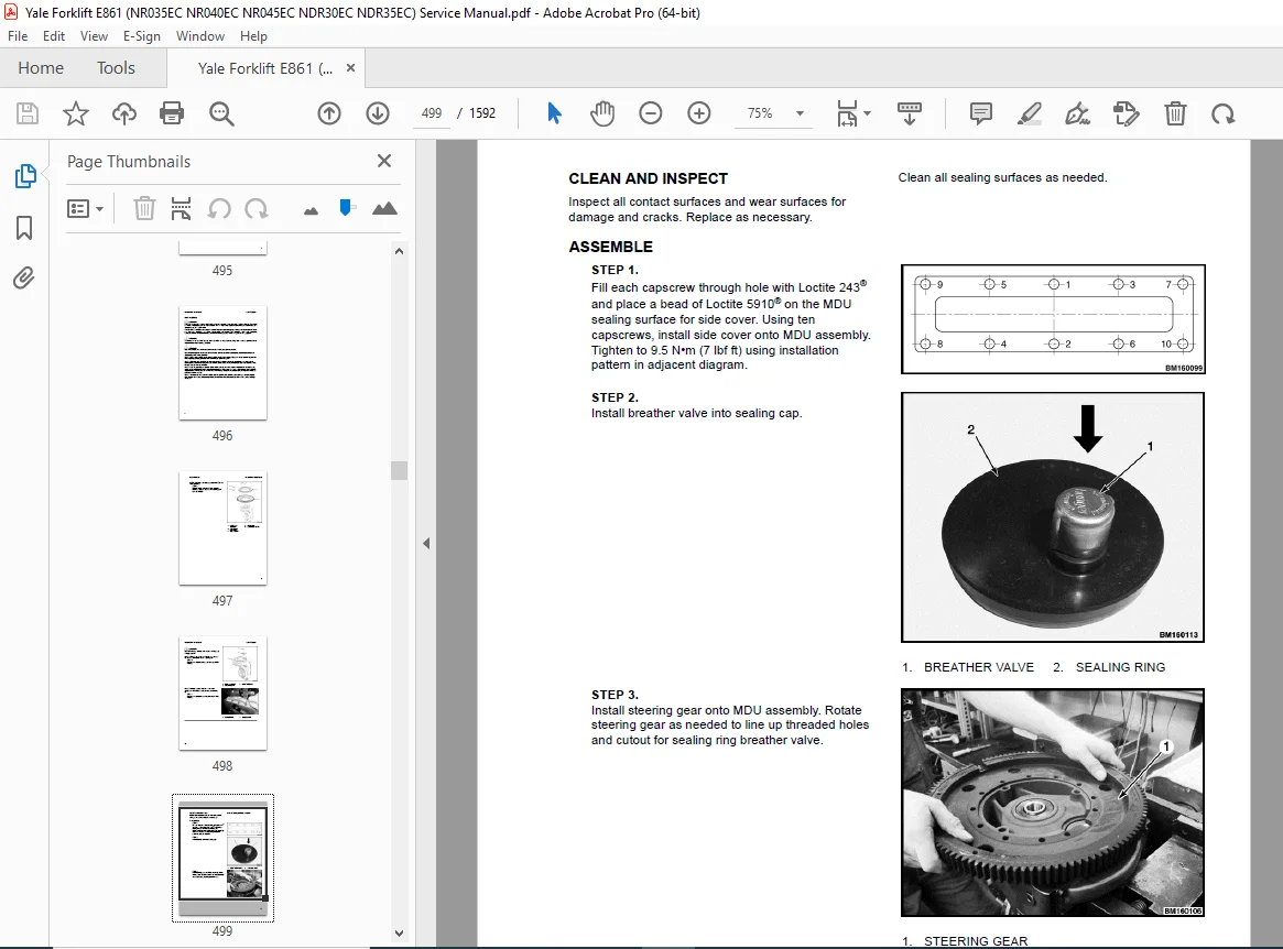
Clean and Inspect 499
Install 501
Replace the Wheel Seal on Kordel Drive Units 501
Tools required 501
Truck setup 501
Wheel shaft seal and protection ring removal (method 1) 501
Wheel shaft seal and protection ring removal (method 2) 502
Wheel shaft seal and protection ring installation 504
Troubleshooting 505
550191464-0630YRM2084-(09-2022)-US-EN 507
General 513
General 513
Description 514
Discharging The Capacitors 515
Master Drive Unit Repair 519
Maintenance 519
Draining the Oil 519
Remove 519
Disassemble 521
Clean and Inspect 522
Assemble 522
Install 523
Replace the Wheel Seal on Kordel Drive Units 524
Tools required 524
Truck setup 524
Wheel shaft seal and protection ring removal (method 1) 524
Wheel shaft seal and protection ring removal (method 2) 525
Wheel shaft seal and protection ring installation 526
Troubleshooting 528
550191465-1600YRM2085-(03-2020)-US-EN 531
General 535
Discharging the Capacitors 536
Raising the Lift Truck 539
How to Raise the Drive Tire End 539
How to Raise the Entire Lift Truck 540
Description 541
Steering Handle Assembly 543
Fixed Handle 543
Description 543
Remove 543
Disassemble 544
Assemble 546
Install 546
Adjustable Handle 546
Description 546
Remove 546
Disassemble 547
Assemble 550
Install 550
Steering Sensors and Steering Controllers 551
Steering Motors 551
Description 551
Remove 551
Steering Motor 551
Steered Caster Motor 552
Disassemble 554
Assemble 555
Install 555
Steering Motor 555
Steered Caster Motor 556
Caster Assembly – General 556
Caster Adjustment 556
Elastomer Spring Type Adjustment 556
Remove Spring Assembly 558
Replace Spring Pack 559
Install Spring Assembly 559
Proximity Switch Adjustment 559
Caster Wheels 560
Remove 560
Install 561
Caster Wheel Assembly (Non-steered) 562
Description 562
Remove 563
Disassemble 564
Upper and Lower Support Housings 564
Spring Assembly From Lower Support Assembly 564
Caster Spindle From Lower Support 564
Lower Support Housing 565
Upper Support Housing 566
Assemble 567
Upper Support Housing 567
Lower Support Housing 568
Caster Spindle to Lower Support 568
Spring Assembly to Lower Support 568
Upper and Lower Support Housings 569
Install 569
Caster Wheel Assembly (Steered) 570
Description 570
Remove 570
Disassemble 571
Upper and Lower Support 571
Spring Assembly From Lower Support Housing 572
Caster Spindle From Lower Support 572
Lower Support Housing 573
Upper Support Housing 574
Caster Steering Motor 574
Assemble 575
Caster Steering Motor 575
Upper Support Housing 575
Lower Support Housing 576
Caster Spindle to Lower Support 577
Spring Assembly to Lower Support 577
Upper and Lower Support Housings 577
Install 577
Troubleshooting 579
550191466-1800YRM2086-(03-2020)-US-EN 581
General 585
Discharging the Capacitors 585
Electric Brake 589
Air Gap 590
Coil Resistance Check 592
Remove 592
Install 593
Troubleshooting 594
550191466-1800YRM2086-(07-2023)-US-EN 597
General 603
Discharging the Capacitors 603
How to Put Lift Truck on Blocks 606
How to Raise Load Wheels 606
How to Raise the Drive Tire End 607
How to Raise the Entire Lift Truck 607
Electric Brake 609
Air Gap 611
Coil Resistance Check 614
Remove Single-Stage Brake Assembly 614
Remove 2-Stage Brake Assembly 615
Install Single-Stage Brake Assembly 616
Install 2-Stage Brake Assembly 617
Troubleshooting 619
550191468-2200YRM2088-(01-2021)-US-EN 621
General 627
Discharging the Internal Capacitors 628
Static Strap 631
Inspect 631
Replace 631
Safety Procedures When Working Near Mast 632
Battery Connection 635
Inspect 635
Replacing Cables 635
Key Switch 638
General 638
Replace 638
Major Electrical System Features 639
General 639
Integrated System 640
CANbus Advantages 640
CANbus Communications 640
Electric Steering / Steer Caster (Optional) 640
Centering Proximity Sensor 640
Traction and Hydraulic Functions 640
Vehicle System Manager 641
Input Devices 641
Output Devices 641
Encoder Integrity 641
Test Encoders 641
Proximity Switches 641
Dash Display Panel 642
BDI 643
Speed 643
Steer Angle 643
Truck Hours 643
Performance Mode 643
Setup 643
Calibrations 643
AC Motor Controllers and Connecting Cables 644
General 644
Controller Removal 644
Install 647
Low-Voltage Protection Function 650
CDF File Installation Procedure 650
Contactor and Electrical Panel Checks 652
Fuse Panel and Relays 652
Contactors Inspection 653
General 653
Test 654
Tips 654
Replacing The Main Contactor 654
Remove 654
Install 657
Replacing The Freezer Contactor 657
Remove 657
Install 658
Instrument Panel and Dash Display 659
Description 659
Remove 660
Display 660
Install 660
Battery Power Disconnect Switch 661
Replace 661
Side-Stance Controls 664
Multifunction Control Handle 664
Horn 664
Inspection 665
Remove 665
Install 667
Side Stance Control Handle Disassembly and Repair 667
Handle Grip and Switch Repairs 667
Handle Grip Support Mounting 667
Handle Disassembly 668
Forward-Stance Controls 670
Control Handle Functions 670
Repair 671
Aft Travel Control Handle Option 672
Repair 673
Aft Handle Sensor Adjustment 675
Steering Handle 675
Steering Unit Repair 675
Steering Sensors and Steering Controllers 678
Steering Proximity Sensor 678
Remove 678
Adjust/Install 679
Proximity Caster Centering Sensor 680
Remove 680
Adjustment 682
Install 683
Power Steering Controller 683
Steered Caster Option 683
Remove 683
Install 683
Non-Steered Caster Option 683
Remove 683
Disassemble 685
Assemble 685
Install 685
Brake Switch 686
General 686
Repair, Cushioned and Non-Freezer Floor Plate Configuration 687
Repair, Suspended, Non-Freezer Floor Plate Configuration 688
Repair, Freezer Floor Plate Configuration 689
General 689
Operator Sensing System 692
General 692
Remove 693
Install 696
Audible Alarm and Horn 696
Horn 696
Audible Alarm 697
Light Assemblies 697
General 697
Front Headlights 698
Remove 698
Install 699
Front Blue Spot Light, Rear Work Light, and Rear Blue Spot Light 699
Remove 699
Install 700
Visible Alarm Light (Strobe Light) 700
Remove 700
Install 701
Operator Compartment Light 701
Remove 701
Install 702
Light Switches 702
Cooling Fans 702
Electrical Compartment Fans 702
Controller Cooling Fan, Replace 703
Rear Cooling Fan, Replace 704
Operator Fan 704
Repair 705
Vehicle Systems Manager, O-Box, and DC/DC Converter 706
General 706
Vehicle Systems Manager (VSM) 706
Remove 706
Install 708
O-Box (Control Module) 708
Remove 708
Install 711
DC-DC Converter 712
Remove 712
Install 713
Height Proximity Switch 713
Test 714
Remove 715
Install 715
Reach Carriage Proximity Sensor 715
General 715
Remove 716
Install 716
Adjust 716
Fork Height Sensor Option 717
Lift Trucks Equipped With 5 5-in (C567) Mast 717
Remove 717
Encoder Assembly 717
Timing Belt 718
Install 719
Encoder Assembly 719
Timing Belt 719
Lift Trucks Equipped With 9 4-in Short (E570) and Tall (D585) Mast 719
Remove 719
Install 721
Sideshift Auto Center Sensor 721
General 721
Remove 721
Install 722
Retract Sensor 722
Remove 722
Install 723
Tilt Position Sensor 724
Remove 724
Install 725
Laser Option 725
Remove 725
Adjustment 726
Horizontal Adjustment 726
Vertical Adjustment 727
Install 728
Camera Option 728
Lift Trucks Equipped With 5 5-in Mast 728
Description 728
Remove 731
Install 731
Lift Trucks Equipped With 9 4-in Mast 731
Description 731
Remove 733
Install 734
Telemetry Management System 736
General 736
Remove 736
Install 738
550191469-2200YRM2089-(01-2021)-US-EN 741
General 749
Introduction 749
Menu Navigation 751
Navigation Key 751
Arrow Keys and Scroll Bar 752
Startup Sequence 753
Password Entry 755
Adding/Changing Passwords 755
Home Screen 755
Home Screen Layout 756
Meters 756
Driving Meter 756
Dynamic Meter 756
Center Area 757
Meter Frame 757
Companion Icon 757
Unit Indicator 757
Steer Direction 757
Gauges 757
Menu Structure 761
Password Based Menus 764
Service Logging In 764
Log In 764
Enable/disable password (optional) 766
Main Menus 766
Information Menu 768
Faults Menu 769
Settings Menu 775
Performance Menu 777
Performance Parameters 778
P1 3 Travel Speed FF 778
P1 5 Travel Speed FT 778
P1 9 Travel Acceleration 778
P1 11 Neutral Braking 778
P1 13 Regen Braking 779
P1 15 Lift Speed 779
P1 19 Lower Speed 779
P1 27 Lift Acceleration 779
P1 29 Lower Acceleration 779
P1 31 Lift Deceleration 779
P1 33 Lower Deceleration 779
P1 35 Reach Mech Spd In 779
P1 37 Reach Mech Spd Out 779
P1 43 Tilt Speed Forward 779
P1 45 Tilt Speed Back 779
P1 53 Sideshift Speed 779
P1 67 Aft Handle Speed FF 780
P1 69 Aft Handle Speed FT 780
P1 71 Aft Handle Regen Braking 780
P1 73 Steer Ratio 780
Hydraulic Menu 780
Hydraulic Parameter Adjustments 780
H1 25 Carry Ht Mode 780
H1 27 Carry Ht Horn Duration 780
H2 3 RTST 780
H2 5 RTST Pause Duration 780
H2 7 RTST Override Mode 781
H2 19 RTST Stop Direction 781
H3 15 Auto Center SS 781
H9 15 Hydraulic Lockout 781
Drive Menu 781
Drive Parameter Adjustments 783
D2 1 Type 783
D2 9 BDI Reset 783
D2 11 Lift INT – Battery 783
D2 21 Ahr Capacity 783
D2 25 BDI Adjust 783
D2 39 Battery Gate Switch (Sw) 783
D4 1 Steer Effort 783
D4 3 Steer Mode 783
D4 51 Steer Speed Red En 783
D4 53 Steer Speed Red 783
D8 2 Mast Up FT Speed Limit 784
D8 3 Carr Ext Spd Red 784
D8 4 FF Spd w/Carr Ext 784
D8 5 FT Spd w/Carr Ext 784
D8 13 Simultaneity Mode 784
D8 55 Mast Up FF Speed Limit 784
Sensors/Presets Menu 784
Sensor/Presets Parameters 785
S1 1 Impact Sensor 785
S1 3 Impact OP (Operator Presence) Filter 785
S1 5 Impact Logging 785
S1 7 Mark Events Crit (Criteria) 785
S1 9 Impact Shutdown 785
S1 11 Shutdown Timeout 785
S1 13 Impact Audible Alarm 785
S1 15 Impact Visual Alarm 785
S1 17 Hard Impacts/Day 785
S1 19 Soft Impacts/Day 785
S1 21 Clear Derate Event 785
S1 23 Soft Count Threshold 785
S1 25 Soft Impact Threshold Horizontal 786
S1 27 Soft Impact Threshold Vertical 786
S1 29 Hard Impact Threshold Horizontal 786
S1 31 Hard Impact Threshold Vertical 786
Shutdown Impact Threshold Horizontal 786
Shutdown Impact Threshold Vertical 786
S3 1 Camera 1 786
S3 5 Fork Laser 786
S4 1 Shelf Height 786
S4 3 Place Offset 786
S4 5 Preset Ht (Height) 786
S4 25 Lift/Low Limit 786
S4 26 Limit Override 786
S4 27 Lift/Low Limit En 786
S4 45 Fork Height Disp 786
S5 7 Connection Type 786
Maintenance Menu 787
Maintenance Parameters 789
M1 1 Reminder Levels 789
M1 3 Level 1 789
M1 5 Level 2 789
M1 7 Level 3 789
M1 9 Level 4 789
M1 11 Level 5 789
M1 13 Level 6 789
M1 15 Derate Speed 789
M1 17 Hours Until Derate 789
M1 19 Reset All 789
M1 21 Disable All 789
M2 1 Checklist 789
M2 3 Checklist Frequency 789
M2 5 Operator Options 789
M2 7 Technical Access 789
M2 9 Shift 1 Start Time 789
M2 11 Shift 2 Start Time 789
M2 13 Shift 3 Start Time 789
M2 15 Shift 4 Start Time 789
M2 17 Question Time Limit 789
M2 19 No Response Shutdown 789
M2 21 Pre Start Overtime 790
M2 23 Post Start Overtime 790
M2 25 Pre Shutdown 790
M2 27 Post Shutdown 790
Truck Setup 790
Setting Time and Date 792
Truck Setup Parameters 793
T1 1 Units 793
T1 3 Languages 793
T1 5 Time 793
T1 7 Time Format 793
T1 15 Service Lockout 793
T1 23 Brightness 793
T1 25 Auto Dim 793
T1 50 Restore Defaults 793
T2 21 Front Blue Lt 793
T2 23 Rear Blue Lt 793
T4 5 Audible Alarm 793
Operators Menu 794
Adding New Operator 794
Adjusting Existing Operator Parameters 795
Operator Parameters 795
O1 5 Access Level 795
O1 7 Delete 795
O1 9 Allowed Performance Modes 795
Calibrations Menu 796
Calibration Parameters 798
H2c Tilt 798
H2c 3 RTST Calibration 798
H2c 11 Tilt Calibration 798
D5c Steer Axle 798
D5c 5 Steer Motor Calibration 798
D12c Throttle 798
D12c 3 Aft Throttle Range 798
S8c Height Sensor 798
S8c 1 Mast Height Calibration 798
S8c 5 Lift Enc Zero Pos 798
S12c Load Weight 798
S12c 1 Weight Scale Calibration 798
Diagnostics Menu 799
Diagnostic Parameters 802
C1d VSM/Contactor 802
C1d 1 Electronic Out 1 802
C1d 3 Electronic Out 2 802
C1d 5 Main Contactor 802
C5d Switches/Buttons 802
C5d 1 Horn Switch 802
C5d 11 Audible Alarm 802
C5d 14 Left Batt Gate SW 802
C5d 15 Right Batt Gate SW 802
C6d Occupancy 802
C6d 3 Egress Curtain 802
C6d 5 OP Left Leg Sensor 802
C6d 7 OP Right Leg Sensor 803
Current/Voltage 803
C7d 3 Power Voltage 803
C7d 4 Power Current 803
C7d 5 Sensor Voltage 803
C7d 7 Out 1 Voltage 803
C7d 8 Out 1 Current 803
C7d 9 Out 2 Voltage 803
C7d 10 Out 2 Current 803
C7d 11 Out 3 Voltage 803
C7d 12 Out 3 Current 803
C7d 13 Out 4 Voltage 803
C7d 14 Out 4 Current 803
C7d 15 Out 5 Voltage 803
C7d 17 Out 6 Voltage 803
C7d 18 Out 5 and 6 Current 803
C7d 19 Out 7 Voltage 803
C7d 21 Out 8 Voltage 803
C7d 22 Out 7 and 8 Current 803
C7d 23 Out 9 Voltage 803
C7d 25 Out 10 Voltage 803
C7d 26 Out 9 and 10 Current 803
C7d 27 In 1 Voltage 803
C7d 29 In 2 Voltage 803
C7d 31 In 3 Voltage 803
D2d Battery 803
D2d 1 Battery Voltage 803
D2d 3 State of Charge (SOC) 803
D4d Steer 804
D4d 3 Steer Angle 804
D4d 7 Steer Status 804
D4d 11 Controller Temp 804
D4d 12 Motor Temp 804
D4d 13 Motor Current 804
D4d 14 Cap Voltage 804
D4d 15 Cap Max Voltage 804
D4d 16 Cap Min Voltage 804
D4d 17 Key Voltage 804
D4d 18 Key Max Voltage 804
D4d 19 Key Min Voltage 804
D4d 20 Center Proximity Switch 804
D6d Steer (Caster) 804
D6d 3 Steer Angle 804
D6d 7 Steer Status 804
D6d 11 Controller Temperature 804
D6d 12 Motor Temperature 804
D6d 13 Motor Current 804
D6d 14 Cap Voltage 804
D6d 15 Max Cap Voltage 804
D6d 16 Min Cap Voltage 804
D6d 17 Key Voltage 804
D6d 18 Max Key Voltage 804
D6d 19 Min Key Voltage 804
D6d 20 Center Prox Switch 804
D8d Traction 804
D8d 2 Travel Speed 804
D8d 7 Motor 1 Target Speed 804
D8d 9 Motor 1 Speed 804
D8d 13 Controller 1 Temperature 805
D8d 15 Motor 1 Temperature 805
D8d 17 Motor 1 Current 805
D8d 19 Controller 1 Cap Volts 805
D8d 21 Controller 1 Cap Max Volts 805
D8d 23 Controller 1 Cap Min Volts 805
D8d 25 Controller 1 Key Volts 805
D8d 27 Controller 1 Key Max Volts 805
D8d 29 Controller 1 Key Min Volts 805
D8d 35 Brake Switch 805
D8d 41 Aft Throttle 805
D8d 43 Aft Enable Switch 805
D8d 45 Aft Horn Switch 805
H1d Lift/Lower 805
H1d 7 Lift Pressure 805
H1d 9 Lift Command 805
H1d 13 Function Switch 805
H1d 29 Prop Coil Current 805
H1d 41 Mast Prox Switch 805
H1d 43 Lift Height Sensor 805
H1d 45 Hoist Select Coil Status 805
H1d 47 Lift Coil Status 805
H1d 49 Load Hold Coil Status 805
H2d Tilt 805
H2d 4 Command 805
H2d 17 Tilt Coil Status 805
H3d 3rd Hydraulic Function 805
H3d 4 3rd Command 805
H3d 15 Return Position Proximity Sensor 805
H3d 17 3rd Hydraulic Coil Status 805
H4d 4th Hydraulic Function 806
H4d 4 4th Command 806
H4d 15 4th Hydraulic Coil Status 806
H8d Pump 806
H8d 1 Controller Temp 806
H8d 3 Motor Temp 806
H8d 5 RMS Motor Current 806
H8d 11 Target Motor Speed 806
H8d 13 Motor Speed 806
H8d 31 Mast Prox Switch 806
H8d 33 Aux Motor Target Speed 806
H8d 35 Aux Motor Speed 806
H8d 37 Aux Motor Temperature 806
H8d 39 Aux Motor Current 806
Hour Meters 806
View Hour Meters 806
Hardware and Software Versions 807
View Hardware and Software Versions 807
Interlocks 808
General 808
Switched Inputs and Preset Heights 810
General 810
Setting Preset Heights 811
550191471-4000YRM2091-(03-2020)-US-EN 815
General 819
Description 820
Lowering Control Valve 821
Safety Procedures When Working Near Mast 823
Main Lift Cylinder Repair 824
Remove 824
Disassemble 826
Clean and Inspect 828
Clean 828
Inspect 828
Assemble 829
Install 830
Main Lift Cylinder Leak Check 831
Free-Lift Cylinder Repair 831
Remove 831
Disassemble 833
Clean 834
Inspect 834
Assemble 834
Install 834
Sideshift Cylinder Repair 835
General 835
Remove 835
Disassemble 837
Clean and Inspect 837
Assemble 837
Install 837
Reach Cylinder Repair 838
Remove 838
Disassemble 841
Clean and Inspect 841
Assemble 841
Install 842
Reach Cylinder Adjustments 842
Tilt Cylinder Repair 843
Lift Chains 845
Clean and Inspect 845
Troubleshooting 847
550191472-4000YRM2092-(03-2020)-US-EN 849
General 853
Safety Procedures When Working Near Mast 856
Mast Weldments 859
Reach Carriage Assembly 861
Three-Stage Mast 863
Description 863
Operation 865
550191473-4000YRM2093-(03-2020)-US-EN 869
General 873
Safety Procedures When Working Near Mast 875
Load Backrest 876
Remove 876
Install 877
Forks 877
Remove 878
Install 878
Checks 878
Hose And Chain Sheaves 880
Load Rollers 882
Mast Load Rollers 882
Remove 882
Clean and Inspect 883
Install 883
Reach Carriage Assembly 883
Reach Carriage Assembly Remove and Install 883
Description 883
Remove 885
Inspect 887
Install 889
Mast Repair 889
Remove 889
Disassemble 895
Clean and Inspect 896
Assemble 897
Install 898
Mast Lubrication 899
Header Hose Installation and Adjustment 900
Remove 900
Installation 901
Lift Chains 904
Clean and Inspect 904
Mast Adjustments 906
General 906
Mast Back Angle Adjustment 906
Load Rollers Adjustment 907
Reach Carriage Assembly 907
Adjust Wear Plugs – Mast 908
Adjust Main-Lift Chains 909
Adjust Free-Lift Chain 911
Mast Side Kicking (Racking) 913
Proximity Switches 914
Mast Operation Check 915
550191474-4500YRM2094-(03-2020)-US-EN 917
General 921
Safety Procedures When Working Near Mast 922
Description 923
Load Backrest 924
Remove 924
Install 925
Forks 925
Remove 926
Install 926
Checks 926
Load Rollers 928
Remove 928
Clean and Inspect 929
Install 929
Reach Carriage Assembly Repair 930
General 930
Reach Carriage Front Frame 930
Remove 930
Disassemble 935
Reach Trucks Equipped With Sideshift Option 935
Reach Trucks Equipped Without Sideshift Option 936
Clean and Inspect 938
Assemble 938
Reach Trucks Equipped With Sideshift Option 938
Reach Trucks Equipped Without Sideshift Option 938
Install 939
Single-Reach Scissor Arms 939
Remove 939
Disassemble 939
Clean and Inspect 941
Assemble 941
Double-Reach Scissor Arms 941
Remove 941
Disassemble 941
Clean and Inspect 945
Assemble 945
Reach Carriage Rear Frame 947
Remove 947
Disassemble 947
Clean and Inspect 947
Assemble 948
Install 948
Reach Carriage Adjustments 948
Check Adjustment 948
Load Rollers Adjustment 949
Cylinder Adjustments 950
Extend Distance Adjustment 950
Extend Arm Adjustment 951
Lift Chains 952
Specifications 953
Troubleshooting 954
550191475-8000YRM2095-(01-2021)-US-EN 957
General 963
General 963
Discharging the Internal Capacitors 964
Removing Covers and Door, Side-Stance 968
Removing Covers and Door, Fore/Aft Stance 971
Installing Door and Covers, Side-Stance 974
Installing Door and Covers, Fore/Aft Stance 974
How to Move Disabled Truck 974
How to Tow Lift Truck 974
How to Put Lift Truck on Blocks 977
How to Raise Load Wheels 977
How to Raise the Drive Tire End 978
How to Raise the Entire Lift Truck 978
Manual Lowering Valve 978
NR035-045EC, NDR030-35EC (E861) 978
NDR030DC, NR035-040DC (C295) 979
Transporting 980
Loading 980
Unloading 980
Preparation for Use 981
Preparation After Shipment 981
Preparation After Storage 981
Safety Procedures When Working Near Mast 981
Maintenance Schedule 984
Maintenance Procedures Every 8 Hours or Daily 996
Checks With Key Switch Turned OFF 996
Hydraulic System 996
Forks 997
Forks, Remove 997
Forks, Check 997
Forks, Install 999
Forks, Adjust 999
Inspection of Mast and Lift Chains 999
Reach, Tilt, and Sideshift 1000
Caster Adjustment 1000
Safety Labels 1000
Battery 1001
Tires and Wheels 1001
Frame and Load Wheels 1002
Overhead Guard 1002
Static Strap 1002
Checks With Key Switch Turned ON 1003
Horn and Battery Indicator 1003
Fuses and Relays 1003
Operation 1004
Control Levers and Pedals 1005
Lift System Operation 1005
Multifunction Control Handle 1007
Brake 1007
Steering System 1007
Maintenance Procedures Every 500 Hours or 3 Months 1008
Hydraulic System 1008
Hydraulic Filter Change 1009
Master Drive Unit 1011
Adding Oil To Master Drive Unit (MDU) 1011
Changing Oil In Master Drive Unit (MDU) 1011
Caster Adjustment 1012
Elastomer Spring Type Adjustment 1012
Spring Pack Replacement 1015
Remove Spring Assembly 1015
Replace Spring Pack 1016
Install Spring Assembly 1017
Load Wheels 1017
Load Wheel Bolts 1017
Load Wheel Saddle Pin 1018
Drive Tire Check 1018
Lift System Operation 1018
Forks 1019
Mast 1019
Lift Chains 1019
Electrical System 1020
Power Cables and Electrical Connections 1020
Other Lubrication 1020
Maintenance Procedures Every 2000 Hours or Yearly 1021
Electric System 1021
Main Contactor 1021
Inspect 1021
Freezer Contactor 1022
Remove 1022
Install 1023
Hydraulic System 1024
Drain 1024
Cylinder Identification 1026
Fill 1027
Main Lift Cylinders 1027
Free-Lift Cylinders 1028
Hydraulic Filter Change 1029
Check Hydraulic Strainer 1030
Lift and Tilt System Leaks Check 1031
Lift System 1031
Tilt System 1031
Battery Maintenance 1032
How to Charge Battery 1032
How to Change Battery 1033
Tires and Wheels 1036
Drive Tire 1036
How to Change Drive Tire 1036
Tandem Load Wheels 1037
Welded Wheel Box 1037
Remove 1037
Install 1038
Bolt-On Wheel Box 1038
Remove 1038
Install 1039
Caster Wheels 1039
Remove 1039
Install 1040
Preparation for Storage 1041
Short-Term Storage (1 to 6 months) 1041
Long-Term Storage (6 months or longer) 1041
550191475-8000YRM2095-(07-2023)-US-EN 1043
General 1051
General 1051
Discharging the Internal Capacitors 1051
Removing Covers and Door, Side-Stance 1054
Removing Covers and Door, Fore/Aft Stance 1058
Installing Door and Covers, Side-Stance 1060
Installing Door and Covers, Fore/Aft Stance 1061
How to Move Disabled Truck 1061
How to Tow Lift Truck 1061
How to Put Lift Truck on Blocks 1062
How to Raise Load Wheels 1062
How to Raise the Drive Tire End 1063
How to Raise the Entire Lift Truck 1063
Manual Lowering Valve 1064
NR035-045EC, NDR030-35EC (E861) 1064
NDR030DC, NR035-040DC (C295) 1064
Transporting 1066
Loading 1066
Unloading 1066
Preparation for Use 1067
Preparation After Shipment 1067
Preparation After Storage 1067
Safety Procedures When Working Near Mast 1068
Maintenance Schedule 1072
Maintenance Procedures Every 8 Hours or Daily 1086
Checks With Key Switch Turned OFF 1086
Hydraulic System 1086
Forks 1087
Forks, Remove 1087
Forks, Check 1087
Forks, Install 1089
Forks, Adjust 1089
Inspection of Mast and Lift Chains 1089
Reach, Tilt, and Sideshift 1090
Caster Adjustment 1090
Safety Labels 1090
Battery 1091
Tires and Wheels 1091
Frame and Load Wheels 1092
Overhead Guard 1092
Static Strap 1092
Checks With Key Switch Turned ON 1093
Horn and Battery Indicator 1093
Fuses and Relays 1093
Operation 1094
Control Levers and Pedals 1095
Lift System Operation 1095
Multifunction Control Handle 1097
Brake 1097
Steering System 1098
Maintenance Procedures Every 500 Hours or 3 Months 1099
Hydraulic System 1099
Hydraulic Filter Change 1100
Master Drive Unit 1102
Adding Oil To Master Drive Unit (MDU) 1102
Changing Oil In Master Drive Unit (MDU) 1102
Caster Adjustment 1104
Elastomer Spring Type Adjustment 1104
Spring Pack Replacement 1108
Remove Spring Assembly 1108
Replace Spring Pack 1109
Install Spring Assembly 1109
Load Wheels 1109
Load Wheel Bolts 1109
Load Wheel Saddle Pin 1111
Drive Tire Check 1111
Lift System Operation 1111
Forks 1112
Mast 1112
Lift Chains 1112
Electrical System 1112
Power Cables and Electrical Connections 1112
Other Lubrication 1113
Maintenance Procedures Every 2000 Hours or Yearly 1114
Electric System 1114
Main Contactor 1114
Inspect 1114
Freezer Contactor 1115
Remove 1115
Install 1116
Hydraulic System 1117
Drain 1117
Cylinder Identification 1119
Fill 1120
Main Lift Cylinders 1121
Free-Lift Cylinders 1121
Hydraulic Filter Change 1123
Check Hydraulic Strainer 1124
Brake System 1124
Air Gap Check 1124
Lift and Tilt System Leaks Check 1125
Lift System 1125
Tilt System 1125
Battery Maintenance 1126
How to Charge Battery 1126
How to Change Battery 1127
Tires and Wheels 1130
Drive Tire 1130
How to Change Drive Tire 1130
Tandem Load Wheels 1131
Welded Wheel Box 1131
Remove 1131
Install 1132
Bolt-On Wheel Box 1132
Remove 1132
Install 1133
Caster Wheels 1133
Remove 1133
Install 1135
Preparation for Storage 1136
Short-Term Storage (1 to 6 months) 1136
Long-Term Storage (6 months or longer) 1136
550191476-8000YRM2096-(03-2020)-US-EN 1139
Lubrication Specifications 1143
Oil Capacities 1143
Hydraulic System 1144
Mast Speeds 1145
Carriage Speeds 1147
Carriage Operating Times 1149
Forks 1153
Steering System 1153
Brake System 1154
Traction Motor Speeds 1154
Tire Sizes 1155
Torque Specifications 1156
Master Drive Unit 1156
Reach Carriage 1156
Mast 1156
Hydraulic System 1156
Steering System 1156
Load Wheels 1156
Fuses 1157
Coil Resistance Values 1157
Battery Specifications 1159
550191476-8000YRM2096-(03-2022)-US-EN 1161
Lubrication Specifications 1167
Oil Capacities 1167
Hydraulic System 1168
Mast Speeds 1168
Carriage Speeds 1171
Carriage Operating Times 1173
Forks 1177
Steering System 1177
Brake System 1178
Traction Motor Speeds 1178
Tire Sizes 1180
Torque Specifications 1181
Master Drive Unit 1181
Reach Carriage 1181
Mast 1181
Hydraulic System 1181
Steering System 1181
Load Wheels 1181
Fuses 1182
Coil Resistance Values 1182
Battery Specifications 1183
550191477-8000YRM2097-(03-2020)-US-EN 1185
Schematic/Diagram 1189
Electrical Schematics 1189
Hydraulic Schematics 1221
550191477-8000YRM2097-(04-2022)-US-EN 1229
Schematic/Diagram 1235
Electrical Schematics 1235
Hydraulic Schematics 1267
550209887-1900YRM2189-(08-2019)-US-EN 1275
General 1279
Discharging the Capacitors 1281
Description 1284
Control Handle 1285
Sidestance Control Handle 1285
Fore/Aft Stance 1286
Maintenance 1287
Oil Level and Leaks 1287
Operation 1287
Oil Change 1287
Drain 1287
Cylinder Identification 1289
Fill 1291
Main Lift Cylinders 1291
Free-Lift Cylinders 1292
Breather Cap 1293
Inspect 1293
Hydraulic Oil Filter 1293
Change 1293
Oil Strainer 1294
Check 1294
Hydraulic System 1295
General 1295
Cleaning 1295
Noise Levels 1295
Hoses 1295
Fittings 1297
Hydraulic Lift Pump and Motor 1297
Lift Trucks Equipped With a 25cc or 32cc Hydraulic Pump 1297
Remove 1297
Disassemble – Lift Trucks Equipped With a 25cc or 32cc Hydraulic Pump 1301
Clean 1303
Inspect 1303
Assemble 1303
Install 1303
Lift Truck Models Equipped With a 28/9cc Double Hydraulic Pump 1305
Remove 1305
Disassemble 1308
Clean 1310
Inspect 1310
Assemble 1310
Install 1310
Manual Lowering Valve 1312
Pressure Test Ports 1312
Pressure Transducer 1313
Relief Valve 1314
Lowering Control Valve 1315
Auxiliary Hydraulics 1316
Reach Carriage Hydraulics 1316
Selector Auxiliary Valve 1316
Remove 1317
Install 1317
Auxiliary Manifold 1317
Remove 1317
Install 1317
Auxiliary Direction Control Manifold 1318
Remove 1319
Install 1320
Auxiliary Motor and Pump 1320
Remove 1321
Disassemble 1323
Assemble 1324
Install 1324
Hydraulic Tank 1325
Remove 1325
Disassemble 1327
Breather Assembly 1327
Filter Assembly 1327
Tank Fittings 1328
Clean and Inspect 1329
Assemble 1329
Breather Assembly 1329
Filter Assembly 1329
Tank Fittings 1330
Install 1330
Specifications 1331
Troubleshooting 1331
550209887-1900YRM2189-(09-2022)-US-EN 1335
General 1341
Discharging the Capacitors 1344
Description 1347
Control Handle 1349
Sidestance Control Handle 1349
Fore/Aft Stance 1350
Maintenance 1351
Oil Level and Leaks 1351
Operation 1351
Oil Change 1351
Drain 1351
Cylinder Identification 1353
Fill 1355
Main Lift Cylinders 1355
Free-Lift Cylinders 1356
Breather Cap 1357
Inspect 1357
Hydraulic Oil Filter 1357
Change 1357
Oil Strainer 1358
Check 1358
Hydraulic System 1359
General 1359
Cleaning 1359
Noise Levels 1359
Hoses 1359
Fittings 1361
Hydraulic Lift Pump and Motor 1362
Lift Trucks Equipped With a 25cc or 32cc Hydraulic Pump 1362
Remove 1362
Disassemble – Lift Trucks Equipped With a 25cc or 32cc Hydraulic Pump 1366
Clean 1368
Inspect 1368
Assemble 1368
Install 1368
Lift Truck Models Equipped With a 28/9cc Double Hydraulic Pump 1370
Remove 1370
Disassemble 1374
Clean 1376
Inspect 1376
Assemble 1376
Install 1376
Manual Lowering Valve 1377
Pressure Test Ports 1378
Pressure Transducer 1379
Relief Valve 1380
Lowering Control Valve 1381
Auxiliary Hydraulics 1382
Reach Carriage Hydraulics 1382
Selector Auxiliary Valve 1382
Remove 1383
Install 1383
Auxiliary Manifold 1383
Remove 1383
Install 1383
Auxiliary Direction Control Manifold 1383
Remove 1385
Install 1386
Auxiliary Motor and Pump 1386
Remove 1387
Disassemble 1389
Assemble 1390
Install 1390
Hydraulic Tank 1392
Remove 1392
Disassemble 1393
Breather Assembly 1394
Filter Assembly 1394
Tank Fittings 1395
Clean and Inspect 1396
Assemble 1396
Breather Assembly 1396
Filter Assembly 1396
Tank Fittings 1397
Install 1397
Specifications 1398
Troubleshooting 1399
550211052-4000YRM2191-(03-2020)-US-EN 1403
General 1407
Description 1408
Lowering Control Valve 1410
Safety Procedures When Working Near Mast 1412
Main Lift Cylinder Repair 1414
Remove 1414
Disassemble 1417
5 5-in (89″ OAH) Mast 1417
9 4-in Short (E570) and Tall (D585) Mast 1419
Clean and Inspect 1421
Clean 1421
Inspect 1421
Assemble 1422
5 5-in (89″ OAH) Mast 1422
9 4-in Short (E570) and Tall (D585) Mast 1422
Install 1423
Main Lift Cylinder Leak Check 1424
Free-Lift Cylinder Repair 1424
Remove 1424
Free-Lift Cylinder, 5 5-in (89″ OAH) Mast 1424
Free-Lift Cylinder 9 4-in Short (E570) and Tall (D585) Masts 1426
Disassemble 1429
Free-Lift Cylinder 5 5-in (89″ OAH) Mast 1429
Free-Lift Cylinder 9 4-in Short (E570) and Tall (D585) Masts 1430
Clean 1432
Inspect 1432
Assemble 1432
Free-Lift Cylinder 5 5-in (89″ OAH) Mast 1432
Free-Lift Cylinder 9 4-in Short (E570) and Tall (D585) Mast 1433
Install 1433
Free-Lift Cylinder 5 5-in (89″ OAH) Mast 1433
Free-Lift Cylinder 9 4-in Short (E570) and Tall (D585) Mast 1434
Sideshift Cylinder Repair 1434
General 1434
Remove 1434
Disassemble 1436
Clean and Inspect 1437
Assemble 1437
Install 1437
Reach Cylinder Repair 1438
Remove 1438
Reach Cylinder, 5 5-in (89″ OAH) Mast 1438
Reach Cylinder, 9 4-in Short (E570) or Tall (D585) Mast 1441
Disassemble 1442
Clean and Inspect 1444
Assemble 1445
Reach Cylinder, 5 5-in (89″ OAH) Mast 1445
Reach Cylinder, 9 4-in Short (E570) or Tall (D585) Mast 1445
Install 1445
Reach Cylinder, 5 5-in (89″ OAH) Mast 1445
Reach Cylinder, 9 4-in Short (E570) or Tall (D585) Mast 1446
Reach Cylinder Adjustments 1448
Reach Cylinder, 5 5-in (89″ OAH) Mast 1448
Reach Cylinder, 9 4-in Short (E570) or Tall (D585) Mast 1448
Tilt Cylinder Repair 1449
5 5-in (89″ OAH) Mast 1449
Remove 1449
Disassemble 1450
Clean and Inspect 1451
Assemble 1452
Install 1452
9 4-in Short (E570) or Tall (D585) Mast 1452
Lift Chains 1452
Clean and Inspect 1452
Troubleshooting 1454
550211053-4000YRM2192-(03-2020)-US-EN 1457
General 1461
Safety Procedures When Working Near Mast 1465
Load Backrest 1467
Remove 1467
Install 1468
Forks 1468
Remove 1468
Install 1468
Checks 1469
Hose And Chain Sheaves 1470
General 1470
Hose Sheaves 1473
Remove 1473
Lift Trucks Equipped With E570 Short Mast 1473
Lift Trucks Equipped With D585 Tall Mast 1476
Clean and Inspect 1478
Install 1478
Lift Trucks Equipped With E570 Short Mast 1478
Lift Trucks Equipped With D585 Tall Mast 1479
Main Lift Chain Sheaves 1480
Remove 1480
Lift Trucks Equipped With E570 Short Mast 1480
Lift Trucks Equipped With D585 Tall Mast 1480
Clean and Inspect 1482
Install 1482
Lift Trucks Equipped With E570 Short Mast 1482
Lift Trucks Equipped With D585 Tall Mast 1482
Free-Lift Chain Sheaves 1483
Remove 1483
Left Chain Sheave 1483
Right Chain Sheave 1484
Install 1485
Left Chain Sheave 1485
Right Chain Sheave 1485
Load Rollers 1485
Mast Load Rollers 1485
Remove 1487
Clean and Inspect 1489
Install 1489
Reach Carriage Assembly 1490
Reach Carriage Assembly Remove and Install 1490
Description 1490
Remove 1491
Inspect 1495
Install 1495
Mast Repair 1496
Remove 1496
Disassemble 1503
Wear Strips and Shims 1504
Clean and Inspect 1504
Assemble 1505
Install 1506
Mast Lubrication 1508
Header Hose Installation and Adjustment 1509
Remove 1509
Installation 1510
Lift Chains 1515
Clean and Inspect 1515
Mast Adjustments 1516
General 1516
Mast Back Angle Adjustment 1516
Adjust Main-Lift Chains 1517
Adjust Free-Lift Chain 1519
Adjust Wear Strips 1520
Mast Side Kicking (Racking) 1520
Wear Pad Adjustments 1522
Proximity Switches 1523
Mast Operation Check 1524
550211054-4500YRM2193-(03-2020)-US-EN 1527
General 1531
Safety Procedures When Working Near Mast 1532
Description 1534
Load Backrest 1535
Remove 1535
Install 1536
Forks 1536
Remove 1536
Install 1537
Checks 1537
Load Rollers 1539
Remove 1539
Clean and Inspect 1540
Install 1540
Reach Carriage Assembly Repair 1541
General 1541
Reach Carriage Front Frame 1541
Remove 1541
Disassemble 1547
Reach Trucks Equipped With Sideshift Option 1547
Reach Trucks Equipped Without Sideshift Option 1549
Clean and Inspect 1549
Assemble 1549
Reach Trucks Equipped With Sideshift Option 1549
Reach Trucks Equipped Without Sideshift Option 1550
Install 1550
Single-Reach Scissor Arms 1550
Remove 1550
Disassemble 1550
Wear Strip – Inspect and Replacement 1552
Remove 1552
Install 1554
Clean and Inspect 1554
Assemble 1554
Double-Reach Scissor Arms 1554
General 1554
Disassemble 1555
Clean and Inspect 1558
Assemble 1558
Install 1559
Reach Carriage Rear Frame 1559
Remove 1559
Disassemble 1559
Clean and Inspect 1560
Assemble 1560
Install 1560
Reach Carriage Adjustments 1561
General 1561
Check Adjustment 1561
Wear Pads Adjustment 1561
Free-Lift Chain Adjustment 1561
Cylinders Adjustments 1561
Reach Carriage Bumper Adjustment 1561
Inner Arm Lateral Adjustment 1562
Proximity Sensor Lateral Adjustment 1563
Lower Hook Adjustment 1564
Carriage Stroke Adjustment 1565
Lift Chains 1567
Specifications 1567
Troubleshooting 1568
550267564-0630YRM2448-(09-2022)-US-EN 1571
General 1577
General 1577
Description 1577
Discharging The Capacitors 1578
Master Drive Unit Repair 1582
Maintenance 1582
Draining the Oil 1582
Remove 1582
Disassemble 1584
Clean and Inspect 1585
Assemble 1585
Install 1586
Replace the Wheel Seal on Kordel Drive Units 1586
Tools required 1586
Truck setup 1586
Wheel shaft seal and protection ring removal (method 1) 1587
Wheel shaft seal and protection ring removal (method 2) 1587
Wheel shaft seal and protection ring installation 1589
Troubleshooting 1590
S.V 05/24