Yale Forklift ERP 16,18,20 ATF (D807) Service Manual – PDF DOWNLOAD
$31.95
Yale Forklift ERP 16,18,20 ATF (D807) Service Manual – PDF DOWNLOAD
PN : 524164212
Description
Yale Forklift ERP 16,18,20 ATF (D807) Service Manual – PDF DOWNLOAD
FILE DETAILS:
Yale Forklift ERP 16,18,20 ATF (D807) Service Manual – PDF DOWNLOAD
Language : English
Pages : 650
Downloadable : Yes
File Type : PDF
PN : 524164212
IMAGES PREVIEW OF THE MANUAL:
TABLE OF CONTENTS:
Yale Forklift ERP 16,18,20 ATF (D807) Service Manual – PDF DOWNLOAD
0100YRM588-524164212(04-2002)-EN 1
toc 1
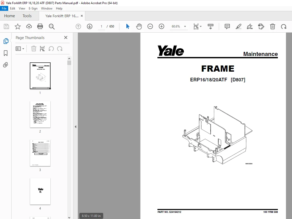
Frame 1
Safety Precautions Maintenance and Repair 2
General 5
Description 5
Overhead Guard Repair 6
Remove 6
Install 7
Hood and Seat Assembly Repair 7
Remove 9
Install 9
Counterweight Repair 9
Remove 9
Install 10
Auxiliary Counterweight Repair 11
Remove 11
Install 11
Hydraulic Tank Repair 12
Inspect 12
Small Leaks, Repair 12
Large Leaks, Repair 12
Clean 12
Steam Method 12
Chemical Solution Method 12
Additional Preparations for Repair 13
Safety Labels 13
Battery Size Specifications 15
tables 1
Table 1 Battery Platform Weights 10
Table 2 Battery Size Specifications – Type: Lead-Acid Battery 15
0620YRM294-524158039(08-2003)-EN 19
toc 19
DC Motor Maintenance 19
Safety Precautions Maintenance and Repair 20
General 23
Brush and Commutator Inspection 23
Hydraulic Pump Motor and Traction Motor 23
Steering Pump Motor 26
Normal Commutator Surface 26
Commutator Problems 26
Brush Replacement 30
Stoning the Commutator 32
Motors Repair 34
Disassemble 34
Traction Motor and Hydraulic Pump Motor 34
Steering Pump Motor 38
Assemble 38
Traction Motor and Hydraulic Pump Motor 38
Steering Pump Motor 39
Brush Alignment, Traction and Hydraulic Motors 42
Tests for Damaged Field and Armature 42
Test for an Open Circuit in Armature 42
Test for Short Circuit in One Armature Winding 43
Test for Short Circuit to Armature Shaft 43
Test for Open Circuit in Field Coil 43
Test for Short Circuit in Field Coil 43
Test for Short Circuit between Field and Motor Case 44
Brush Holder Test 44
Troubleshooting 44
tables 19
Table 1 Normal Commutator Surfaces 25
Table 2 Commutator Problems 26
Table 3 Brush Wear Replacement Guide 30
1300YRM568-524164213(04-2002)-EN 49
toc 49
Transaxle 49
Safety Precautions Maintenance and Repair 50
General 53
Lubrication 54
Transaxle Repair 54
Remove 54
Inspect 55
Install 55
S2 Series Transaxle 56
Disassemble 56
Inspection 58
Assemble 58
General 58
Ring Gear, Install 58
Intermediate Shaft, Install 59
Axle Shaft, Install 59
Pinion Gear, Install 60
Final Assembly 63
S1 Series Transaxle 64
Disassemble 64
Assemble 66
Troubleshooting 67
tables 49
Table 1 Transaxle Identification 53
Table 2 Transaxle Specifications 53
Table 3 Gear Teeth Contact Pattern 62
1600YRM655-524164214(04-2002)-EN 71
toc 71
Steering Housing and Steering Control Unit 71
Safety Precautions Maintenance and Repair 72
General 75
Description 75
Operation 76
Steering Housing Repair 76
Remove and Disassemble 76
Clean 76
Assemble and Install 76
Steering Control Unit Repair 79
Remove 79
Disassemble 79
Clean 79
Assemble 80
Install 80
System Air Removal 80
Troubleshooting 80
1600YRM687-524164215(04-2002)-EN 85
toc 85
Steering System 85
Safety Precautions Maintenance and Repair 86
General 89
Operation 89
Steering Wheel and Column Assembly 90
Description 90
Remove 90
Install 93
Power Steering Pump and Motor 94
Description 94
Remove 94
Install 96
Disassemble 96
Assemble 97
Steering Axle Components 98
General 98
Wheel and Tire Assembly 98
Remove 98
Install 99
Wheel Hub Assembly 99
Remove 99
Install 99
Steering Axle Assembly 99
Remove 99
Clean 100
Install 102
Steering System Air Removal 102
Operation Check 103
Steering Pressure Check 103
Troubleshooting 103
1800YRM570-524164216(04-2002)-EN 109
toc 109
Brake System 109
Safety Precautions Maintenance and Repair 110
General 113
Description 113
Service Brake Pads Repair 113
Remove 113
Install 113
Service Brake Caliper Repair 114
Remove 114
Install 115
Disassemble 115
Assemble 116
Park Brake Caliper Repair 116
Remove 116
Install 116
Disassemble 117
Assemble 117
Master Cylinder Repair 118
Remove 118
Install 118
Disassemble 118
Assemble 119
Foot-Operated Park Brake Lever Assembly Repair 119
Remove 119
Install 121
Electrically Released Park Brake Repair 122
Mechanical Operation 122
Remove 122
Install 125
Electrically Released Park Brake – Electrical Components Repair 126
Control Box 126
Remove 126
Install 126
Terminal Block 126
Remove 126
Install 128
Park Brake Adjustment 128
Service Brake Adjustment 129
Brake System Air Removal 129
Troubleshooting 130
2000YRM576-524164217(04-2002)-EN 135
toc 135
Main Control Valve 135
Safety Precautions Maintenance and Repair 136
General 139
Description 139
Operation 140
Lift Section 141
Tilt Section 141
Tilt Backward 141
Tilt Forward 141
Relief Valve 141
Main Control Valve Repair 141
Remove 141
Install 144
Disassemble 145
Clean and Inspect 147
Assemble 147
Relief Valve Check 148
Vane Settings Adjustment 148
Mast Tilt Adjustment 149
Troubleshooting 150
2100YRM103-524150790(03-2005)-EN 155
toc 155
Tilt Cylinders 155
Safety Precautions Maintenance and Repair 156
General 159
Description 159
Tilt Cylinder Repair 159
Remove 159
Disassemble 159
Clean 159
Assemble 159
Tilt Cylinders With O-Ring or Single-Lip Seals 159
Tilt Cylinders 160
Install 162
Tilt Cylinder Leak Check 164
Tilt Cylinder Stroke and Mast Tilt Angle Adjustment 165
Torque Specifications 165
Piston Rod Nut 165
Retainer 165
Troubleshooting 166
tables 155
Table 1 Movement Rates (Maximum) for Tilt Cylinders 164
2200YRM697-524164218(08-2005)-EN 171
toc 171
SX/SR Transistor Motor Controller and Handset 171
Safety Precautions Maintenance and Repair 172
Introduction to SEM 175
Advantages of Transistorized SEM 175
Features of SEM 176
Solid-State Reversing 176
Performance and Efficiency 176
Field Weakening 176
Regenerative Braking 176
SX Transistor Motor Controllers 177
Introduction 177
Proportional Operation for Dual-Motor Trucks 177
General 177
Operation 179
Controller Features 181
General 181
Creep Speed 181
Controlled Acceleration 181
Current Limit 181
Braking 181
Regenerative Braking to Zero Speed 181
Pedal Position Braking 182
Auto Braking 182
Conventional Plug Braking 182
Auxiliary Speed Control 182
Field Weakening 182
Speed Limits 182
Ramp Operation 182
Ramp Start 182
Antirollback 183
Steer Pump Contactor Time Delay 183
On-Board Coil Drivers and Internal Coil Suppression 183
System Protective Override 183
SRO (Static Return to Off) 183
Accelerator Volts Hold Off 183
Pulse Monitor Trip (PMT) 183
Thermal Protector (TP) 183
Low Voltage 183
SR Lift Pump Controllers 184
Sensor Interface/Contactor Driver Module 188
Diagnostic Status Codes and Troubleshooting 188
General Maintenance Instructions 188
Special Precautions 188
Diagnostics 189
Systems Diagnostics 189
Status Codes 189
Standard Status Codes 189
Stored Status Codes 189
Other Features 190
Hourmeter Readings 190
Maintenance Alert and Speed Limit 190
Battery Discharge Indication (BDI) 190
Internal Resistance Compensation 190
Handset Programmable 190
RS 232 Communication Ports 190
Circuit Board Coil Driver Modules 190
Maintenance Management Capability 190
Interactive Instrument Panel Modes 191
General Troubleshooting Instructions 193
Status Code Troubleshooting Tables 194
SX/SR Handset Instructions 230
General Features 230
Connecting the Handset 232
Startup Sequence 232
Setup Mode 233
Stored Status Code Mode 234
Clearing the Stored Status Codes 234
Restarting Lift Truck 234
SX Traction Controller Function Descriptions 235
Premium Instrument Panel Interactive Modes 242
SR Pump Controller Function Descriptions 244
Premium Instrument Panel Interactive Modes 247
tables 171
Table 1 SX Traction Controller Connections/Descriptions 178
Table 2 SR Lift Pump Controller Connections/Descriptions/Status 185
Table 3 Instrument Panel Function Number Correlation 191
Table 4 Traction Function Settings Logic 192
Table 5 Lift Pump Function Settings Logic 192
Table 6 Speed/Torque Compensation 246
Table 7 Traction Controller Settings – Standard With Auto Regen 249
Table 8 Traction Controller Settings – Standard Without Auto Re 250
Table 9 Traction Controller Settings – High Performance With Au 252
Table 10 Lift Pump Controller Settings 253
2200YRM698 ELECTRICAL SYSTEM-524164219(04-2002)-EN 257
toc 257
Electrical System 257
Safety Precautions Maintenance and Repair 258
General 261
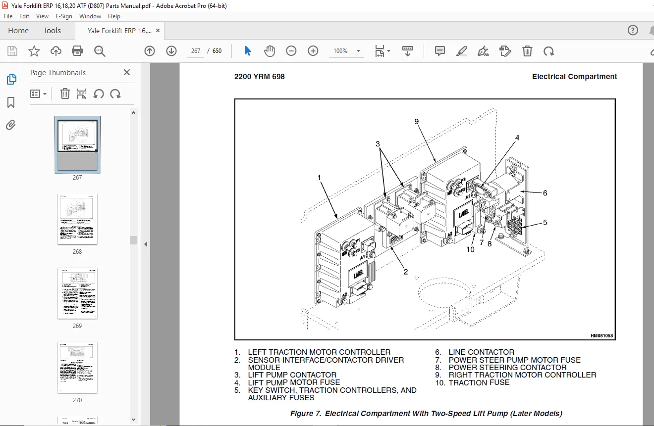
Electrical Compartment 262
Instrument Panels 268
Standard Display (Current Configuration) 268
Premium Display (Current Configuration) 269
Replacement (Current Configuration) 270
Control and Power Fuses 271
Steer Angle Potentiometer 271
General 271
Operation 271
Example 272
Installation 273
Positioning Steer Tire for Straight Travel 273
Adjustment 273
Handset Method 274
Voltmeter Method 274
Testing 276
Power Steering Control Assembly 276
General 276
Operation 276
Testing 277
Removal and Replacement 279
Power Steering Control Assembly 279
Optical Encoder 279
Lift Pump Control Board 280
General 280
Testing 280
Bypassing Lift Pump Control Board 284
Sensor Interface/Contactor Driver Module 284
General 284
Troubleshooting 286
Other Control Components 287
Key Switch 288
Seat Switch 288
Replace 289
Parking Brake Switch 289
Check 289
Replace 290
Accelerator Switch Assembly 290
Check 291
Replace 291
Direction Switches ( Foot Directional Control Pedal) 291
Check 291
Replace 291
Direction Switches (Steering Column) 292
Check 292
Replace 292
Brake Fluid Switch 292
Hydraulic Cutoff Switch 292
Check 293
Replace 293
Stop Light Switch 293
Check 293
Replace 294
Motor Temperature Switches 294
Rocker Switches for Lights 294
DC-to-DC Converter 295
Backup Light Relay Panel 295
Backup Light Switch Relay 296
Horn and Horn Button 296
Horn 296
Horn Switch and Cover (Button) 297
Lights and Reverse Alarm 297
Light Assemblies Replacement 299
Tail Light 299
Flashing Light Assembly 299
Front Driving Light and Rear Work Light Assemblies 300
Spot Light Assembly 303
tables 257
Table 1 Potentiometer Specifications 276
Table 2 Power Steering Control Assembly Specifications 277
Table 3 Lift Pump Control Board Test Point/Function Relationshi 281
Table 4 Lift Pump Control Board Troubleshooting Guide 282
Table 5 Lift Pump Control Board Test Values 283
Table 6 Lift Pump Control Board Bypass Test 284
Table 7 SICDM Connections/Descriptions/Status Codes 285
2200YRM779-524164220(06-2005)-EN 307
toc 307
SR/SP Transistor Motor Controller and Handset 307
Safety Precautions Maintenance and Repair 308
Introduction to SEM 311
Advantages of Transistorized SEM 311
Features of SEM 311
Solid-State Reversing 311
Performance and Efficiency 311
Field Weakening 311
Regenerative Braking 311
SR Transistor Traction Motor Controllers 312
Introduction 312
Proportional Operation for Dual-Motor Trucks 312
General 312
Operation 315
Controller Features 315
General 315
Creep Speed 315
Controlled Acceleration 316
Current Limit 316
Braking 316
Regenerative Braking to Zero Speed 316
Pedal Position Braking 316
Auto Regenerative Braking 316
Conventional Plug Braking 316
Auxiliary Speed Control 317
Field Weakening 317
Speed Limits 317
Ramp Operation 317
Ramp Start 317
Antirollback 317
Steer Pump Contactor Time Delay 317
On-Board Coil Drivers and Internal Coil Suppression 317
System Protective Override 317
SRO (Static Return to Off) 317
Accelerator Volts Hold Off 317
Pulse Monitor Trip (PMT) 318
Thermal Protector (TP) 318
Low Voltage 318
SP Lift Pump Controllers 318
Sensor Interface/Contactor Driver Module 322
Diagnostic Status Codes and Troubleshooting 322
General Maintenance Instructions 322
Special Precautions 322
Diagnostics 323
Systems Diagnostics 323
Status Codes 323
Standard Status Codes 323
Stored Status Codes 324
Other Features 324
Hourmeter Readings 324
Maintenance Alert and Speed Limit 324
Battery Discharge Indication (BDI) 324
Internal Resistance Compensation 324
Handset Programmable 324
RS 232 Communication Ports 324
Circuit Board Coil Driver Modules 324
Maintenance Management Capability 325
Interactive Instrument Panel Modes (Premium Only) 325
General Troubleshooting Instructions 327
Status Code Troubleshooting Tables 328
Description 328
SR/SP Handset Instructions 366
General Features 366
Connecting Handset 368
Startup Sequence 369
Setup Mode 370
Stored Status Code Mode 370
Clearing Stored Status Codes 371
Restarting Lift Truck 371
SR Traction Controller Function Descriptions 372
Premium Instrument Panel Interactive Modes 378
SP Pump Controller Function Descriptions 381
Premium Instrument Panel Interactive Modes 384
tables 307
Table 1 SR Traction Controller Connections/Descriptions 314
Table 2 SP Lift Pump Controller Connections/Descriptions/Status 319
Table 3 Instrument Panel Function Number Correlation 325
Table 4 Traction Function Settings Logic 326
Table 5 Lift Pump Function Settings Logic 327
Table 6 Speed/Torque Compensation 383
2240YRM001-524158040(11-2003)-EN 389
toc 389
Industrial Battery 389
Safety Precautions Maintenance and Repair 390
General 393
Lead-Acid Batteries 393
Specific Gravity 394
Chemical Reaction in a Cell 394
Electrical Terms 395
Battery Selection 396
Battery Voltage 397
Battery as a Counterweight 397
Battery Ratings 397
Kilowatt-Hours 397
Battery Maintenance 398
Safety Procedures 398
Maintenance Records 398
New Battery 398
Cleaning Battery 399
Adding Water to Battery 400
Hydrometer 401
Battery Temperature 401
Charging Battery 402
Types of Battery Charges 403
Methods of Charging 404
Troubleshooting Charger 404
Knowing When Battery Is Fully Charged 405
Where to Charge Batteries 405
Equipment Needed 405
Battery Connectors 405
Battery Care 406
tables 389
Table 1 Battery Capacity Terms 397
4000YRM521-524158890(05-2004)-EN 411
toc 411
Mast 411
Safety Precautions Maintenance and Repair 412
General 415
Description and Operation 415
Carriages 415
Mast Mounts 417
Two-Stage Mast, Limited Free-Lift (LFL) 418
Description and Operation 418
Two-Stage Mast, Full Free-Lift (FFL) 420
Description and Operation 420
Three-Stage Mast, Full Free-Lift (FFL) 422
Description and Operation 422
Cylinder Cushion During Lifting Sequence 425
Cylinder Cushion During Lowering Sequence 426
4000YRM522-524158891(05-2004)-EN 429
toc 429
Mast 429
Safety Precautions Maintenance and Repair 430
General 433
Safety Procedures When Working Near Mast 433
Forks Repair 435
Remove 435
Install 435
Carriages Repair 436
Standard Carriage, Remove 436
Hang-On Sideshift Carriage, Remove 437
Standard Carriage and Hang-On Sideshift Carriage, Repair 438
Standard Carriage, Install 438
Hang-On Sideshift Carriage, Install 439
Integral Sideshift Carriage 439
Remove 439
Clean and Inspect 441
Repair 441
Install 442
Mast Repair 442
Remove 442
Two-Stage LFL and Two-Stage FFL Masts, Disassemble 444
Three-Stage FFL Mast 451
Disassemble 451
Mast and Chains, Clean and Inspect 454
Two-Stage LFL and Two-Stage FFL Mast, Assemble 455
Three-Stage FFL Mast, Assemble 456
Install 457
Lift Cylinders Repair 459
Main Lift Cylinders, Remove 459
Free-Lift Cylinder, Remove 459
Lift Cylinders, Disassemble 460
Lift Cylinders, Assemble 461
Main Lift Cylinders, Install 463
Free-Lift Cylinder, Install 463
Header Hose Arrangements 464
Two-Stage LFL Mast, New Hose Install 464
Two-Stage LFL Mast, Adjust Hoses After Installation 469
Two-Stage FFL Mast, New Hose Install 469
Two-Stage FFL Mast, Adjust Hoses After Installation 474
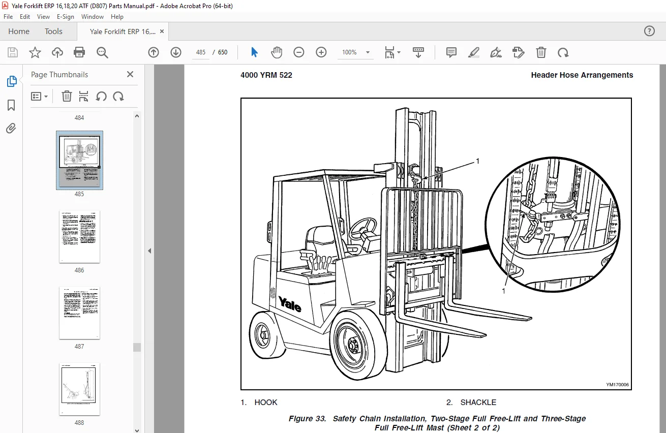
Three-Stage FFL Mast, New Hose Install 474
Three-Stage FFL Mast, Adjust Hoses After Installation 486
Header Hose Arrangement 487
Two-Stage LFL Mast, New Hose Install 487
Two-Stage LFL Mast, Adjust Hoses After Installation 491
Two-Stage FFL Mast, New Hose Install 491
Two-Stage FFL Mast, Adjust Hoses After Installation 496
Three-Stage FFL Mast, New Hose Install 498
Three-Stage FFL Mast, Adjust Hoses After Install 506
Lift and Tilt System Leak Check 506
Lift Cylinders Leak Check 506
Tilt Cylinders Leak Check 506
Tilt Cylinders Adjustment 507
Lift Chains Adjustment 508
Mast Adjustment 510
Carriage Adjustment 512
Troubleshooting 512
tables 429
Table 1 Hook-Type Carriage Chain Adjustment 509
Table 2 Pin-Type Carriage Chain Adjustment 509
8000YRM231-524150797(12-2004)-EN 517
toc 517
Metric and Inch (SAE) Fasteners 517
Safety Precautions Maintenance and Repair 518
General 521
Threaded Fasteners 521
Nomenclature, Threads 521
Strength Identification 522
Cotter (Split) Pins 522
Fastener Torque Tables 527
Conversion Table 529
tables 517
Table 1 Bolts and Screws 523
Table 2 Studs and Nuts 524
Table 3 Torque Nuts 525
Table 4 Torque Nuts with Nylon Insert 526
Table 5 Torque Values for Metric Fasteners* 527
Table 6 Torque Values for Inch Fasteners* 528
Table 7 Conversion Table for Metric and English Units 529
Table 8 Cotter Pin Dimensional Data 530
Table 9 Cotter Pin Dimensional Data 531
Table 10 Cotter Pin Dimensional Data 532
Table 11 Cotter Pin Dimensional Data 534
8000YRM586-524164221(04-2002)-EN 537
toc 537
Capacities and Specifications 537
Safety Precautions Maintenance and Repair 538
Wheels and Tires 541
Motors (Dual Voltage 36/48) 541
Mast Tilt Performance 541
Mast Speeds 542
19cc Pump One- and Two-Speed Contactor 542
19cc Pump Transistor Control 543
12cc Pump One- and Two-Speed Contactor 544
12cc Pump Transistor Control 545
Mast/Tilt Drift Speeds 545
Hydraulic System 546
Torque Specifications 546
Frame 546
Transaxle 546
Brake System 546
Wheels 546
Steering System 547
Hydraulic System 547
Mast/Tilt/Attachment Systems 547
Accelerator Potentiometer Checks 547
Adjustments 548
EV 100 LX Traction Card 548
EV 100 LX Pump Card 548
Controller Settings 549
SR/SP Traction Controller Settings – Standard With Auto Regen 549
SR/SP Traction Controller Settings – Standard Without Auto Decel 551
SR/SP Lift Pump Controller Settings 552
SR/SP Traction Controller Settings – 36V Energy Option 553
Battery Size Specifications 554
Type: Lead Acid Battery 554
8000YRM696 DIAGRAMS-524164222(04-2002)-EN 559
toc 559
Diagrams 559
Safety Precautions Maintenance and Repair 560
8000YRM699-524164223(04-2002)-EN 605
toc 605
Periodic Maintenance 605
Safety Precautions Maintenance and Repair 606
General 609
How to Move Disabled Lift Truck 609
How to Tow Lift Truck 609
How to Put Lift Truck on Blocks 610
How to Raise Load Wheels 610
How to Raise Steer Wheel 610
Maintenance Schedule 611
Maintenance Procedures Every 8 Hours or Daily 615
Before Operation Checks 615
Hydraulic System 615
Battery 616
Battery Restraint System 616
Tires and Wheels 617
Safety Procedures When Working Near Mast 618
Forks 620
Adjust 620
Remove 620
Inspect 621
Install 622
Mast and Lift Chains 622
Lift Chain, Adjustment 622
Operation Check 623
Gauges and Horn 623
Control Levers and Pedals 623
Service Brakes 624
Parking Brake 624
Steering System 624
Maintenance Procedures Every 350 Hours or 3 Months 624
Hydraulic Tank Breather 624
Wheel Nut Torque 624
Transaxle 624
Lift System Operation 625
Mast 625
Lift Chains 626
Forks 627
Safety Labels 627
Brake Fluid 627
Other Lubrication 627
Electrical Inspection 627
Special Precautions 627
Contactors 628
Motor Brushes 628
Parking Brake 628
Maintenance Procedures Every 2000 Hours or Yearly 631
Hydraulic System 631
Hydraulic Oil Filter, Change 631
Hydraulic Oil Strainer, Check 631
Hydraulic Oil, Change 631
Brakes 632
Parking Brake, Adjust 632
Transaxle 633
Maintenance Procedures Every 4000 Hours 634
Transaxle 634
Lift and Tilt System Leak Check 634
Lift System 634
Tilt System 635
Battery Maintenance 635
How to Charge Battery 635
How to Change Battery 636
Battery Size Specifications 637
Wheels and Tires Maintenance 638
General 638
How to Change Tires 638
Steer and Drive Wheels 638
Pneumatic Tires 639
Remove Wheel From Lift Truck 639
Tire Sizes and Pressures 639
Remove Tire From Wheel 640
Install Tire on Wheel 641
Add Air to Tires 642
Pneumatic-Shaped Solid Tires 642
Remove Wheel From Lift Truck 642
Press Tire From Wheel 643
Install Tire on Wheel 644
Install Wheel and Tire 646
tables 605
Table 1 Maintenance Schedule 612
Table 2 Transaxle Capacity 633
Table 3 Battery Size Specifications – Type: Lead-Acid Battery 637
D807 Index 649
D807 649
S.V 07/24