![Yale Forklift ERP030/035/040TGN [E807] Maintenance Manual - PDF DOWNLOAD](https://heydownloads.com/wp-content/uploads/2024/07/Yale-Forklift-ERP030-035-040TGN-E807-Maintenance-Manual-3.webp)
![Yale Forklift ERP030/035/040TGN [E807] Maintenance Manual - PDF DOWNLOAD - Image 2](https://heydownloads.com/wp-content/uploads/2024/07/Yale-Forklift-ERP030-035-040TGN-E807-Maintenance-Manual-1.webp)
![Yale Forklift ERP030/035/040TGN [E807] Maintenance Manual - PDF DOWNLOAD - Image 3](https://heydownloads.com/wp-content/uploads/2024/07/Yale-Forklift-ERP030-035-040TGN-E807-Maintenance-Manual-2.webp)
Yale Forklift ERP030/035/040TGN [E807] Maintenance Manual – PDF DOWNLOAD
$31.95
Yale Forklift ERP030/035/040TGN [E807] Maintenance Manual – PDF DOWNLOAD
Description
Yale Forklift ERP030/035/040TGN [E807] Maintenance Manual – PDF DOWNLOAD
FILE DETAILS:
Yale Forklift ERP030/035/040TGN [E807] Maintenance Manual – PDF DOWNLOAD
Language : English
Pages : 620
Downloadable : Yes
File Type : PDF
IMAGES PREVIEW OF THE MANUAL:
TABLE OF CONTENTS:
Yale Forklift ERP030/035/040TGN [E807] Maintenance Manual – PDF DOWNLOAD
toc 1
Capacities and Specifications 1
Safety Precautions Maintenance and Repair 2
Wheels and Tires 5
Motors (Dual Voltage 36/48) 5
Mast Tilt Performance 5
Mast Speeds 6
Contactor Controlled 19cc/rev Displacement Pump 6
Transistor Controlled 19cc/rev Displacement Pump 7
Contactor Controlled 12cc Displacement Pump 8
Transistor Controlled 12cc/rev Displacement Pump 9
Mast/Tilt Drift Speeds 9
Hydraulic System 10
Torque Specifications 10
Frame 10
Transaxle 10
Brake System 10
Wheels 10
Steering System 11
Hydraulic System 11
Mast/Tilt/Attachment Systems 11
Accelerator Potentiometer Checks 11
Controller Settings 12
SR/SP Traction Controller Settings – Standard 12
SR/SP Traction Controller Settings – 36 V Energy Saver Option 13
SR/SP Traction Controller Settings – With or Without Auto Decele 14
SR/SP Traction Controller Settings – With or Without Lift Limit 14
SR/SP Lift Pump Controller Settings 14
Battery Size Specifications 15
Type: Lead Acid Battery 15
toc 19
DC Motor Maintenance 19
Safety Precautions Maintenance and Repair 20
General 23
Brush and Commutator Inspection 23
Hydraulic Pump Motor and Traction Motor 23
Steering Pump Motor 26
Normal Commutator Surface 26
Commutator Problems 26
Brush Replacement 30
Stoning the Commutator 32
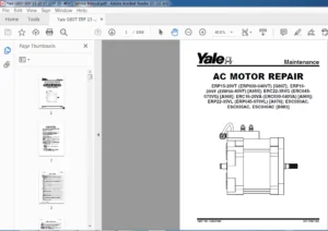
Motors Repair 34
Disassemble 34
Traction Motor and Hydraulic Pump Motor 34
Steering Pump Motor 38
Assemble 38
Traction Motor and Hydraulic Pump Motor 38
Steering Pump Motor 39
Brush Alignment, Traction and Hydraulic Motors 42
Tests for Damaged Field and Armature 42
Test for an Open Circuit in Armature 42
Test for Short Circuit in One Armature Winding 43
Test for Short Circuit to Armature Shaft 43
Test for Open Circuit in Field Coil 43
Test for Short Circuit in Field Coil 43
Test for Short Circuit between Field and Motor Case 44
Brush Holder Test 44
Troubleshooting 44
tables 19
Table 1 Normal Commutator Surfaces 25
Table 2 Commutator Problems 26
Table 3 Brush Wear Replacement Guide 30
toc 49
Diagrams 49
Safety Precautions Maintenance and Repair 50
toc 81
Electrical System 81
Safety Precautions Maintenance and Repair 82
General 85
Instrument Panels 86
Standard Display 86
Premium Display 87
Replace 88
Control and Power Fuses 88
Steer Angle Potentiometer 89
General 89
Operation 89
Install 89
Positioning Steer Tire for Straight Travel 90
Adjust 91
Handset Method 91
Voltmeter Method 92
Testing 93
Power Steering Control Assembly 93
General 93
Operation 93
Testing 94
Remove and Replace 96
Power Steering Control Assembly 96
Optical Encoder 96
Lift Pump Control Board 97
Testing 104
Bypassing Lift Pump Control Board 107
Sensor Interface/Contactor Driver Module 107
General 107
Troubleshooting 109
Other Control Components 110
Key Switch 111
Seat Switch 111
Replace 111
Parking Brake Switch 112
Check 112
Replace 112
Accelerator Switch Assembly 112
Check 113
Replace 113
Direction Switches ( Foot Directional Control Pedal) 114
Check 114
Replace 114
Direction Switches (Steering Column) 114
Check 115
Replace 115
Brake Fluid Switch 115
Hydraulic Cutoff Switch 115
Check 116
Replace 116
Stop Light Switch 116
Check 116
Replace 117
Motor Temperature Switches 117
Rocker Switches for Lights 117
DC-to-DC Converter 118
Backup Light Relay Panel 118
Backup Light Switch Relay 118
Horn and Horn Button 119
Horn, Replace 119
Horn Button, Replace 120
Lights and Reverse Alarm 120
Light Assemblies Replacement 122
Tail Light 122
Flashing Light Assembly 123
Front Driving Light and Rear Work Light Assemblies 125
Spot Light Assembly 125
tables 81
Table 1 Potentiometer Specifications 93
Table 2 Power Steering Control Assembly Specifications 96
Table 3 Lift Pump Control Board Test Point/Function Relationshi 104
Table 4 Lift Pump Control Board Troubleshooting Guide 105
Table 5 Lift Pump Control Board Test Values 106
Table 6 Lift Pump Control Board Bypass Test 107
Table 7 SICDM Connections/Descriptions/Status Codes 108
toc 129
Frame 129
Safety Precautions Maintenance and Repair 130
General 133
Description 133
Overhead Guard Repair 135
Remove 135
Install 136
Hood and Seat Assembly Repair 136
Remove 137
Install 137
Counterweight Repair 138
Remove 138
Install 139
Hydraulic Tank Repair 139
Inspect 139
Small Leaks, Repair 139
Large Leaks, Repair 139
Clean 139
Steam Method 140
Chemical Solution Method 140
Additional Preparations for Repair 140
Safety Labels 141
Battery Specifications 143
tables 129
Table 1 Battery Platform Weights 138
Table 2 ERP030TGN Truck Capacity 1600 kg ( 3500 lb) – Wheel Bas 143
Table 3 ERP035TGN Truck Capacity 1800 kg ( 4000 lb) – Wheel Bas 144
Table 4 ERP040TGN Truck Capacity 2000 kg ( 4400 lb) – Wheel Bas 144
toc 147
Industrial Battery 147
Safety Precautions Maintenance and Repair 148
General 151
Lead-Acid Batteries 151
Specific Gravity 152
Chemical Reaction in a Cell 152
Electrical Terms 153
Battery Selection 154
Battery Voltage 155
Battery as a Counterweight 155
Battery Ratings 155
Kilowatt-Hours 155
Battery Maintenance 156
Safety Procedures 156
Maintenance Records 156
New Battery 156
Cleaning Battery 157
Adding Water to Battery 158
Hydrometer 158
Battery Temperature 159
Charging Battery 160
Types of Battery Charges 161
Methods of Charging 162
Troubleshooting Charger 162
Knowing When Battery Is Fully Charged 163
Where to Charge Batteries 163
Equipment Needed 163
Battery Connectors 163
Battery Care 164
tables 147
Table 1 Battery Capacity Terms 155
toc 169
Main Control Valve 169
Safety Precautions Maintenance and Repair 170
General 173
Description 173
Operation 174
Lift Section 175
Tilt Section 175
Tilt Backward 175
Tilt Forward 175
Relief Valve 175
Main Control Valve Repair 176
Remove 176
Install 176
Disassemble 177
Clean and Inspect 179
Assemble 183
Relief Valve Check 183
Vane Settings Adjustment 184
Mast Tilt Adjustment 184
Troubleshooting 185
toc 191
Mast 191
Safety Precautions Maintenance and Repair 192
General 195
Description and Operation 195
Carriages 195
Mast Mounts 197
Two-Stage Mast, Limited Free-Lift (LFL) 198
Description and Operation 198
Two-Stage Mast, Full Free-Lift (FFL) 200
Description and Operation 200
Three-Stage Mast, Full Free-Lift (FFL) 202
Description and Operation 202
Cylinder Cushion During Lifting Sequence 205
Cylinder Cushion During Lowering Sequence 206
toc 209
Mast 209
Safety Precautions Maintenance and Repair 210
General 213
Safety Procedures When Working Near Mast 213
Forks Repair 215
Remove 215
Install 215
Carriages Repair 216
Standard Carriage, Remove 216
Hang-On Sideshift Carriage, Remove 217
Standard Carriage and Hang-On Sideshift Carriage, Repair 217
Standard Carriage, Install 219
Hang-On Sideshift Carriage, Install 219
Integral Sideshift Carriage 220
Remove 220
Clean and Inspect 221
Repair 221
Install 222
Mast Repair 222
Remove 222
Two-Stage LFL and Two-Stage FFL Masts, Disassemble 223
Three-Stage FFL Mast 230
Disassemble 230
Mast and Chains, Clean and Inspect 233
Two-Stage LFL and Two-Stage FFL Mast, Assemble 234
Three-Stage FFL Mast, Assemble 236
Install 237
Lift Cylinders Repair 238
Main Lift Cylinders, Remove 238
Free-Lift Cylinder, Remove 238
Lift Cylinders, Disassemble 239
Lift Cylinders, Assemble 241
Main Lift Cylinders, Install 242
Free-Lift Cylinder, Install 242
Header Hose Arrangements 243
Two-Stage LFL Mast, New Hose Install 243
Two-Stage LFL Mast, Adjust Hoses After Installation 248
Two-Stage FFL Mast, New Hose Install 248
Two-Stage FFL Mast, Adjust Hoses After Installation 255
Three-Stage FFL Mast, New Hose Install 255
Three-Stage FFL Mast, Adjust Hoses After Installation 267
Header Hose Arrangement 267
Two-Stage LFL Mast, New Hose Install 267
Two-Stage LFL Mast, Adjust Hoses After Installation 271
Two-Stage FFL Mast, New Hose Install 271
Two-Stage FFL Mast, Adjust Hoses After Installation 276
Three-Stage FFL Mast, New Hose Install 278
Three-Stage FFL Mast, Adjust Hoses After Install 282
Lift and Tilt System Leak Check 286
Lift Cylinders Leak Check 286
Tilt Cylinders Leak Check 286
Tilt Cylinders Adjustment 286
Lift Chains Adjustment 288
Mast Adjustment 289
Carriage Adjustment 291
Troubleshooting 292
tables 209
Table 1 Hook-Type Carriage Chain Adjustment 288
Table 2 Pin-Type Carriage Chain Adjustment 289
toc 295
Periodic Maintenance 295
Safety Precautions Maintenance and Repair 296
General 299
How to Move Disabled Lift Truck 299
How to Tow Lift Truck 299
How to Put Lift Truck on Blocks 300
How to Raise Drive Tires 300
How to Raise Steer Tires 301
Maintenance Schedule 302
Maintenance Procedures Every 8 Hours or Daily 306
Before Operation Checks 306
Hydraulic System 306
Battery 307
Battery Restraint System 307
Tires and Wheels 308
Safety Procedures When Working Near Mast 309
Forks 311
Adjust 311
Remove 312
Inspect 312
Install 312
Mast and Lift Chains 313
Lift Chain, Adjustment 314
Operation Check 315
Gauges and Horn 315
Control Levers and Pedals 315
Service Brakes 315
Parking Brake 315
Steering System 315
Maintenance Procedures Every 350 Hours or 3 Months 316
Hydraulic Tank Breather 316
Wheel Nut Torque 316
Steering Actuator Mounting Bolts 316
Transaxle 316
Lift System Operation 317
Mast 317
Lift Chains 319
Forks 319
Safety Labels 320
Brake Fluid 320
Other Lubrication 320
Electrical Inspection 320
Special Precautions 320
Contactors 321
Motor Brushes 321
Parking Brake 321
Maintenance Procedures Every 2000 Hours or Yearly 328
Hydraulic System 328
Hydraulic Oil Filter, Change 328
Hydraulic Oil Strainer, Check 328
Hydraulic Oil, Change 328
Brakes 329
Parking Brake, Adjust 329
Transaxle 330
Maintenance Procedures Every 4000 Hours 331
Transaxle 331
Lift and Tilt System Leak Check 331
Lift System 331
Tilt System 332
Battery Maintenance 332
How to Charge Battery 332
How to Change Battery 333
Battery Size Specifications 334
Wheels and Tires Maintenance 335
General 335
How to Change Tires 335
Steer and Drive Wheels 335
Pneumatic Tires 335
Remove Wheel From Lift Truck 335
Tire Sizes and Pressures 336
Remove Tire From Wheel 337
Install Tire on Wheel 338
Add Air to Tires 339
Pneumatic-Shaped Solid Tires 339
Remove Wheel From Lift Truck 339
Press Tire From Wheel 340
Install Tire on Wheel 341
Install Wheel and Tire 343
tables 295
Table 1 Maintenance Schedule 303
Table 2 Transaxle Specifications 330
Table 3 Battery Size Specifications – Type: Lead-Acid Battery 334
toc 347
SR/SP Transistor Motor Controller and Handset 347
Safety Precautions Maintenance and Repair 348
Introduction to SEM 351
Advantages of Transistorized SEM 351
Features of SEM 351
Solid-State Reversing 351
Performance and Efficiency 351
Field Weakening 351
Regenerative Braking 351
SR Transistor Traction Motor Controllers 352
Introduction 352
Proportional Operation for Dual-Motor Trucks 352
General 352
Operation 354
Controller Features 356
General 356
Creep Speed 356
Controlled Acceleration 356
Current Limit 356
Braking 356
Regenerative Braking to Zero Speed 356
Pedal Position Braking 356
Auto Regenerative Braking 357
Conventional Plug Braking 357
Auxiliary Speed Control 357
Field Weakening 357
Speed Limits 357
Ramp Operation 357
Ramp Start 357
Antirollback 357
Steer Pump Contactor Time Delay 357
On-Board Coil Drivers and Internal Coil Suppression 358
System Protective Override 358
SRO (Static Return to Off) 358
Accelerator Volts Hold Off 358
Pulse Monitor Trip (PMT) 358
Thermal Protector (TP) 358
Low Voltage 358
SP Lift Pump Controllers 358
Sensor Interface/Contactor Driver Module 363
Diagnostic Status Codes and Troubleshooting 363
General Maintenance Instructions 363
Special Precautions 363
Diagnostics 364
Systems Diagnostics 364
Status Codes 364
Standard Status Codes 364
Stored Status Codes 365
Other Features 365
Hourmeter Readings 365
Maintenance Alert and Speed Limit 365
Battery Discharge Indication (BDI) 365
Internal Resistance Compensation 365
Handset Programmable 365
RS 232 Communication Ports 365
Circuit Board Coil Driver Modules 365
Maintenance Management Capability 366
Interactive Instrument Panel Modes (Premium Only) 366
General Troubleshooting Instructions 368
Status Code Troubleshooting Tables 370
SR/SP Handset Instructions 407
General Features 407
Connecting Handset 409
Startup Sequence 410
Setup Mode 410
Stored Status Code Mode 411
Clearing Stored Status Codes 412
Restarting Lift Truck 412
SR Traction Controller Function Descriptions 412
Premium Instrument Panel Interactive Modes 419
SP Pump Controller Function Descriptions 422
Premium Instrument Panel Interactive Modes 424
tables 347
Table 1 SR Traction Controller Connections/Descriptions 353
Table 2 SP Lift Pump Controller Connections/Descriptions/Status 360
Table 3 Instrument Panel Function Number Correlation 366
Table 4 Traction Function Settings Logic 367
Table 5 Lift Pump Function Settings Logic 368
Table 6 Speed/Torque Compensation 424
toc 429
Steering Housing and Steering Control Unit 429
Safety Precautions Maintenance and Repair 430
General 433
Description 433
Operation 434
Steering Housing Repair 434
Remove and Disassemble 434
Clean 434
Assemble and Install 436
Steering Control Unit Repair 436
Remove 436
Disassemble 436
Clean 436
Assemble 438
Install 438
System Air Removal 438
Troubleshooting 439
toc 443
Steering System 443
Safety Precautions Maintenance and Repair 444
General 447
Operation 447
Steering Wheel and Column Assembly 448
Description 448
Remove 448
Install 451
Power Steering Pump and Motor 452
Description 452
Remove 452
Install 452
Disassemble 454
Assemble 454
Steering Axle Components 456
General 456
Wheel and Tire Assembly 456
Remove 456
Install 456
Wheel Hub Assembly 456
Remove 456
Install 457
Steering Axle Assembly 457
Remove 457
Clean 458
Install 458
Steering System Air Removal 460
Operation Check 460
Steering Pressure Check 461
Troubleshooting 462
toc 469
SX/SR Transistor Motor Controller and Handset 469
Safety Precautions Maintenance and Repair 470
Introduction to SEM 473
Advantages of Transistorized SEM 473
Features of SEM 474
Solid-State Reversing 474
Performance and Efficiency 474
Field Weakening 474
Regenerative Braking 474
SX Transistor Motor Controllers 475
Introduction 475
Proportional Operation for Dual-Motor Trucks 475
General 475
Operation 477
Controller Features 479
General 479
Creep Speed 479
Controlled Acceleration 479
Current Limit 479
Braking 479
Regenerative Braking to Zero Speed 479
Pedal Position Braking 479
Auto Braking 480
Conventional Plug Braking 480
Auxiliary Speed Control 480
Field Weakening 480
Speed Limits 480
Ramp Operation 480
Ramp Start 480
Antirollback 480
Steer Pump Contactor Time Delay 481
On-Board Coil Drivers and Internal Coil Suppression 481
System Protective Override 481
SRO (Static Return to Off) 481
Accelerator Volts Hold Off 481
Pulse Monitor Trip (PMT) 481
Thermal Protector (TP) 481
Low Voltage 481
SR Lift Pump Controllers 482
Sensor Interface/Contactor Driver Module 486
Diagnostic Status Codes and Troubleshooting 486
General Maintenance Instructions 486
Special Precautions 486
Diagnostics 487
Systems Diagnostics 487
Status Codes 487
Standard Status Codes 487
Stored Status Codes 487
Other Features 488
Hourmeter Readings 488
Maintenance Alert and Speed Limit 488
Battery Discharge Indication (BDI) 488
Internal Resistance Compensation 488
Handset Programmable 488
RS 232 Communication Ports 488
Circuit Board Coil Driver Modules 488
Maintenance Management Capability 488
Interactive Instrument Panel Modes 489
General Troubleshooting Instructions 491
Status Code Troubleshooting Tables 493
SX/SR Handset Instructions 529
General Features 529
Connecting the Handset 531
Startup Sequence 531
Setup Mode 532
Stored Status Code Mode 533
Clearing the Stored Status Codes 533
Restarting Lift Truck 533
SX Traction Controller Function Descriptions 534
Premium Instrument Panel Interactive Modes 541
SR Pump Controller Function Descriptions 543
Premium Instrument Panel Interactive Modes 546
tables 469
Table 1 SX Traction Controller Connections/Descriptions 476
Table 2 SR Lift Pump Controller Connections/Descriptions/Status 483
Table 3 Instrument Panel Function Number Correlation 489
Table 4 Traction Function Settings Logic 490
Table 5 Lift Pump Function Settings Logic 491
Table 6 Speed/Torque Compensation 545
Table 7 Traction Controller Settings – Standard With Auto Regen 548
Table 8 Traction Controller Settings – Standard Without Auto Re 549
Table 9 Traction Controller Settings – High Performance With Au 551
Table 10 Lift Pump Controller Settings 552
toc 557
Tilt Cylinders 557
Safety Precautions Maintenance and Repair 558
General 561
Description 561
Tilt Cylinder Repair 561
Remove 561
Disassemble 561
Clean 561
Assemble 562
Tilt Cylinders With O-Ring or Single-Lip Seals 562
Tilt Cylinders 563
Install 564
Tilt Cylinder Leak Check 565
Tilt Cylinder Stroke and Mast Tilt Angle Adjustment 566
Torque Specifications 566
Piston Rod Nut 566
Retainer 566
Troubleshooting 567
tables 557
Table 1 Movement Rates (Maximum) for Tilt Cylinders 565
toc 571
Transaxle 571
Safety Precautions Maintenance and Repair 572
General 575
Lubrication 576
Transaxle Repair 576
Remove 576
Inspect 577
Install 577
S2 Series Transaxle 578
Disassemble 578
Inspection 579
Assemble 579
General 579
Ring Gear, Install 579
Intermediate Shaft, Install 579
Axle Shaft, Install 582
Pinion Gear, Install 582
Final Assembly 586
S1 Series Transaxle 587
Disassemble 587
Assemble 587
Troubleshooting 590
tables 571
Table 1 Transaxle Identification 575
Table 2 Transaxle Specifications 575
Table 3 Gear Teeth Contact Pattern 585
toc 593
Brake System 593
Safety Precautions Maintenance and Repair 594
General 597
Description 597
Service Brake Pads Repair 597
Remove 597
Install 597
Service Brake Caliper Repair 599
Remove 599
Install 600
Disassemble 600
Assemble 600
Park Brake Caliper Repair 601
Remove 601
Install 602
Disassemble 602
Assemble 602
Master Cylinder Repair 602
Remove 602
Install 603
Disassemble 603
Assemble 604
Foot-Operated Park Brake Lever Assembly Repair 604
Remove 604
Install 606
Electrically Released Park Brake Repair 607
Mechanical Operation 607
Remove 607
Install 609
Electrically Released Park Brake – Electrical Components Repair 611
Control Box 611
Remove 611
Install 611
Terminal Block 613
Remove 613
Install 613
Park Brake Adjustment 615
Service Brake Adjustment 616
Brake System Air Removal 616
Troubleshooting 617
S.V 07/24