Yale Forklift GLP/GDP 16/20 AF (B810) Service Manual – PDF DOWNLOAD
$31.95
Yale Forklift GLP/GDP 16/20 AF (B810) Service Manual – PDF DOWNLOAD
Description
Yale Forklift GLP/GDP 16/20 AF (B810) Service Manual – PDF DOWNLOAD
FILE DETAILS:
Yale Forklift GLP/GDP 16/20 AF (B810) Service Manual – PDF DOWNLOAD
Language : English
Pages : 654
Downloadable : Yes
File Type : PDF
IMAGES PREVIEW OF THE MANUAL:
TABLE OF CONTENTS:
Yale Forklift GLP/GDP 16/20 AF (B810) Service Manual – PDF DOWNLOAD
0100YRM545-524168415(06-2004)-EN FRAME 1
toc 1
Frame 1
Safety Precautions Maintenance and Repair 2
General 5
Description 5
Operator Module Repair 5
Remove 5
Install 7
Hood and Side Covers Repair 8
Remove 8
Install 9
Overhead Guard Repair 10
Remove and Install 10
LED Backup and Brake Lights, Replace 10
Remove 10
Install 10
Counterweight Repair 11
Remove 12
Install 13
Exhaust System Repair 13
Muffler, Replace 13
Radiator and Cooling System Repair 17
Remove 17
Install 17
Operator Restraint System Repair 18
Engine Repair 19
Remove (Engine Only) 19
Remove (Engine and Transmission) 20
Install (Engine Only) 20
Install (Engine and Transmission) 21
Fuel and Hydraulic Tanks Repair 21
Clean 21
Steam Method of Cleaning 21
Chemical Solution Method of Cleaning 22
Inspect 22
Repair 22
Small Leaks 22
Large Leaks 22
Safety Labels 23
tables 1
Table 1 Weight of Counterweights 11
0600YRM0496-524158742(01-2002)-EN FE F2 ENGINE 31
toc 31
Mazda Engine 31
Safety Precautions Maintenance and Repair 32
General 35
Description 35
Engine Removal and Installation 35
Cylinder Head, Camshaft, and Valve Mechanism Repair 36
Remove 36
Clean 37
Inspect and Repair 38
Cylinder Head 38
Rocker Shaft Assembly 38
Camshaft 38
Valve Guides 39
Valve Seats 40
Valves 40
Valve Springs 41
Install 41
Crankshaft and Main Bearings Repair 44
Remove 44
Inspect and Repair 44
Crankshaft 44
Main Bearings 44
Install 45
Pistons and Connecting Rods Repair 46
Remove and Disassemble 46
Clean 46
Inspect and Repair 46
Pistons 46
Piston Rings 46
Connecting Rods and Bearings 47
Assemble and Install 47
Cylinder Block Repair 49
Oil Pump Repair 49
Remove 49
Disassemble 50
Clean 50
Inspect 50
Assemble 51
Install 51
Cooling System Repair 52
Thermostat 52
Replace 52
Fan Assembly 52
Remove and Disassemble 52
Assemble and Install 53
Water Pump 53
Remove and Disassemble 53
Assemble and Install 54
Distributor Repair 55
Remove 55
Install 55
Flywheel and Ring Gear Repair 56
Remove 56
Ring Gear, Replace 56
Install 56
Flywheel Repair 57
Remove 57
Install 57
Valve Adjustment 58
Compression Pressure Check 59
Engine Timing Adjustment 59
Throttle Linkage Adjustment 60
Gasoline Engines 60
LPG Engines (IMPCO) 60
LPG Engines (AISAN) 60
Engine Specifications 60
Engine Data 60
Thermostat 60
Cylinder Head 61
Valve Mechanism 61
Camshaft 61
Crankshaft 62
Connecting Rods 62
Cylinder Block 62
Pistons 62
Oil Pump 62
Torque Specifications 63
Troubleshooting 64
0600YRM1019-524162461(05-2002)-EN XA HA ENGINES 69
toc 69
Mazda XA and HA Diesel Engines 69
Safety Precautions Maintenance and Repair 70
General 75
Description 75
Engine Removal and Installation 76
Cylinder Head and Valve Mechanism Repair 77
Remove 77
Clean 77
Inspect and Repair 77
Cylinder Head 77
Rocker Shaft Assembly 78
Valve Guides 78
Valve Seats 79
Valves 79
Valve Springs 80
Push Rods 80
Cylinder Head, Assemble 80
Cylinder Head, Install 82
Timing Gears Repair 82
Remove 82
Clean and Inspect 83
Install 83
Camshaft Repair 84
Remove 84
Inspect and Repair 84
Install 85
Crankshaft and Main Bearings Repair 86
Remove 86
Inspect and Repair 86
Crankshaft 86
Main Bearings 87
Install 87
Piston and Connecting Rods Repair 87
Remove and Disassemble 87
Clean 88
Inspect and Repair 88
Pistons 88
Piston Rings 88
Connecting Rods and Bearings 88
Assemble and Install 89
Cylinder Block and Liners Repair 90
Inspect and Repair 90
Lubrication System Repair 92
Oil Pump 92
Remove 92
Disassemble 92
Clean 92
Inspect 92
Assemble 93
Install 94
Oil Filter Mount 94
Remove 94
Install 94
Oil Cooler 95
Remove 95
Clean and Inspect 95
Install 95
Cooling System Repair 95
Thermostat 95
Remove and Install 95
Water Pump 96
Remove 96
Disassemble 96
Inspect 97
Assemble 97
Install 98
Fuel System Repair 98
Description and Operation 98
Fuel Injection Pump 100
Remove 100
Install 101
Fuel Filter 101
Filter, Replace 101
Water Sensor Check 101
Fuel System Air Removal 102
Fuel Injectors 102
Remove and Disassemble 102
Clean and Inspect 102
Assemble 102
Inspect and Adjust 102
Install 103
Flywheel and Ring Gear Repair 104
Flywheel, Remove 104
Ring Gear, Replace 104
Flywheel, Install 104
Flywheel, Remove 104
Flywheel, Install 105
Alternator Repair 105
Starting System Repair 106
Cold Start Aid 106
Description and Operation 106
Glow Plugs, Replace 106
Glow Plugs, Check 107
Fuse 107
Relay and Controller 107
Checks and Adjustments 108
Valves, Adjust 108
Compression Pressure Check 108
Throttle Linkage, Adjust 109
Fuel Injection Pump Timing Check 109
Engine Specifications 110
Engine Data 110
Cylinder Head 111
Camshaft 112
Crankshaft 113
Connecting Rods 114
Cylinder Block 114
Pistons 114
Oil Pump 115
Torque Specifications 115
Special Tools 116
Troubleshooting 118
tables 69
Table 1 Camshaft Journal Diameters 85
Table 2 Crankshaft Journal Diameters 86
Table 3 Piston Diameters 88
Table 4 Cylinder Liner Diameters 91
0700YRM626-524150775(03-2003)-EN COOLING SYSTEM 125
toc 125
Cooling System 125
Safety Precautions Maintenance and Repair 126
General 129
Description 130
Radiator 130
Radiator Cap 130
Thermostat 130
Water Pump 131
Fan and Fan Shroud 131
Cooling System Checks 131
Radiator 131
Thermostat 131
Water Pump 132
Exhaust Leaks 132
Fan and Fan Shroud 132
Radiator Cleaning 132
Drain 132
Clean 132
Fill 133
Troubleshooting 134
0900YRM925-524158747(12-2003)-EN LPG FUEL SYSTEM 137
toc 137
LPG Fuel System 137
Safety Precautions Maintenance and Repair 138
General 141
Description and Operation 141
Fuel Tank 142
Regulator 142
Start Mode 144
Idle Mode 144
Run Mode 144
Resonator 144
Carburetor 145
Start Mode 145
Idle Mode 145
Run Mode 145
Governor 146
Hoses Replacement 147
LPG Tank Repair 147
Remove 147
Install 147
Relief Valve Repair 148
Remove and Install 148
Carburetor Repair 148
Remove 148
Disassemble 148
Clean 149
Assemble 149
Install 150
Governor Repair 150
Remove 150
Inspect 150
Install 150
Regulator Repair 151
Remove 151
Disassemble 151
Clean 151
Inspect 151
Assemble 153
Install 154
Regulator Adjustment 154
Regulator Height Adjustment 154
Regulator Assembly Air Tightness Test 155
Carburetor Adjustment 156
Idle Speed and Fuel Mixture 156
Idle Control Adjustment 156
Governor Adjustment 157
Checks 157
Adjustments 157
Throttle Linkage Adjustment 158
Foot Directional Control Pedal Check 159
Throttle Linkage Adjustment 160
Troubleshooting 161
tables 137
Table 1 Power Adjusting Screw 150
Table 2 Air Adjusting Screw 150
Table 3 Idle Mixture Adjusting Screw 153
Table 4 Idle Mixture Adjusting Screw 156
1300YRM543-524168417(12-2003)-EN XMSN 169
toc 169
Single-Speed Powershift Transmission 169
Safety Precautions Maintenance and Repair 170
General 173
Torque Converter Description and Operation 174
Description 174
Operation 174
Clutch Assemblies Description and Operation 176
Description 176
Operation 177
Hydraulic System Operation 178
Control Valve Operation 180
Regulator for Clutch Pressure 180
Inching Spool Assembly 180
Direction Spool 180
Modulator Circuit 180
Regulator for the Torque Converter 180
Foot Directional Control Pedal Operation 181
Start Circuit For The Foot Directional Control Pedal 181
Direction Control Lever Operation 182
Differential Operation 182
Torque Converter and Transmission Pump Repair 182
Remove and Disassemble 182
Inspect 182
Assemble and Install 183
Clutch Assemblies Repair 184
Remove and Disassemble 184
Inspect 187
Assemble and Install 187
Differential Repair 188
Remove and Disassemble 188
Inspect 188
Assemble and Install 188
New Ring and Pinion Assembly, Install 189
Pinion Assembly, Install 192
Differential and Ring Gear Assembly, Assemble 193
Control Valve Repair 194
Remove 194
Disassemble, Earlier Models 194
Disassemble, Later Models 195
Inspect 195
Assemble, Earlier Models 196
Assemble, Later Models 196
Install 196
Foot Directional Control Pedal Repair 197
Remove and Disassemble 197
Assemble and Install 197
Direction Control Lever Repair 200
Remove and Disassemble 200
Assemble and Install 201
Torque Converter Stall Test 202
Transmission Pressure Tests 202
Transmission Pump Pressure Check, Test Port No 1 203
Torque Converter Inlet Pressure Check, Test Port No 2 203
Clutch Pressure Check, Test Port No 3 203
Inching/Brake Pedal Adjustment 203
Troubleshooting 204
tables 169
Table 1 Pinion Assembly Shims Adjustment 190
Table 2 Ring and Pinion Tooth Contact Adjustment 191
Table 3 Stall Speeds 202
Table 4 Pressure Test Ports 203
1400YRM542-524168418(05-2002)-EN DRIVE AXLE 213
toc 213
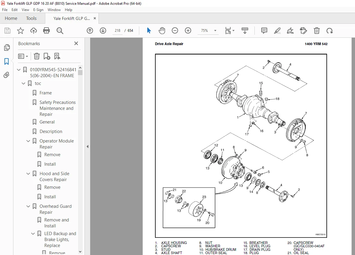
Drive Axle 213
Safety Precautions Maintenance and Repair 214
General 217
Description 217
Drive Axle Repair 217
Remove and Disassemble 217
Clean and Inspect 219
Assemble and Install 219
Torque Specifications 221
Troubleshooting 221
1600YRM532-524168419(10-2004)-EN STEERING AXLE 225
toc 225
Steering Axle 225
Safety Precautions Maintenance and Repair 226
General 229
Description 229
Steering Axle Assembly Repair 230
Remove 230
Install 230
Wheels and Hubs Repair 230
Pneumatic Tires, Remove and Disassemble 230
Cushion Tires, Remove and Disassemble 232
Pneumatic Tires, Assemble and Install 232
Cushion Tires, Assemble and Install 232
Spindles, Bearings, and Tie Rods Repair 233
Pneumatic Tires, Remove 233
Cushion Tires, Remove 233
Pneumatic Tires, Install 233
Cushion Tires, Install 234
Steering Cylinder Repair 234
Remove and Disassemble 234
Clean and Inspect 234
Assemble and Install 234
Torque Specifications 235
Troubleshooting 236
1600YRM720-524158753(07-2005)-UK-EN STEER CONTROL UNIT 239
toc 239
Steering Housing and Control Unit 239
Safety Precautions Maintenance and Repair 240
General 243
Description 243
Operation 244
Steering Wheel and Column Assembly Repair 245
Assembly Components, Remove 245
Steering Control Unit, Disassemble 250
Steering Control Unit, Clean 250
Steering Control Unit, Assemble 250
Assembly Components, Install 252
System Air Removal 254
Troubleshooting 254
1800YRM540-524168420(05-2002)-EN BRAKE SYSTEM 259
toc 259
Brake System 259
Safety Precautions Maintenance and Repair 260
General 263
Description and Operation 263
Service Brake 263
Parking Brake 264
Service Brakes Repair 264
Remove and Disassemble 264
Clean 267
Inspect 267
Assemble and Install 267
Adjust 270
Parking Brake Repair 271
Remove and Disassemble 271
Assemble and Install 272
Adjust 272
Master Cylinder Repair 272
Remove 272
Disassemble 272
Clean and Inspect 274
Assemble 274
Install 274
Service Brakes Adjustment 274
Brake System Air Removal 275
Parking Brake Not Applied Switch Test 275
Parking Brake Switch Test (Foot Directional Control Pedal Only) 275
Inching/Brake Pedal Adjustment 276
Torque Specifications 276
Troubleshooting 278
1900YRM539-524168421(05-2002)-EN HYDRAULIC SYSTEM 283
toc 283
Hydraulic System and Gear Pump Assembly 283
Safety Precautions Maintenance and Repair 284
General 287
Description and Operation 287
Hydraulic System 287
Gear Pump Assembly 289
Pump Drive Shaft 291
Steering Flow Divider 292
Relief Valve (Steering) 292
Relief Valve (Main Hydraulic) 293
Gear Pump Assembly Repair 294
Remove and Disassemble 294
Assemble and Install 294
Pump Drive Shaft Repair 294
Disassemble 294
Assemble and Install 295
Steering Relief Pressure Check and Adjust 295
Gear Pump Flow Check 295
Troubleshooting 296
2000YRM541-524168422(05-2002)-EN MAIN CONTROL VALVE 301
toc 301
Main Control Valve 301
Safety Precautions Maintenance and Repair 302
General 305
Description 305
Operation 306
Lift Section 307
Tilt Section 307
Tilt Backward 307
Tilt Forward 307
Steering Flow Divider 310
Relief Valve (Steering) 310
Relief Valve (Main Hydraulic) 310
Main Control Valve Repair 311
Remove 311
Disassemble 311
Clean and Inspect 311
Assemble 311
Install 311
Pressure Relief Valve Check and Adjustment 315
Steering Relief Valve 315
Main Hydraulic Relief Valve 316
Troubleshooting 316
2100YRM103-524150790(03-2005)-EN TILT CYLS 321
toc 321
Tilt Cylinders 321
Safety Precautions Maintenance and Repair 322
General 325
Description 325
Tilt Cylinder Repair 325
Remove 325
Disassemble 325
Clean 325
Assemble 325
Tilt Cylinders With O-Ring or Single-Lip Seals 325
Tilt Cylinders 326
Install 328
Tilt Cylinder Leak Check 330
Tilt Cylinder Stroke and Mast Tilt Angle Adjustment 331
Torque Specifications 331
Piston Rod Nut 331
Retainer 331
Troubleshooting 332
tables 321
Table 1 Movement Rates (Maximum) for Tilt Cylinders 330
2200YRM514-524158757(01-2004)-EN INSTRUMENT CLUSTER 337
toc 337
Instrument Cluster 337
Safety Precautions Maintenance and Repair 338
General 341
Description 341
Instrument Cluster Display Panel, Internal Combustion Lift Truck 341
Instrument Cluster Display Panel, Electric Lift Truck Models 348
Optional Basic Display Panel 348
Features of the Optional Basic Display Panel 348
Description of Features on the Optional Basic Display Panel 348
Standard Display Panel 349
Features of the Standard Display Panel 349
Description of Features on the Standard Display Panel 349
Premium Display Panel 350
Features on the Premium Display Panel 350
Description of Features on the Premium Display Panel 351
Curtis 1215 Display Panel 353
Description and Features 353
Operation 354
Cluster-Type Display Panel (Internal Combustion) Replacement 355
Remove 355
Install 355
Cluster Display Panel (Electric Lift Truck) Replacement 358
Curtis 1215 Display Panel Replacement 363
Remove 363
Install 363
tables 337
Table 1 Instrument Cluster, Internal Combustion 342
2200YRM524-524158758(12-2003)-EN ELECTRICAL SYSTEM LPG ENGINES 367
toc 367
Electrical System 367
Safety Precautions Maintenance and Repair 368
General 371
Description 371
Starting System 371
Ignition System 371
Charging System 372
Starter Repair 373
Remove and Disassemble 373
Assemble and Install 373
Coil Replacement 375
Distributor Repair 376
Remove and Disassemble 376
Assemble and Install 376
Distributor Repair 378
Remove and Disassemble 378
Assemble and Install 380
Alternator Repair 380
Remove and Disassemble 380
Assemble and Install 381
General Checks and Adjustments 382
Starter Checks 382
Operation, Check 382
Brush Holder, Check 383
Armature, Check 383
Field Windings, Check 383
Clutch and Bearing, Check 383
Ignition System Check and Adjustment 384
Engine Timing, Adjust 384
Spark Plugs, Check 384
Charging Circuit Checks 385
Low Output, Check 385
High Output, Check 386
Diodes, Check 386
Rotor Field Winding, Check 387
Stator Windings, Check 387
Brushes and Bearings, Check 387
Voltage Regulator, Check 387
Troubleshooting 388
2200YRM550-524168423(05-2002)-EN ELECTRICAL SYSTEM DIESEL ENGINES 393
toc 393
Electrical System 393
Safety Precautions Maintenance and Repair 394
General 397
Description 397
Starting Circuit 397
Charging System 398
Starter Repair 399
Remove and Disassemble 399
Assemble and Install 399
Alternator Repair 401
Remove and Disassemble 401
Assemble and Install 402
General Checks and Adjustments 403
Starter Checks 403
Operation Check 403
Solenoid Coil Checks 404
Brush Holder Check 404
Armature Check 404
Field Windings Check 404
Clutch and Bearing Check 404
Cold Start Aid Checks 405
Glow Plugs 405
Fuse 405
Relay and Controller 405
Charging Circuit Checks 406
Low-Output Check 406
High-Output Check 406
Diodes Check 407
Rotor Field Winding Check 408
Stator Windings Check 408
Brushes and Bearings 409
Voltage Regulator Check 409
Troubleshooting 409
4000YRM521-524158890(05-2004)-EN MAST 415
toc 415
Mast 415
Safety Precautions Maintenance and Repair 416
General 419
Description and Operation 419
Carriages 419
Mast Mounts 421
Two-Stage Mast, Limited Free-Lift (LFL) 422
Description and Operation 422
Two-Stage Mast, Full Free-Lift (FFL) 424
Description and Operation 424
Three-Stage Mast, Full Free-Lift (FFL) 426
Description and Operation 426
Cylinder Cushion During Lifting Sequence 429
Cylinder Cushion During Lowering Sequence 430
4000YRM522-524158891(05-2004)-EN MAST 433
toc 433
Mast 433
Safety Precautions Maintenance and Repair 434
General 437
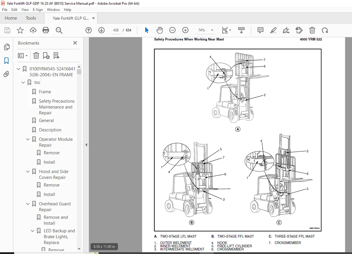
Safety Procedures When Working Near Mast 437
Forks Repair 439
Remove 439
Install 439
Carriages Repair 440
Standard Carriage, Remove 440
Hang-On Sideshift Carriage, Remove 441
Standard Carriage and Hang-On Sideshift Carriage, Repair 442
Standard Carriage, Install 442
Hang-On Sideshift Carriage, Install 443
Integral Sideshift Carriage 443
Remove 443
Clean and Inspect 445
Repair 445
Install 446
Mast Repair 446
Remove 446
Two-Stage LFL and Two-Stage FFL Masts, Disassemble 448
Three-Stage FFL Mast 455
Disassemble 455
Mast and Chains, Clean and Inspect 458
Two-Stage LFL and Two-Stage FFL Mast, Assemble 459
Three-Stage FFL Mast, Assemble 460
Install 461
Lift Cylinders Repair 463
Main Lift Cylinders, Remove 463
Free-Lift Cylinder, Remove 463
Lift Cylinders, Disassemble 464
Lift Cylinders, Assemble 465
Main Lift Cylinders, Install 467
Free-Lift Cylinder, Install 467
Header Hose Arrangements 468
Two-Stage LFL Mast, New Hose Install 468
Two-Stage LFL Mast, Adjust Hoses After Installation 473
Two-Stage FFL Mast, New Hose Install 473
Two-Stage FFL Mast, Adjust Hoses After Installation 478
Three-Stage FFL Mast, New Hose Install 478
Three-Stage FFL Mast, Adjust Hoses After Installation 490
Header Hose Arrangement 491
Two-Stage LFL Mast, New Hose Install 491
Two-Stage LFL Mast, Adjust Hoses After Installation 495
Two-Stage FFL Mast, New Hose Install 495
Two-Stage FFL Mast, Adjust Hoses After Installation 500
Three-Stage FFL Mast, New Hose Install 502
Three-Stage FFL Mast, Adjust Hoses After Install 510
Lift and Tilt System Leak Check 510
Lift Cylinders Leak Check 510
Tilt Cylinders Leak Check 510
Tilt Cylinders Adjustment 511
Lift Chains Adjustment 512
Mast Adjustment 514
Carriage Adjustment 516
Troubleshooting 516
tables 433
Table 1 Hook-Type Carriage Chain Adjustment 513
Table 2 Pin-Type Carriage Chain Adjustment 513
8000YRM231-524150797(12-2004)-UK-EN FASTENERS 521
toc 521
Metric and Inch (SAE) Fasteners 521
Safety Precautions Maintenance and Repair 522
General 525
Threaded Fasteners 525
Nomenclature, Threads 525
Strength Identification 526
Cotter (Split) Pins 526
Fastener Torque Tables 531
Conversion Table 533
tables 521
Table 1 Bolts and Screws 527
Table 2 Studs and Nuts 528
Table 3 Torque Nuts 529
Table 4 Torque Nuts with Nylon Insert 530
Table 5 Torque Values for Metric Fasteners* 531
Table 6 Torque Values for Inch Fasteners* 532
Table 7 Conversion Table for Metric and English Units 533
Table 8 Cotter Pin Dimensional Data 534
Table 9 Cotter Pin Dimensional Data 535
Table 10 Cotter Pin Dimensional Data 536
Table 11 Cotter Pin Dimensional Data 538
8000YRM544-524168426(06-2004)-EN DIAGRAMS 541
toc 541
Diagrams 541
Safety Precautions Maintenance and Repair 542
8000YRM546-524168425(05-2002)-EN CAPS & SPECS 577
toc 577
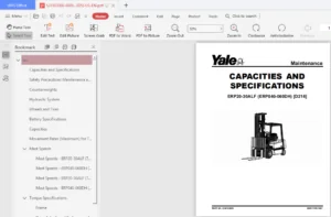
Capacities and Specifications 577
Safety Precautions Maintenance and Repair 578
Engine Specifications 581
Electrical System 581
Hydraulic System 582
Lift Truck Weights 582
Torque Converter Stall Speeds 583
Tire Pressure 583
Capacities 583
Mast Speeds 585
Mazda D5 Engine Mast Speeds 585
Mazda FE Engine Mast Speeds 585
Mazda XA Engine Mast Speeds 586
Transmission Oil Pressures 586
Torque Specifications 587
Brake System 587
Drive Axle 587
Engine – Mazda D5 587
Engine – Mazda FE 587
Engine – Mazda XA 588
Frame 589
Mast 589
Steering System 589
Transmission and Differential 589
8000YRM959-524175034(10-2004)-EN PERIODIC MAINTENANCE 593
toc 593
Periodic Maintenance 593
Safety Precautions Maintenance and Repair 594
General 599
Serial Number 599
How to Move Disabled Lift Truck 599
How to Tow Lift Truck 599
How to Put Lift Truck on Blocks 600
How to Raise Drive Tires 600
How to Raise Steering Tires 600
Maintenance Schedule 601
Maintenance Procedures Every 8 Hours or Daily 608
How to Make Checks With Engine Stopped 608
Tires and Wheels 608
Forks 609
Adjust 609
Remove 609
Install 609
Inspection of Forks, Mast, and Lift Chains 611
Safety Labels 612
Operator Restraint System 612
Steering Column Latch 612
Fuel, Oil, or Coolant Leaks Check 612
Drive Belts 613
Engine Oil Level 613
Brake Fluid 613
Hydraulic Oil Level 614
Transmission Oil 615
LPG Fuel Filters 615
Diesel Fuel Filter 615
How to Drain Water From Fuel Filter 615
Battery Electrolyte 615
How to Make Checks With Engine Running 616
Gauges, Indicator Lights, Horn, Fuses, and Relays 616
Control Levers and Pedals 617
Steering System 617
Service Brakes 617
Parking Brake 617
Cooling System 618
Lift System Operation 618
Maintenance Procedures Every 500 Hours or 3 Months 619
Engine Oil and Filter 619
Changing Engine Oil and Filter 619
Air Filter 619
Transmission Oil Level 620
Battery 620
Wheel Nuts 620
Engine Speed 620
LPG Engine 620
Diesel Engine 620
Lift Chains 621
Lubrication 621
Wear Check 621
Mast 621
Steering Axle 622
Spark Plugs, Mazda FE Engine 622
Differential 622
Drive Belts 622
Mazda FE LPG Engines 622
Mazda XA Diesel Engine 623
Inching/Brake Pedal 623
Forks 623
Diesel Fuel System 623
Replace Diesel Fuel Filter 623
Remove Air From Fuel System 624
Drain Tar From LPG Regulator 624
Steering Axle 624
Maintenance Procedures Every 1000 Hours or 6 Months 625
Pedals, Levers, Cables, and Other Linkages 625
Air Filter 625
LPG Fuel Filter 625
IMPCO Fuel Filter 625
Regulator Pressure/Diaphragm and O-Ring Checks 625
Spark Plugs 625
Ignition System, Mazda FE Engines 625
Injection Pump Timing, Mazda XA Diesel Engine 626
Valve Clearance Adjustment 627
Integral Sideshift Carriage, Check Bearings 627
Hydraulic Pump Drive Shaft 627
PCV Valve 628
Idle Circuit/Injector Filter Replace, Aisan Fuel System 628
Maintenance Procedures Every 2000 Hours or Yearly 628
Throttle Cable 628
Differential 628
Main Solenoid Valve (LPG Engine) 629
Hydraulic System 629
Replace Hydraulic Oil and Filter 629
Clean Hydraulic Tank Breather 629
Cooling System 629
Transmission 630
Replace Transmission Oil and Filter 630
Integral Sideshift Carriage, Replace Bearings 630
Gasoline Fuel Filter 630
LPG Fuel Filter 630
Aisan Fuel Filter 630
Hood Latch Check 631
Safety Procedures When Working Near Mast 632
Lift and Tilt System Leak Check 633
Lift Cylinders, Leak Check 633
Tilt Cylinders, Leak Check 635
Tilt Cylinder Adjustment 635
Lift Chain Adjustments 636
Service Brake Check 637
Diesel Engine Fuel Injector Check 638
Welding Repairs 638
Overhead Guard Changes 639
Wheel and Tire Replacement 639
General 639
Pneumatic Tire, Repair 639
Remove Wheels From Lift Truck 639
Remove Tire From Wheel 640
Remove Tire From Two-Piece Wheel 640
Remove Tire From Three- and Four-Piece Wheels 641
Install Wheel in Tire 642
Install Two-Piece Wheel in Tire 643
Install Three- or Four-Piece Wheel in Tire 644
Add Air to Pneumatic Tires 645
Wheels, Install 645
Solid Rubber Tires on Pneumatic Wheels, Change 645
Remove Tire From Wheel 646
Install Tire on Wheel 647
Operating Procedures for New or Rebuilt Engine 649
tables 593
Table 1 Maintenance Schedule 601
Table 2 Hook-Type Carriage Chain Adjustment 636
Table 3 Pin-Type Carriage Chain Adjustment 637
B810 Index 653
B810 653
S.V 07/24