Yale Forklift MSW 030-040 E (C820) Maintenance Manual – PDF DOWNLOAD
$29.95
Yale Forklift MSW 030-040 E (C820) Maintenance Manual – PDF DOWNLOAD
Description
Yale Forklift MSW 030-040 E (C820) Maintenance Manual – PDF DOWNLOAD
FILE DETAILS:
Yale Forklift MSW 030-040 E (C820) Maintenance Manual – PDF DOWNLOAD
Language : English
Pages : 440
Downloadable : Yes
File Type : PDF
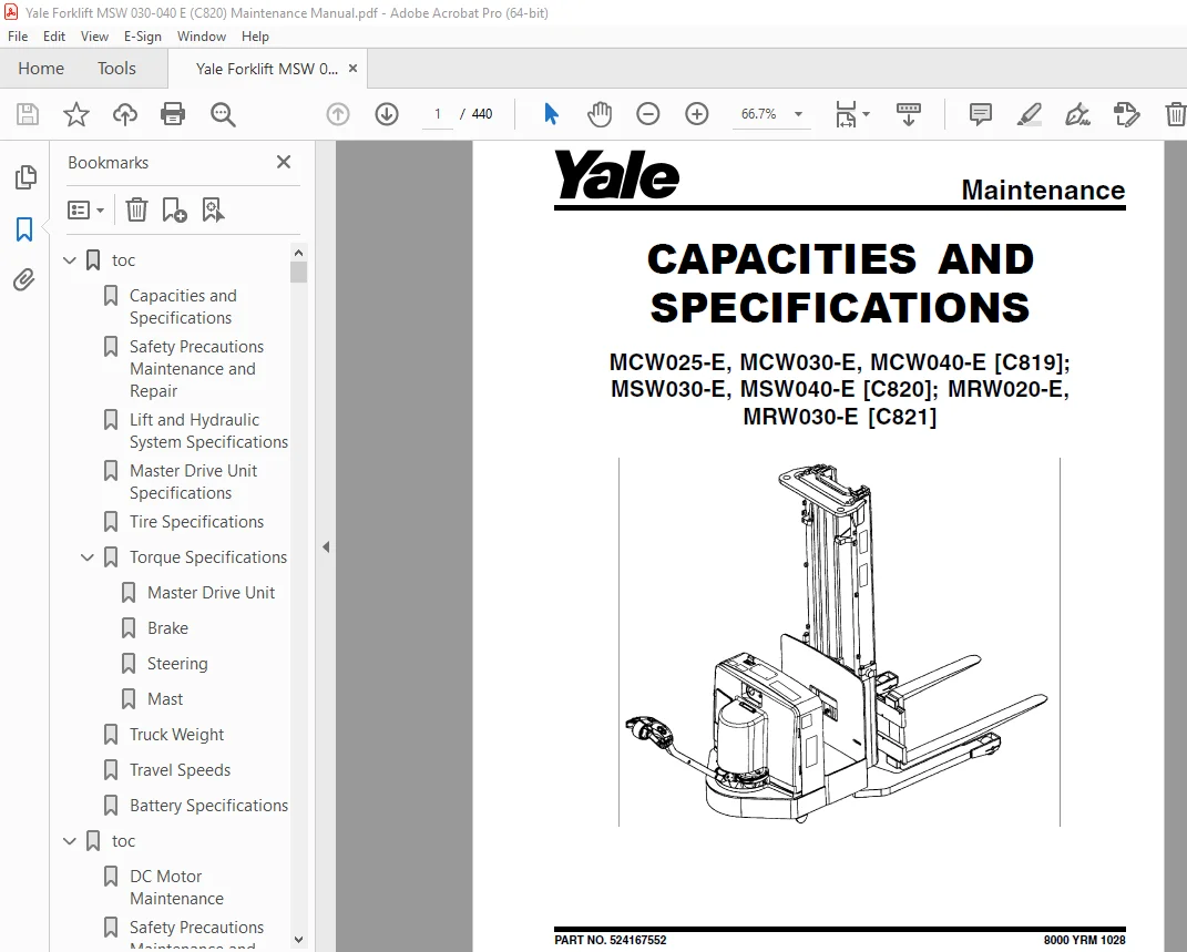
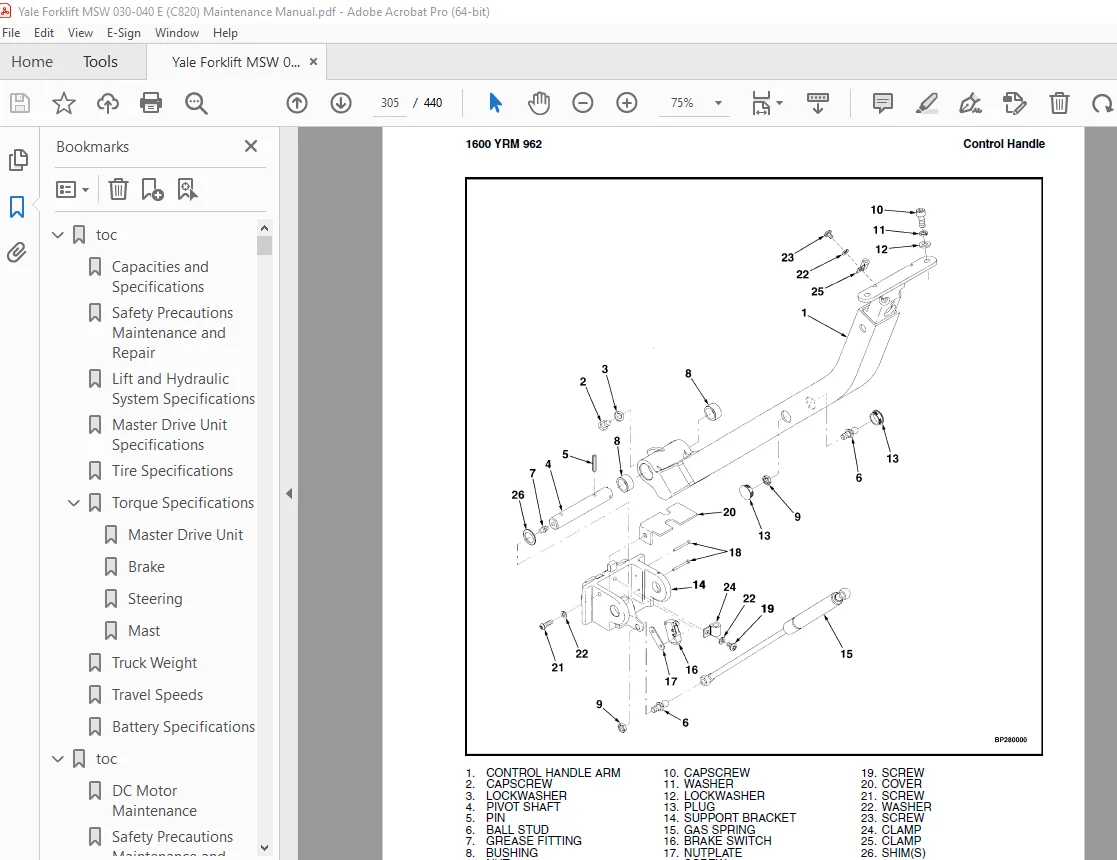
IMAGES PREVIEW OF THE MANUAL:
TABLE OF CONTENTS:
Yale Forklift MSW 030-040 E (C820) Maintenance Manual – PDF DOWNLOAD
toc 1
Capacities and Specifications 1
Safety Precautions Maintenance and Repair 2
Lift and Hydraulic System Specifications 5
Master Drive Unit Specifications 6
Tire Specifications 6
Torque Specifications 6
Master Drive Unit 6
Brake 6
Steering 6
Mast 6
Truck Weight 7
Travel Speeds 7
Battery Specifications 8
toc 11
DC Motor Maintenance 11
Safety Precautions Maintenance and Repair 12
General 15
Brush and Commutator Inspection 15
Hydraulic Pump Motor and Traction Motor 15
Steering Pump Motor 18
Normal Commutator Surface 18
Commutator Problems 18
Brush Replacement 22
Stoning the Commutator 24
Motors Repair 26
Disassemble 26
Traction Motor and Hydraulic Pump Motor 26
Steering Pump Motor 30
Assemble 30
Traction Motor and Hydraulic Pump Motor 30
Steering Pump Motor 31
Brush Alignment, Traction and Hydraulic Motors 34
Tests for Damaged Field and Armature 34
Test for an Open Circuit in Armature 34
Test for Short Circuit in One Armature Winding 35
Test for Short Circuit to Armature Shaft 35
Test for Open Circuit in Field Coil 35
Test for Short Circuit in Field Coil 35
Test for Short Circuit between Field and Motor Case 36
Brush Holder Test 36
Troubleshooting 36
tables 11
Table 1 Normal Commutator Surfaces 17
Table 2 Commutator Problems 18
Table 3 Brush Wear Replacement Guide 22
toc 41
Diagrams 41
Safety Precautions Maintenance and Repair 42
toc 85
Electrical System 85
Safety Precautions Maintenance and Repair 86
General 89
Description of Operation 90
Special Precautions 92
Moving a Disabled Lift Truck 93
Electrical System Checks 93
Safety Precautions 93
Repairs 95
Controller, Replace 95
Remove 95
Install 95
Contactor Coil, Check 97
Contactor, Replace 97
Remove 97
Install 97
Key Switch Removal and Installation 97
Remove 97
Install 98
Battery Indicator/Hourmeter Display 98
Remove 98
Install 98
Fuses 98
Brake Switch 99
Description 99
Remove 99
Install 100
Control Handle 100
Disassemble 100
Calibrate New Control Handle Card 103
Assemble 103
Drive Motor 104
Remove 104
Install 104
Disassemble 104
Assemble 105
Lift Pump Motor 106
Remove 106
Install 106
Troubleshooting 108
General Troubleshooting 108
Hydraulic Troubleshooting 109
tables 85
Table 1 Side-Shift – Aux Board Output 113
Table 2 Side-Shift – Motor Controller Outputs 113
Table 3 Side-Shift – Aux Board Inputs 113
Table 4 Tilt – Aux Board Output 116
Table 5 Tilt – Motor Controller Outputs 116
Table 6 Tilt – Aux Board Inputs 116
Table 7 Tilt – Controller Inputs (Handset or PC Tester Menu) 117
Table 8 Reach – Aux Board Output 119
Table 9 Reach – Motor Controller Outputs 119
Table 10 Reach – Aux Board Inputs 119
Table 11 Reach – Controller Inputs (Handset or PC Tester Menu) 119
toc 125
Frame 125
Safety Precautions Maintenance and Repair 126
General 129
Features (MSW030/040-E and MRW020/030-E) 129
Features (MCW025/030/040-E) 129
Frame Repair 132
Painting Instructions 132
Label Replacement 132
Battery Compartment 135
Battery Roller Option 135
Remove 135
Install 135
toc 139
Industrial Battery 139
Safety Precautions Maintenance and Repair 140
General 143
Lead-Acid Batteries 143
Specific Gravity 144
Chemical Reaction in a Cell 144
Electrical Terms 145
Battery Selection 146
Battery Voltage 147
Battery as a Counterweight 147
Battery Ratings 147
Kilowatt-Hours 147
Battery Maintenance 148
Safety Procedures 148
Maintenance Records 148
New Battery 148
Cleaning Battery 149
Adding Water to Battery 150
Hydrometer 150
Battery Temperature 151
Charging Battery 152
Types of Battery Charges 153
Methods of Charging 154
Troubleshooting Charger 154
Knowing When Battery Is Fully Charged 155
Where to Charge Batteries 155
Equipment Needed 155
Battery Connectors 155
Battery Care 156
tables 139
Table 1 Battery Capacity Terms 147
toc 161
Lift Cylinders 161
Safety Precautions Maintenance and Repair 162
General 165
Description 165
Lowering Control Valve 166
Main Cylinder Repair 167
Disassemble 167
Assemble 168
Free-Lift Cylinder Repair 170
Disassemble 170
Assemble 170
Troubleshooting 171
toc 175
Mast 175
Safety Precautions Maintenance and Repair 176
General 179
Mast Weldments 179
Carriages 181
Two-Stage Mast 184
Description 184
Operation 189
Three-Stage Mast 189
Description 189
Operation 192
toc 197
Mast 197
Safety Precautions Maintenance and Repair 198
General 201
Safety Procedures When Working Near Mast 201
Load Backrest Extension, Carriage, Load Rollers, Side Rollers, a 203
Load Backrest Extension, Remove and Install 203
Carriage Assembly, Remove and Install 203
Carriage Load Rollers, Remove and Install 205
Side Rollers, Disassemble and Assemble 206
Fork, Replace 206
Forks – Hook Type 206
Remove 206
Install 208
Two-Stage Mast Assembly 208
Remove 208
Clean and Inspect 211
Lift Cylinders, Remove and Install Dual-Lift Cylinders 213
Lift Cylinder, Remove and Install Single-Lift Cylinders 214
Remove 214
Install 215
Inner Mast Assembly, Remove and Install 216
Hoses, Replace 216
Hose and Cable Sheaves, Replace 216
Two-Stage Lift Chains 218
Remove and Install 218
Clean and Inspect 218
Two-Stage Chain Sheave, Remove and Install 218
Load Rollers and Wear Plugs, Remove and Install 219
Two-Stage Mast Assembly, Install 220
Three-Stage Mast Assembly 221
Three-Stage Mast Assembly, Remove 221
Clean and Inspect 224
Free-Lift Cylinder, Remove and Install 224
Main Cylinders (Standard), Remove and Install 225
Inner and Intermediate Mast Assemblies, Remove and Install 227
Hoses, Replace 227
Hose and Cable Sheaves, Replace 227
Free-Lift Hose Sheave 229
Carriage Sheaves 229
Three-Stage Lift Chains, Remove and Install 230
General 230
Free-Lift Chains 230
Main-Lift Chains 230
Three-Stage Chain Sheaves, Disassemble and Assemble 230
Free-Lift Chain Sheaves 230
Main-Lift Chain Sheaves 231
Load Rollers and Wear Plugs, Remove and Install 231
Three-Stage Mast Assemble, Install 232
Mast Operation Check 233
Hydraulic System Leaks Check 233
Lift Chains Check 234
General 234
Clean and Inspect 234
Lubrication 234
Mast Adjustments 236
General 236
Adjust Wear Plugs – Mast 236
Adjust Free-Lift Chain (Three-Stage Only) 237
Adjust Main-Lift Chains 238
Two-Stage 238
Three-Stage 239
Adjust Wear Strips 239
Carriage Adjustments 240
Adjust Wear Plug – Carriage 240
Adjust Side Rollers – Carriage 240
Adjust Thrust Rollers – Carriage 241
Troubleshooting 242
toc 245
Master Drive Unit 245
Safety Precautions Maintenance and Repair 246
General 249
Check Oil Level 249
Safety Precautions 250
Drive Tire 251
Remove 251
Install 251
Master Drive Unit 252
Remove 252
Install 255
Troubleshooting 256
tables 245
Table 1 Drive Unit Specifications 249
toc 259
Periodic Maintenance 259
Safety Precautions Maintenance and Repair 260
General 263
How to Move a Disabled Lift Truck 263
How to Tow Lift Truck 263
How to Put The Lift Truck on Blocks 265
How to Raise Drive/Steer Tire 265
How to Raise the Load Wheels (MSW030/040-E and MRW020/030-E) 266
How to Raise The Load Wheels (MCW025/030/040-E) 266
Maintenance Schedule 267
Safety Procedures When Working Near Mast 272
Maintenance Procedures Every 8 Hours or Daily 274
Checks Before Operation 274
How to Make Checks With Key Switch OFF 274
Safety Labels 274
Battery 275
Brake 275
Tires and Wheels 275
Mast, Forks, and Lift Chains 276
Reach Mechanism (MRW020/030-E) 278
Control Handle 278
Hydraulic System 278
How to Make Checks With Key Switch ON 278
Check for Leaks in Lift System 278
Control Buttons 279
Direction/Speed Control and Switches 279
Gauges, Horn, Fuses 279
Maintenance Procedures Every 350 Hours or Every 2 Months 280
Fittings Lubrication 280
Lift Chain Adjustments 281
Drive Wheel 282
Brake 283
Hydraulic System 283
Fluid Level 283
Hydraulic Reservoir Breather 283
Master Drive Unit 283
Check Oil Level 283
Traction and Pump Motor Brushes 284
Contactor 285
Maintenance Procedures Every 2000 Hours or Yearly 286
Hydraulic Oil Change 286
Load Wheel Bearings ( MCW025/030/040-E ) 287
Remove 287
Install 289
Master Drive Unit 289
Drive Unit Gear Oil 289
Welding Repairs 289
General Repairs 290
Load Wheels ( MSW030/040-E and MRW020/030-E ) 290
Remove 290
Install 290
Battery Maintenance 292
How to Charge Battery 292
Normal Charge 292
Equalizing Charge 293
How to Change Battery 293
Standard Battery Spacer Adjustment 293
Changing Battery With Overhead Crane 294
Remove 294
Install 294
Changing Battery With Rollers 295
Remove 295
Install 296
tables 259
Table 1 Maintenance Schedule 270
Table 2 Fuse Ratings 280
Table 3 Hydraulic Reservoir Capacity 287
toc 299
Steering Mechanism 299
Safety Precautions Maintenance and Repair 300
General 303
Special Precautions 303
Control Handle Head 304
Control Handle 304
MPW060/065/080-E, MSW030/040-E, MRW020/030-E, and MCW025/030/040 304
Remove 304
Install 306
Control Handle 307
MPE060/080-E 307
Remove (Handle) 307
Steer Bearings and Support 309
Disassemble 309
Repair 309
Assemble 309
Install (Handle) 310
Steering and Dash Assembly (Complete) 311
Remove 311
Install 311
Troubleshooting 313
toc 317
Walkie High Lift Hydraulic System 317
Safety Precautions Maintenance and Repair 318
General 321
Description of Operation 321
Hydraulic Oil 322
Clean 322
Sound Level 322
Special Precautions 322
Control Valve 323
Hydraulic Reservoir 324
Description 324
Manual Lowering 324
Lift Pump and Motor Repair 326
General 326
Remove Lift Pump and Motor Assembly 326
Disassemble 332
Remove Reservoir 332
Remove Pump Motor 332
Disassemble Pump 332
Assemble 333
Assemble Pump 333
Install Pump Motor 333
Install Reservoir to Pump 333
Install Lift Pump and Motor Assembly 333
Valve Repair 334
Proportional Valve (Lowering) 334
Remove 334
Install 334
Directional Valve 335
Remove 335
Install 335
Lift Valve 336
Remove 336
Install 336
Counterbalance Valve 336
MRW020/030-E 336
Remove 336
Install 337
MCW025/030/040-E 338
Remove 338
Install 338
Relief Valve and Check Valve 338
Remove 339
Install 339
Pilot Operated Check Valve 339
MRW020/030-E 339
Remove 339
Install 340
Selector Valves: Reach, Tilt, and Sideshift 340
MRW020/030-E and MCW025/030/040-E 340
Remove 340
Install 341
Relief Valve Adjustment 342
Bleed Hydraulic System 343
Troubleshooting 343
Hydraulic Diagrams and Schematics 345
tables 317
Table 1 Hydraulic Reservoir 324
toc 365
ZAPI™ Controllers 365
Safety Precautions Maintenance and Repair 366
General 369
Description 369
ZAPI™ Transistor Motor Controller 369
Principles of Operation 370
Controller Safety 370
Controller Adjustments 371
Modes of Operation 371
User-Selectable Operating Modes 371
Programming 372
Custom Performance Mode 372
Controller Parameters 372
Tester Menu 373
Set Option Menu 373
ZAPI™ Handset 374
Troubleshooting 378
ZAPI™ PC Interface 396
Connecting PC to ZAPI™ Controller 396
File Menu 399
Open File 399
TX From File 400
Save File 402
Print Settings 404
Exit 405
Connection Menu 406
Function Menu 406
Parameter 406
Memory Menu 411
Set Options 412
Tester 414
Data Logger 416
Alarm Logbook 418
Alarms 419
Repair 419
Remove 419
Install 420
Repair 420
tables 365
Table 1 Parameters 372
toc 423
Brakes 423
Safety Precautions Maintenance and Repair 424
General 427
Description 427
Special Precautions 429
Brake Assembly Repair 431
MPW060-E and MPE060-E (⇒10/2001) 431
Remove 431
Install 432
MPW060-E and MPE060-E (10/2001⇒), MPE080-E, MTR005-E, MTR007-E 432
Remove 432
Install 433
Brake Assembly Adjustment 435
Air Gap, Adjust 435
Torque Nut, Adjust 436
Adjust 437
MPW060-E, MPW080-E, and MPE060-E Equipped With Brake Assembly Pa 437
MPW060-E, MPW080-E, MPE060-E, and All Other Models Covered by Th 437
Troubleshooting 438
tables 423
Table 1 Adjustment Specifications 436
S.V 07/24