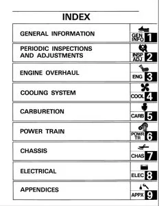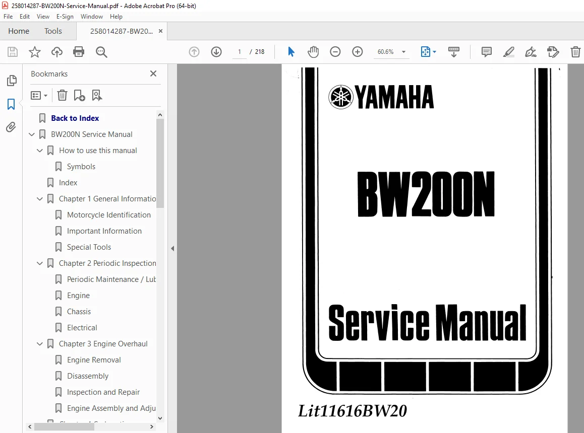
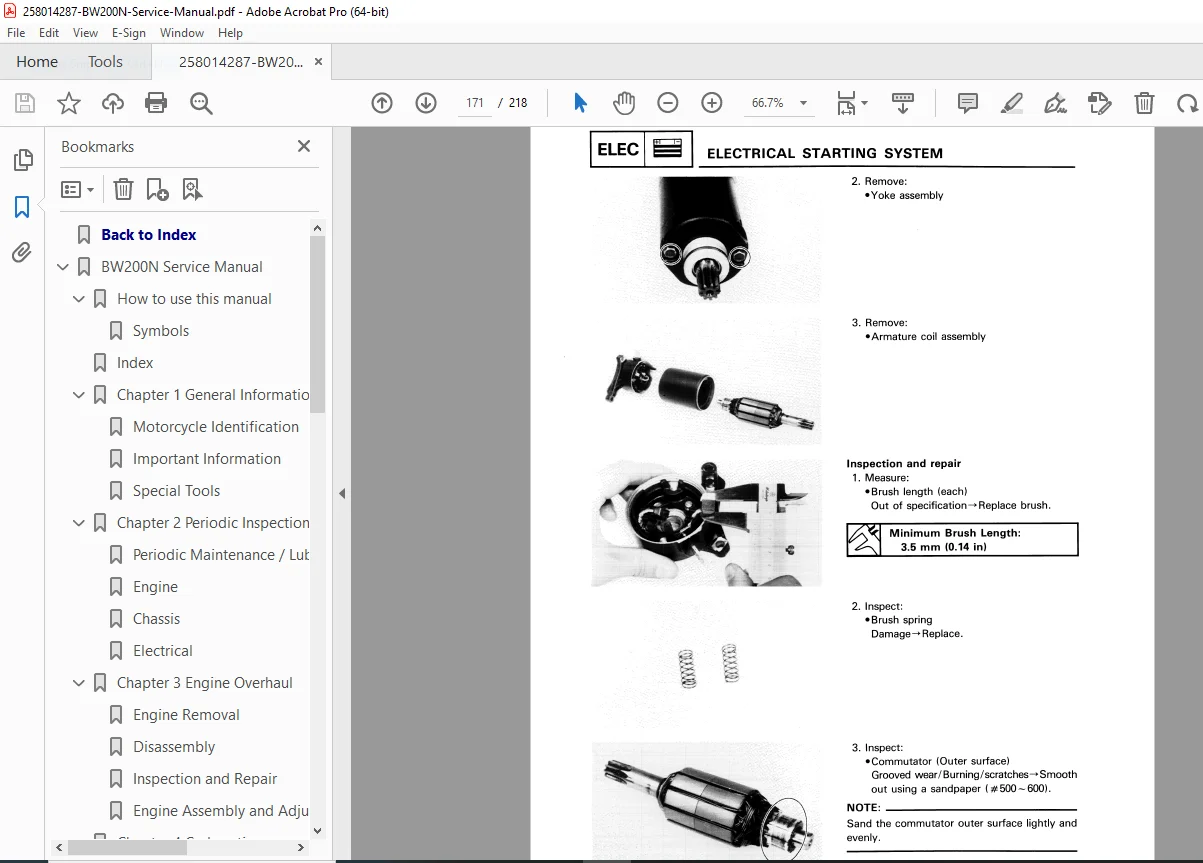
Yamaha BW200N Service Manual PDF (Big Wheel Repair/Engine/Wiring ’85)
Original price was: $70.00.$28.95Current price is: $28.95.
Got an electric start Yamaha BW200N Big Wheel? This is the official Yamaha Service Manual (LIT-11616-BW-1N) PDF download you need for repairs and service. Forget guesswork, this is the factory guide. Covers complete teardown, BW200N engine overhaul procedures, carb tuning, electrical system checks including the 1985 Yamaha BW200 wiring diagram, chassis, and everything else. Essential for keeping that classic Big Wheel running right.
Description
Yamaha BW200N Service Manual – PDF DOWNLOAD (Big Wheel Repair/Engine/Wiring ’85)
IMAGES:
Product Description
Main Product Title:
Yamaha BW200N Service Manual PDF – Official 1985 Big Wheel 200 Electric Start Factory Manual (LIT-11616-BW-1N)
Full Product Description:
The Official Factory Manual for Your Yamaha Big Wheel 200N
Keeping one of the original Yamaha Big Wheel 200s alive – especially the BW200N electric start model? That’s awesome! Finding accurate factory information for these classic machines can be challenging. This is the Official Yamaha BW200N Service Manual (LIT-11616-BW-1N) – the exact same PDF that Yamaha dealers used back in 1985. Whether you’re tackling basic maintenance or a complete rebuild, this is your authoritative guide.
The Electric Start Big Wheel – Factory Documentation
The BW200N represents the electric start variant of Yamaha’s iconic Big Wheel series. This manual is specifically tailored to the N model’s unique features including the electric starter system, battery, and related electrical components that differ from the kick-start-only versions.
Complete Technical Coverage
This manual is packed with detailed technical information covering every system:
- Complete BW200N engine overhaul procedures (top to bottom rebuild)
- Transmission and clutch service (complete disassembly/assembly)
- Fuel system (Yamaha BW200 carburetor adjustment and complete rebuild)
- Electrical system (starter motor, charging system, ignition, CDI)
- Complete 1985 Yamaha BW200 wiring diagram (fold-out schematic)
- Chassis and suspension (front fork, rear shock, swing arm)
- Brake systems (front and rear drum brakes)
- Those iconic big wheels (service and tire installation)
You’ll get detailed exploded diagrams, step-by-step instructions, factory specifications, wear tolerances, and comprehensive troubleshooting charts. This is the definitive Yamaha Big Wheel 200 repair guide for the electric start N model.
🔧 Complete Manual Contents
Official Factory Service Manual (254 Pages)
Chapter 1: General Information
- Machine Identification
- VIN (Vehicle Identification Number) location
- VIN decoding
- Engine serial number location
- Model year identification
- Production date information
- Features
- BW200N model overview
- Electric start system highlights
- Big wheel design advantages
- Model-specific features
- Technical innovations
- Complete Specifications
- General Specifications:
- Dimensions (length, width, height)
- Wheelbase
- Ground clearance
- Seat height
- Dry weight
- Fuel capacity
- Oil capacity
- Maintenance Specifications:
- Service intervals
- Fluid capacities
- Recommended lubricants
- Filter specifications
- Engine Specifications:
- Engine type (air-cooled 2-stroke single)
- Displacement (192cc)
- Bore and stroke
- Compression ratio
- Carburetor specifications
- Ignition system type
- Starting system (electric & kick)
- Lubrication system (oil injection)
- Chassis Specifications:
- Frame type
- Front fork type and travel
- Rear suspension type and travel
- Tire sizes (front/rear big wheels)
- Brake types
- Drive chain specifications
- Electrical Specifications:
- Battery specifications
- Charging system output
- Headlight/taillight specifications
- Fuse ratings
- Bulb specifications
- General Specifications:
- Cable Routing Diagram
- Throttle cable routing
- Clutch cable routing
- Brake cable routing
- Choke cable routing
- Oil injection cable routing
- Proper cable routing to prevent binding
- Special Tools
- Complete special tools list
- Tool part numbers
- Tool descriptions and applications
- Alternative tool suggestions where applicable
Chapter 2: Periodic Inspection and Adjustment
- Introduction
- Importance of periodic maintenance
- Service record keeping
- Safety precautions
- Maintenance Interval Chart
- Time-based intervals (months)
- Mileage-based intervals
- Task checklist by interval
- Initial service requirements
- Regular service requirements
- Engine Maintenance
- Tune-Up Procedures:
- Inspection points
- Performance checks
- Adjustment procedures
- Valve Clearance Adjustment:
- Checking procedure
- Clearance specifications
- Adjustment method
- Idle Speed Adjustment:
- Warm-up requirements
- Adjustment procedure
- Idle speed specification
- Spark Plug Service:
- Plug removal and inspection
- Reading plug condition
- Gap specification
- Recommended plug type
- Torque specification
- Compression Test:
- Testing procedure
- Compression specification
- Low compression diagnosis
- Air Cleaner Service:
- Element removal
- Cleaning procedures
- Oil application (foam element)
- Installation
- Exhaust System:
- Inspection for leaks
- Carbon buildup removal
- Silencer service
- Tune-Up Procedures:
- Chassis Maintenance
- Brake Service:
- Brake shoe inspection
- Adjustment procedures
- Cable lubrication
- Drum inspection
- Clutch Adjustment:
- Cable free play check
- Adjustment procedure
- Cable lubrication
- Drive Chain Service:
- Slack adjustment procedure
- Lubrication schedule
- Wear inspection
- Alignment check
- Wheels and Tires:
- Tire pressure specifications
- Tread depth inspection
- Wheel bearing check
- Rim inspection
- Spoke tension (if applicable)
- Steering System:
- Handlebar play check
- Steering head bearing adjustment
- Cable inspection
- Suspension:
- Front fork oil level check
- Shock absorber inspection
- Swing arm bearing play check
- Fasteners:
- Critical fastener torque check
- Hardware inspection
- Brake Service:
- Electrical System Maintenance
- Battery Service:
- Electrolyte level check
- Charging procedures
- Terminal cleaning
- Load testing
- Fuse Inspection:
- Fuse locations
- Checking procedures
- Replacement specifications
- Lights and Switches:
- Operation checks
- Bulb inspection
- Switch testing
- Lens cleaning
- Battery Service:
- Lubrication
- Complete lubrication schedule
- Lubrication point diagram
- Recommended lubricants
- Cable lubrication
- Control pivot lubrication
- Bearing lubrication
Chapter 3: Engine Overhaul
- Engine Removal
- Preparation and safety
- Drain procedures (oil, coolant if applicable, fuel)
- Cable and hose disconnection
- Exhaust system removal
- Carburetor removal
- Engine mounting bolt removal
- Engine extraction from frame
- Installation notes
- Engine Disassembly
- External Components:
- Side covers removal
- Clutch cover removal
- Magneto/stator cover removal
- Cylinder head cover removal
- Cylinder Head:
- Bolt removal sequence
- Head removal
- Gasket removal
- Valve inspection access
- Cylinder and Piston:
- Cylinder removal
- Piston pin removal
- Piston ring removal
- Piston removal from connecting rod
- Clutch Assembly:
- Pressure plate removal
- Friction and steel plate removal
- Clutch basket removal
- Primary drive gear removal
- Oil Pump:
- Oil pump removal
- Drive gear removal
- Disassembly procedures
- Kickstarter Mechanism:
- Kickstarter shaft removal
- Spring and pawl inspection
- Gear inspection
- Crankcase Splitting:
- Crankcase bolt removal sequence
- Case separation procedure
- Special considerations
- Transmission:
- Shift drum removal
- Shift fork removal
- Main shaft removal
- Counter shaft removal
- Gear inspection
- Crankshaft:
- Crankshaft removal from cases
- Connecting rod inspection
- Crankpin bearing access
- Balancer System:
- Balancer shaft removal
- Gear inspection
- Timing verification
- External Components:
- Inspection and Repair
- Cylinder Head:
- Warpage measurement
- Valve seat inspection
- Valve guide wear measurement
- Combustion chamber inspection
- Valves and Springs:
- Valve stem measurement
- Valve face inspection
- Spring free length measurement
- Spring tension testing
- Cylinder:
- Bore measurement (multiple points)
- Out-of-round measurement
- Taper measurement
- Wear limits
- Honing requirements
- Piston and Rings:
- Piston diameter measurement
- Piston-to-cylinder clearance
- Ring end gap measurement
- Ring groove wear inspection
- Piston pin bore inspection
- Crankshaft:
- Runout measurement
- Connecting rod side clearance
- Big end bearing play
- Small end bearing inspection
- Crankshaft straightness
- Transmission Components:
- Gear tooth inspection
- Dog engagement surface inspection
- Shaft straightness check
- Bearing inspection
- Shift fork wear measurement
- Clutch Components:
- Friction plate thickness measurement
- Steel plate warpage check
- Spring free length measurement
- Basket groove wear inspection
- Hub spline inspection
- Oil Pump:
- Pump rotor clearance
- Body wear inspection
- Drive gear wear
- Crankcase:
- Bearing bore inspection
- Seal seat inspection
- Mating surface condition
- Stud and thread inspection
- Cylinder Head:
- Engine Assembly and Adjustment
- Assembly Preparation:
- Parts cleaning procedures
- Gasket and seal replacement
- Bearing installation
- Lubrication requirements
- Crankshaft Installation:
- Bearing installation
- Crankshaft positioning in case
- End play verification
- Transmission Assembly:
- Gear installation sequence
- Shift fork installation
- Shift drum installation
- Operation verification
- Crankcase Joining:
- Sealant application
- Case alignment
- Bolt tightening sequence
- Torque specifications
- Rotation check
- Balancer Installation:
- Timing mark alignment
- Gear mesh verification
- Kickstarter Assembly:
- Spring installation
- Shaft installation
- Operation check
- Oil Pump Installation:
- Drive gear installation
- Pump installation
- Priming procedure
- Clutch Assembly:
- Primary drive installation
- Clutch basket installation
- Plate installation sequence
- Spring installation
- Adjustment
- Piston and Cylinder:
- Piston ring installation (gap positioning)
- Piston installation on rod
- Cylinder installation
- Base gasket selection
- Cylinder Head:
- Gasket installation
- Head installation
- Bolt tightening sequence
- Torque specifications
- Valve adjustment
- External Components:
- Cover installation with new gaskets
- Oil injection pump installation
- Carburetor installation
- Engine Installation:
- Engine positioning in frame
- Mounting bolt installation and torque
- Reconnection of all cables/hoses
- Fluid filling
- Break-in procedures
- Assembly Preparation:
Chapter 4: Carburetion
- Carburetor System Overview
- Carburetor type (Mikuni VM series)
- Function explanation
- Circuit descriptions (pilot, main, starting)
- Carburetor Diagram & Function
- Exploded view diagram
- Component identification
- Fuel flow path
- Air flow path
- Removal
- Airbox removal
- Cable disconnection
- Fuel line disconnection
- Carburetor removal from manifold
- Disassembly
- Float bowl removal
- Jet removal (main jet, pilot jet)
- Needle and slide removal
- Float and needle valve removal
- Complete component separation
- Cleaning
- Carburetor cleaner usage
- Passage cleaning (no wire in jets)
- Compressed air drying
- O-ring and seal inspection
- Inspection
- Body for cracks or damage
- Slide wear inspection
- Needle wear inspection
- Jet orifice inspection
- Float condition
- Needle valve and seat inspection
- Spring testing
- Assembly
- Component installation sequence
- O-ring lubrication
- Proper jet installation
- Float installation
- Slide and needle installation
- Installation
- Carburetor mounting
- Cable connection and adjustment
- Fuel line connection
- Airbox installation
- Adjustments
- Float Height Adjustment:
- Measurement procedure
- Specification
- Tang bending adjustment
- Idle Speed Adjustment:
- Warm-up requirements
- Idle speed screw adjustment
- Target idle RPM
- Pilot Screw Adjustment:
- Initial setting
- Fine-tuning procedure
- Optimal performance setting
- Float Height Adjustment:
- Fuel Tank Service
- Tank removal
- Cleaning procedures
- Petcock operation check
- Petcock disassembly/cleaning
- Filter screen cleaning
- Tank installation
Chapter 5: Chassis
- Wheels
- Front Wheel:
- Removal procedure
- Installation procedure
- Axle torque specification
- Rear Wheel:
- Chain adjustment release
- Removal procedure
- Installation procedure
- Axle torque specification
- Chain adjustment after installation
- Wheel Inspection:
- Rim runout measurement (radial/lateral)
- Rim damage inspection
- Hub inspection
- Bearing and Seal Service:
- Bearing removal
- Bearing inspection (roughness, play)
- Seal removal
- New bearing installation
- Seal installation
- Bearing lubrication
- Tire Service:
- Tire removal (big wheel considerations)
- Bead breaking
- Tire inspection
- Tube inspection
- Tire installation
- Balancing (if required)
- Pressure specifications
- Front Wheel:
- Brakes
- Front Drum Brake:
- Cable adjustment
- Brake panel removal
- Shoe inspection and measurement
- Drum inspection and measurement
- Cam and spring inspection
- Reassembly and adjustment
- Rear Drum Brake:
- Rod/cable adjustment
- Inspection procedures
- Shoe replacement
- Drum service
- Reassembly
- Front Drum Brake:
- Drive Chain and Sprockets
- Chain Adjustment:
- Slack measurement
- Adjustment procedure
- Specification
- Chain Inspection:
- Wear measurement (20-link method)
- Kinked link detection
- Lubrication requirements
- Chain Replacement:
- Master link removal
- Chain removal
- New chain installation
- Master link installation and orientation
- Sprocket Inspection:
- Tooth wear inspection
- Front sprocket removal/installation
- Rear sprocket removal/installation
- Sprocket replacement criteria
- Chain Adjustment:
- Steering System
- Handlebar:
- Removal procedures
- Control installation
- Alignment
- Installation torque
- Steering Head:
- Play check procedure
- Bearing adjustment procedure
- Bearing removal
- Bearing race removal/installation
- Bearing lubrication
- Preload adjustment
- Stem nut torque
- Handlebar:
- Front Fork
- Fork Removal:
- Front wheel removal
- Fender removal
- Brake panel disconnection
- Fork leg removal
- Fork Disassembly:
- Fork cap removal
- Spring removal
- Damper rod removal
- Fork tube separation
- Fork Inspection:
- Tube straightness check
- Chrome surface inspection
- Bushing wear inspection
- Spring free length measurement
- Oil seal inspection
- Fork Assembly:
- New seal installation
- Damper rod installation
- Spring installation
- Fork oil specification and quantity
- Air bleed procedure
- Cap installation and torque
- Fork Installation:
- Fork tube installation in triple clamps
- Alignment procedure
- Torque specifications
- Brake and fender installation
- Fork Removal:
- Rear Suspension
- Shock Absorber:
- Removal procedures
- Inspection (leaks, damage, damping)
- Installation
- Preload adjustment
- Swing Arm:
- Removal procedure
- Bushing inspection
- Bushing replacement
- Dust seal replacement
- Lubrication
- Installation
- Pivot bolt torque
- Play adjustment
- Shock Absorber:
Chapter 6: Electrical
- Electrical System Overview
- Complete electrical components diagram
- System description
- Safety precautions
- Checking Switches and Connections
- Visual inspection procedures
- Continuity testing
- Switch operation verification
- Connector cleaning
- Battery Service
- Battery location and removal
- Electrolyte level check and filling
- Charging procedures
- Specific gravity testing
- Load testing
- Terminal cleaning
- Installation
- Charging System
- System Description:
- Alternator/stator operation
- Regulator/rectifier function
- Alternator Output Check:
- Test procedure
- AC voltage specification
- No-load and load test
- Regulator/Rectifier Check:
- Voltage regulation test
- Rectifier diode testing
- Replacement procedures
- System Description:
- Ignition System (CDI)
- System Description:
- CDI (Capacitor Discharge Ignition) operation
- Pickup coil function
- Ignition coil function
- CDI Unit Check:
- Testing limitations (replacement test often required)
- Output signal check (if possible)
- Ignition Coil Checks:
- Primary winding resistance
- Secondary winding resistance
- Spark plug cap resistance
- Specifications
- Pickup Coil Check:
- Resistance measurement
- Signal output check
- Air gap inspection
- Ignition Timing:
- Timing mark location
- Timing specification
- Static timing procedure
- Strobe timing procedure (if applicable)
- System Description:
- Electric Starter System
- System Components:
- Starter motor
- Starter relay
- Start button
- Safety switches (clutch, neutral)
- Starter Motor Service:
- Removal procedures
- Disassembly
- Brush inspection and measurement
- Commutator inspection and service
- Armature testing
- Field coil testing
- Reassembly
- Installation
- Starter Relay Check:
- Relay operation test
- Coil resistance check
- Contact continuity check
- Switch Checks:
- Start button continuity
- Clutch switch operation
- Neutral switch operation
- Kill switch operation
- System Components:
- Lighting System
- Headlight:
- Bulb replacement
- Aim adjustment
- Switch testing
- Hi/Lo beam operation
- Taillight/Brake Light:
- Bulb replacement
- Brake light switch adjustment
- Switch testing
- Indicator Lights:
- Neutral indicator
- High beam indicator
- Turn signal indicators
- Bulb replacement
- Headlight:
- Signal System
- Turn Signals:
- Bulb replacement
- Switch testing
- Flasher relay check
- Flash rate troubleshooting
- Horn:
- Operation check
- Adjustment (if applicable)
- Replacement
- Turn Signals:
- Wiring Diagram
- Complete color-coded wiring schematic
- Component location reference
- Connector identification
- Wire color codes
- Ground point locations
- Fuse and relay locations
- Circuit tracing guide
Chapter 7: Troubleshooting
- Starting Failure / Hard Starting
- Symptoms:
- Engine won’t crank
- Engine cranks but won’t start
- Hard starting when cold
- Hard starting when hot
- Probable Causes:
- Fuel system issues (empty tank, clogged petcock, dirty carburetor)
- Ignition system issues (fouled plug, weak spark, timing)
- Compression issues (worn rings, valves, head gasket)
- Starting system (weak battery, bad starter, switch)
- Diagnostic Procedures:
- Fuel flow check
- Spark test
- Compression test
- Starting system voltage checks
- Symptoms:
- Poor Idle Speed Performance
- Symptoms:
- Won’t idle
- Rough idle
- Idle speed too high/low
- Probable Causes:
- Carburetor adjustment (pilot screw, idle speed)
- Air leaks (intake manifold, carburetor gaskets)
- Ignition timing
- Valve clearance
- Diagnostic Procedures:
- Idle adjustment verification
- Leak testing
- Timing verification
- Symptoms:
- Poor Medium and High Speed Performance
- Symptoms:
- Hesitation
- Lack of power
- Bogging
- Overrevving
- Probable Causes:
- Carburetor jetting (main jet, needle position)
- Air cleaner restriction
- Exhaust restriction
- Ignition problems
- Engine wear
- Diagnostic Procedures:
- Plug reading
- Compression test
- Carburetor inspection
- Symptoms:
- Faulty Drive Chain / Abnormal Noise
- Symptoms:
- Chain noise
- Chain jumping
- Chain slap
- Probable Causes:
- Improper adjustment
- Worn chain/sprockets
- Misalignment
- Lack of lubrication
- Diagnostic Procedures:
- Slack measurement
- Wear measurement
- Alignment check
- Symptoms:
- Faulty Clutch
- Symptoms:
- Slipping
- Dragging
- Clutch lever hard to pull
- Probable Causes:
- Cable adjustment
- Worn friction plates
- Warped steel plates
- Weak springs
- Diagnostic Procedures:
- Free play check
- Plate inspection
- Spring measurement
- Symptoms:
- Overheating
- Symptoms:
- Loss of power
- Seizure
- Piston damage
- Probable Causes:
- Lean fuel mixture
- Ignition timing advanced
- Low oil (oil injection system)
- Cooling fins clogged
- Overloading
- Diagnostic Procedures:
- Carburetor inspection
- Timing check
- Oil injection verification
- Cooling fin cleaning
- Symptoms:
- Faulty Brake
- Symptoms:
- Poor braking
- Brake drag
- Brake fade
- Probable Causes:
- Worn shoes
- Glazed shoes/drum
- Cable adjustment
- Contaminated surfaces
- Diagnostic Procedures:
- Adjustment verification
- Shoe/drum inspection
- Cable free play check
- Symptoms:
- Front Fork Malfunction / Instability
- Symptoms:
- Harsh ride
- Bottoming
- Oil leaks
- Steering wobble
- Probable Causes:
- Low fork oil
- Worn seals
- Weak springs
- Steering head bearing loose/tight
- Tire pressure incorrect
- Diagnostic Procedures:
- Fork seal inspection
- Oil level check
- Steering head adjustment
- Tire pressure verification
- Symptoms:
- Faulty Signaling / Lighting
- Symptoms:
- No lights
- Dim lights
- Lights not working
- Turn signals not flashing
- Probable Causes:
- Bulb failure
- Fuse blown
- Switch failure
- Wiring problem
- Bad ground
- Diagnostic Procedures:
- Bulb check
- Fuse check
- Switch testing
- Voltage checks
- Symptoms:
- Faulty Starting System
- Symptoms:
- Starter doesn’t engage
- Starter runs but engine doesn’t crank
- Starter runs slowly
- Probable Causes:
- Weak battery
- Bad starter relay
- Faulty starter motor
- Poor connections
- Safety switch problem
- Diagnostic Procedures:
- Battery voltage test
- Relay operation check
- Starter motor test
- Connection inspection
- Switch testing
- Symptoms:
- Faulty Charging System
- Symptoms:
- Battery won’t charge
- Battery overcharging
- Battery going dead
- Probable Causes:
- Faulty regulator/rectifier
- Faulty stator/alternator
- Broken wiring
- Poor connections
- Diagnostic Procedures:
- Charging voltage test
- Stator output test
- Regulator/rectifier test
- Wiring inspection
- Symptoms:
📄 Technical Specifications
- Manual Name: Yamaha BW200N Service Manual
- Manual Part Number: LIT-11616-BW-1N
- Publication Date: July 1985
- Model Covered: BW200N (Big Wheel 200 – Electric Start Model)
- Model Year: 1985
- Engine Type: Air-cooled 2-stroke single-cylinder
- Displacement: 192cc
- Starting System: Electric start with kickstart backup
- Transmission: 5-speed
- Drive: Chain
- Suspension: Front telescopic fork, rear swing arm with twin shocks
- Brakes: Drum brakes front and rear
- Wheels: Oversized “Big Wheel” design
- Format: Good quality scan, searchable, printable PDF
- Pages: 218
- Language: English
- Quality: Clear diagrams and text, authentic factory documentation
Who Needs This Manual?
This official factory service manual is essential for:
- BW200N Owners (DIY maintenance and repair)
- Classic Yamaha Enthusiasts (Big Wheel collectors)
- Vintage Motorcycle Mechanics (specializing in 1980s models)
- Small Engine Repair Shops (expanding to vintage ATVs/3-wheelers)
- Motorcycle Restoration Specialists
- Off-Road Riding Communities (keeping vintage rides alive)
- Yamaha Parts Suppliers (accurate parts identification)
- Mechanical Students (learning 2-stroke engine systems)
What Makes the BW200N Special
The Yamaha BW200N (Big Wheel 200) represents a unique chapter in Yamaha’s history:
- Oversized Wheels – Exceptional flotation over sand, snow, and soft terrain
- Electric Start – Convenience advantage over kick-only models
- 2-Stroke Power – Simple, torquey 192cc engine
- Lightweight Design – Easy to maneuver despite large wheels
- Oil Injection – Autolube system eliminates premix requirements
- Versatile Use – Trail riding, utility work, adventure riding
These machines are now collector items and cherished by vintage Yamaha enthusiasts. Keeping them running requires accurate factory information – not guesswork.
Why This Manual is Essential
Factory-Level Technical Knowledge:
- Official Yamaha engineering documentation
- Exact specifications and tolerances
- Correct service procedures from 1985
- Complete theory of operation
- Professional troubleshooting methodology
Complete System Coverage:
- Engine overhaul (complete rebuild procedures)
- 2-stroke specific maintenance
- Oil injection system service
- Electric starter system (unique to N model)
- Carburetor rebuild and tuning
- Complete electrical system with wiring diagram
Prevent Costly Mistakes:
- Correct disassembly/assembly sequences
- Proper torque specifications
- Accurate clearances and tolerances
- Special tool identification
- Timing and adjustment procedures
Keep Your Big Wheel Rolling:
- Hard-to-find factory specifications
- Period-correct service procedures
- Complete parts identification via diagrams
- Troubleshooting for common issues
- Maintenance schedules for longevity
⚠️ Important Notice
This is a professional-grade factory service manual intended for individuals with mechanical knowledge and experience. Working on vintage 2-stroke engines requires proper tools, cleanliness, attention to detail, and understanding of 2-stroke operation. Always follow safety procedures, properly dispose of fluids, and use appropriate personal protective equipment.
Historical Note: This manual covers the 1985 BW200N specifically. While many procedures apply to other BW200 variants (kick-start models, earlier/later years), the electric start system and some specifications are unique to the N model. Always verify model-specific information.
Key Benefits:
✅ Official Yamaha Factory Documentation – Not aftermarket or generic
✅ BW200N Specific – Covers electric start model exclusively
✅ 254 Pages of detailed technical information
✅ Complete Engine Overhaul – Step-by-step rebuild procedures
✅ Carburetor Service – Adjustment and rebuild procedures
✅ Complete Wiring Diagram – Full electrical schematic
✅ Electric Starter System – Unique to N model, fully covered
✅ Troubleshooting Charts – Systematic problem diagnosis
✅ Exploded Diagrams – Parts identification and assembly
✅ Factory Specifications – Torque values, clearances, adjustments
✅ Searchable PDF – Find information quickly
✅ Printable – Create shop copies or section references
✅ Period-Correct Information – Authentic 1985 factory data
✅ Instant Download – Start your project immediately
Common Service Scenarios Covered:
✅ Won’t Start – Complete starting system diagnosis
✅ Hard Starting – Carburetor tuning and ignition timing
✅ Loss of Power – Jetting, compression, exhaust checks
✅ Electric Starter Issues – Motor service and relay testing
✅ Oil Injection Problems – Autolube system service
✅ Clutch Slipping/Dragging – Complete clutch service
✅ Charging Problems – Alternator and regulator testing
✅ Fork Leaks – Seal replacement and oil service
✅ Brake Problems – Drum brake service and adjustment
✅ Chain and Sprocket Wear – Replacement procedures
✅ Big Wheel Tire Service – Special tire installation procedures
✅ Complete Engine Rebuild – Top-to-bottom overhaul
Preserve a Classic
The Yamaha BW200N represents an iconic era of motorcycle design. With proper maintenance using factory procedures, these machines can provide reliable service for many more years. This manual gives you the knowledge to keep your Big Wheel 200 running strong, maintain its value, and enjoy the unique riding experience only a BW200N can provide.
Instant Digital Delivery: Receive your PDF manual immediately after purchase. No shipping delays, no waiting. Download and start working on your classic Yamaha Big Wheel right away.