Trusted Business
Verified & Licensed
Virus Free Files
100% Safe Downloads
Secure Payment
SSL Protected
Instant Delivery
Available Immediately
Yamaha FZS1000(N) 2001 Service Manual 5LV1-AE1 – PDF DOWNLOAD
$19.95
Yamaha FZS1000(N) 2001 Service Manual 5LV1-AE1 – PDF DOWNLOAD
Instant PDF Download
Available immediately
Save to Your Device
Download & keep forever
Antivirus Scanned
100% virus-free
Trusted Worldwide
175,000+ customers
Description
Yamaha FZS1000(N) 2001 Service Manual 5LV1-AE1 – PDF DOWNLOAD
FILE DETAILS:
Yamaha FZS1000(N) 2001 Service Manual 5LV1-AE1 – PDF DOWNLOAD
Language : English
Pages : 403
Downloadable : Yes
File Type : PDF
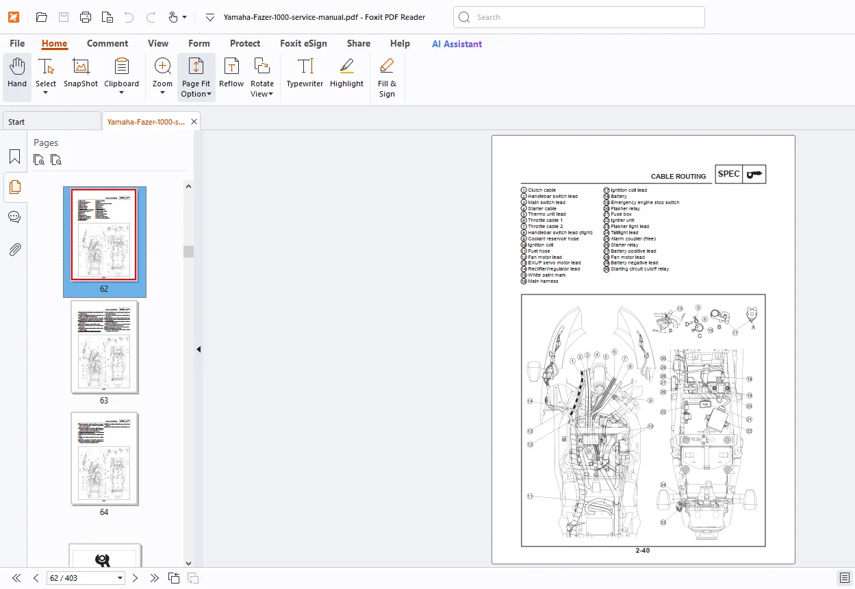
IMAGES PREVIEW OF THE MANUAL:
TABLE OF CONTENTS:
Yamaha FZS1000(N) 2001 Service Manual 5LV1-AE1 – PDF DOWNLOAD
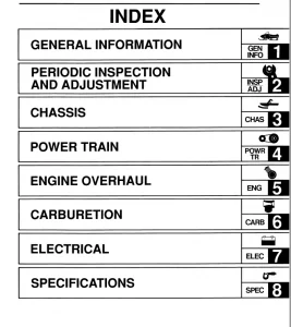
TABLE OF CONTENTS 0
GENERAL INFORMATION 10
SPECIFICATIONS 21
PERIODIC CHECKS AND ADJUSTMENTS 66
CHASSIS129
OVERHAULING THE ENGINE204
COOLING SYSTEM295
CARBURETORS310
ELECTRICAL 329
TROUBLESHOOTING392
WIRING DIAGRAM (EUR)402
WIRING DIAGRAM (OCE)403
RETURN (Model List) 0
RETURN (Manual List) 0
DESCRIPTION:
Yamaha FZS1000(N) 2001 Service Manual 5LV1-AE1 – PDF DOWNLOAD
HOW TO USE THIS MANUAL:
This manual is intended as a handy, easy-to-read reference book for the mechanic. Comprehensive explanations of all installation, removal, disassembly, assembly, repair and check procedures are laid out with the individual steps in sequential order.
1 The manual is divided into chapters. An abbreviation and symbol in the upper right corner of each page indicate the current chapter. Refer to “SYMBOLS” on the following page.
2 Each chapter is divided into sections. The current section title is shown at the top of each page, except in Chapter 3 (“Periodic Checks and Adjustments”), where the sub-section title(-s) appears. (In Chapter 3, “Periodic Checks and Adjustments”, the sub-section title appears at the top of each page, instead of the section title.)
3 Sub-section titles appear in smaller print than the section title.
4 To help identify parts and clarify procedure steps, there are exploded diagrams at the start of each removal and disassembly section.
5 Numbers are given in the order of the jobs in the exploded diagram. A circled number indicates a disassembly step.
6 Symbols indicate parts to be lubricated or replaced (see “SYMBOLS”).
7 A job instruction chart accompanies the exploded diagram, providing the order of jobs, names of parts, notes in jobs, etc.
8 Jobs requiring more information (such as special tools and technical data) are described sequentially.
G.B 12/03/25