Yamaha WR200 Service Manual 1992 PDF DOWNLOAD
Original price was: $95.00.$18.95Current price is: $18.95.
Get the official Yamaha WR200 service manual 1992 PDF, featuring detailed Yamaha WR200RD repair guide, off-road motorcycle maintenance instructions, Yamaha enduro bike troubleshooting manual, and comprehensive Yamaha WR series parts diagrams PDF. This owner’s service manual covers engine, chassis, electrical systems, specifications, and regular adjustments for the 1992 WR200RD model, ensuring safe operation and repairs. Essential for enthusiasts tackling DIY fixes
Description
Yamaha WR200 Service Manual 1992 PDF DOWNLOAD
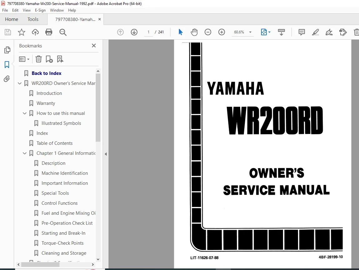
Description: Unlock the complete Yamaha WR200 service manual 1992 PDF, your ultimate Yamaha WR200RD repair guide for maintaining and troubleshooting this iconic off-road motorcycle. Packed with off-road motorcycle maintenance instructions, Yamaha enduro bike troubleshooting manual steps, and Yamaha WR series parts diagrams PDF, this manual provides everything needed for operation, inspection, basic maintenance, and tuning. Issued as the 1991 first edition (applicable to 1992 models), it emphasizes safety, warranty details, and step-by-step procedures with illustrations to help riders and mechanics keep the WR200RD in top condition.
From pre-operation checks to advanced engine overhauls, this Yamaha enduro bike troubleshooting manual ensures you handle issues like clutch adjustments, YPVS system, and brake bleeding confidently. It’s an indispensable resource for off-road enthusiasts, covering competition-use specifics and legal notices for closed-course riding.
File Details:
- Manual Name: Yamaha WR200RD Owner’s Service Manual
- Models Covered: WR200RD
- Year: 1992 (1991 edition)
- Manual PDF Quality: High-resolution with clear text, diagrams, and searchable content
- Number of Pages: 241
Table of Contents: The manual’s table of contents is detailed across multiple pages, organized into six main chapters with subsections for easy navigation. Here’s a neatly categorized extraction:
- Chapter 1: General Information
- Description – 1-1
- Machine Identification – 1-2
- Vehicle Identification Number (For USA and AUS) – 1-2
- Frame Serial Number (Except for USA and AUS) – 1-2
- Engine Serial Number – 1-2
- Important Information – 1-3
- Preparation for Removal and Disassembly – 1-3
- All Replacement Parts – 1-4
- Gaskets, Oil Seals and O-Rings – 1-4
- Lock Washers/Plates and Cotter Pins – 1-4
- Bearings and Oil Seals – 1-4
- Circlips – 1-5
- Special Tools – 1-5
- For Engine Service – 1-5
- For Chassis Service – 1-6
- For Electrical Service – 1-7
- Control Functions – 1-8
- “Engine Stop” Button – 1-8
- Clutch Lever – 1-8
- Shift Pedal – 1-8
- Kick Starter – 1-8
- Throttle Grip – 1-8
- Front Brake Lever – 1-9
- Rear Brake Pedal – 1-9
- Starter Lever (Choke) – 1-9
- Fuel Cock – 1-9
- “Lights” Switch – 1-10
- Odometer – 1-10
- Fuel and Engine Mixing Oil – 1-11
- Pre-Operation Check List – 1-12
- Starting and Break-In – 1-13
- Starting a Cold Engine – 1-13
- Starting a Warm Engine – 1-13
- Break-In Procedures – 1-14
- Torque-Check Points – 1-16
- Cleaning and Storage – 1-18
- Cleaning – 1-18
- Storage – 1-19
- Chapter 2: Specifications
- Specifications – 2-1
- General Specifications – 2-1
- Maintenance Specifications – 2-3
- Engine – 2-3
- Chassis – 2-7
- Electrical – 2-11
- General Torque Specifications – 2-12
- Definition of Units – 2-12
- Cable Routing Diagram – 2-13
- Specifications – 2-1
- Chapter 3: Regular Inspection and Adjustments
- Maintenance Intervals – 3-1
- Coolant Level Inspection – 3-3
- Coolant Replacement – 3-4
- Radiator Cap Inspection – 3-6
- Radiator Cap Opening Pressure Inspection – 3-7
- Cooling System Inspection – 3-7
- Clutch Adjustment – 3-8
- Throttle Cable Adjustment – 3-8
- YPVS Cable Adjustment – 3-9
- Air Filter Cleaning – 3-10
- Transmission Oil Level Inspection – 3-13
- Transmission Oil Replacement – 3-13
- Idle Speed Adjustment – 3-14
- Brake System Air Bleeding – 3-15
- Front Brake Adjustment – 3-16
- Brake Pad Inspection – 3-16
- Brake Fluid Level Inspection – 3-17
- Rear Brake Adjustment – 3-17
- Sprockets Inspection – 3-18
- Drive Chain Inspection – 3-18
- Drive Chain Slack Adjustment – 3-20
- Front Fork Inspection – 3-21
- Front Fork Oil Seal and Dust Seal Cleaning – 3-22
- Front Fork Compression Damping Force Adjustment – 3-22
- Rear Shock Absorber Inspection – 3-23
- Rear Shock Absorber Spring Preload Adjustment – 3-23
- Rear Shock Absorber Rebound Damping Force Adjustment – 3-24
- Rear Shock Absorber Compression Damping Force Adjustment – 3-25
- Tire Pressure Check – 3-26
- Spokes Inspection and Tightening – 3-26
- Wheel Inspection – 3-27
- Steering Head Inspection and Adjustment – 3-27
- Lubrication – 3-30
- Spark Plug Inspection – 3-31
- Headlight Beam Adjustment – 3-32
- Chapter 4: Engine
- Seat, Fuel Tank, Side Covers, Exhaust Pipe and Silencer – 4-1
- Preparation for Removal – 4-1
- Radiator Hoses – 4-2
- Preparation for Removal – 4-2
- Carburetor and Reed Valve – 4-3
- Preparation for Removal – 4-3
- Note on Removal and Reassembly – 4-4
- Removal Points – 4-4
- Throttle Valve – 4-4
- Inspection – 4-5
- Carburetor – 4-5
- Needle Valve – 4-5
- Throttle Valve – 4-6
- Float Arm Height – 4-6
- Float – 4-7
- Reed Valve – 4-7
- Assembly and Installation – 4-7
- Reed Valve – 4-7
- Carburetor – 4-8
- Carburetor Installation – 4-9
- Cylinder Head, Cylinder and Piston – 4-11
- Preparation for Removal – 4-11
- Note on Removal and Reassembly – 4-12
- Removal Points – 4-12
- Radiator Pipe 1 – 4-12
- Pulley – 4-13
- Piston and Piston Ring – 4-14
- Power Valve – 4-14
- Inspection – 4-14
- Cylinder Head – 4-14
- Cylinder – 4-15
- Piston – 4-16
- Piston Pin and Small End Bearing – 4-16
- Piston Ring – 4-18
- Piston Clearance – 4-19
- Combination of Piston and Cylinder – 4-19
- Power Valve – 4-20
- Power Valve Hole on Cylinder – 4-20
- Assembly and Installation – 4-21
- Power Valve – 4-21
- Piston Ring and Piston – 4-22
- Cylinder Head and Cylinder – 4-23
- Clutch, Primary Driven Gear and Primary Drive Gear – 4-27
- Preparation for Removal – 4-27
- Note on Removal and Reassembly – 4-28
- Removal Points – 4-28
- Primary Drive Gear – 4-28
- Clutch Boss – 4-29
- Push Level Axle – 4-29
- Inspection – 4-29
- Clutch Housing and Boss – 4-29
- Primary Driven Gear – 4-29
- Primary Drive Gear and Driven Gear – 4-30
- Clutch Spring – 4-30
- Friction Plate – 4-30
- Clutch Plate – 4-30
- Push Lever Axle and Push Rod – 4-31
- Assembly and Installation – 4-31
- Push Level Axle – 4-31
- Clutch – 4-31
- Kick Axle and Shift Shaft and Primary Drive Gear – 4-35
- Preparation for Removal – 4-35
- Note on Removal and Reassembly – 4-36
- Removal Points – 4-36
- Kick Axle Assembly – 4-36
- Inspection – 4-36
- Kick Axle – 4-36
- Kick Axle and Kick Gear – 4-37
- Kick Gear and Kick Idle Gear – 4-37
- Kick Gear Clip – 4-37
- Shift Shaft – 4-37
- Stopper Lever – 4-37
- Assembly and Installation – 4-38
- Stopper Lever – 4-38
- Shift Shaft – 4-38
- Kick Axle Assembly – 4-38
- Kick Idle Gear – 4-39
- CDI Magneto – 4-41
- Preparation for Removal – 4-41
- Note on Removal and Reassembly – 4-42
- Removal Points – 4-42
- Rotor – 4-42
- Inspection – 4-42
- CDI Magneto – 4-42
- Assembly and Installation – 4-43
- CDI Magneto – 4-43
- Engine Removal – 4-45
- Preparation for Removal – 4-45
- Note on Removal and Reassembly – 4-46
- Removal Points – 4-46
- Drive Sprocket – 4-46
- Engine Removal – 4-46
- Assembly and Installation – 4-47
- Engine Installation – 4-47
- Crankcase and Crankshaft – 4-49
- Preparation for Removal – 4-49
- Note on Removal and Reassembly – 4-50
- Removal Points – 4-50
- Balancer Weight Gear – 4-50
- Crankcase – 4-51
- Crankshaft – 4-51
- Inspection – 4-52
- Crankcase – 4-52
- Crankshaft – 4-52
- Balancer Weight Gear and Balancer Drive Gear – 4-53
- Balancer Weight – 4-53
- Assembly and Installation – 4-53
- Crankshaft – 4-53
- Transmission, Shift Cam and Shift Fork – 4-57
- Preparation for Removal – 4-57
- Note on Removal and Reassembly – 4-58
- Removal Points – 4-58
- Transmission – 4-58
- Inspection – 4-58
- Gears – 4-58
- Bearing – 4-59
- Shift Fork and Shift Cam – 4-59
- Assembly and Installation – 4-60
- Transmission – 4-60
- Shift Cam and Shift Fork – 4-61
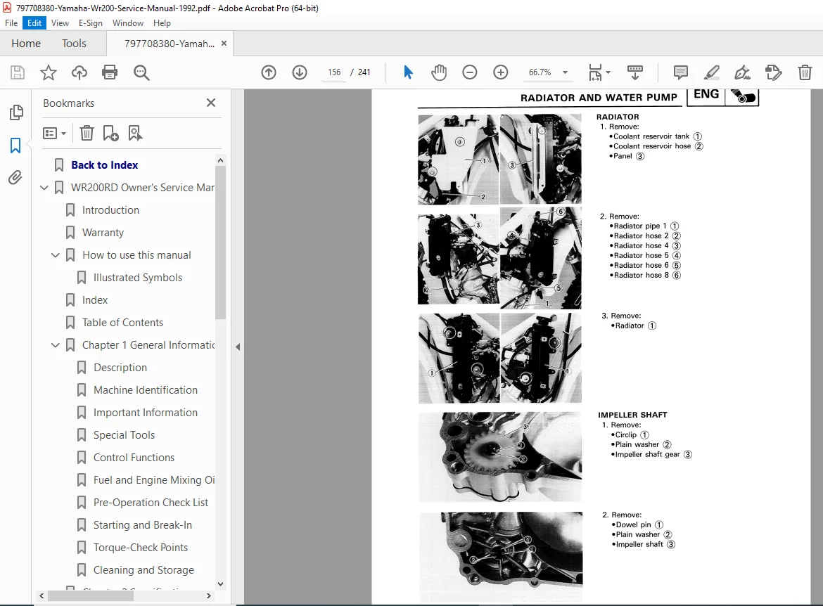
- Radiator and Water Pump – 4-63
- Preparation for Removal – 4-63
- Note on Removal and Reassembly – 4-64
- Removal Points – 4-64
- Radiator – 4-65
- Impeller Shaft – 4-65
- Oil Seal – 4-66
- Inspection – 4-66
- Radiator – 4-66
- Impeller Shaft – 4-66
- Impeller Shaft Gear – 4-66
- Oil Seal – 4-66
- Assembly and Installation – 4-67
- Oil Seal – 4-67
- Impeller Shaft – 4-67
- Seat, Fuel Tank, Side Covers, Exhaust Pipe and Silencer – 4-1
- Chapter 5: Chassis
- Front Wheel – 5-1
- Preparation for Removal – 5-1
- Removal Points – 5-2
- Wheel Bearing (If Necessary) – 5-2
- Inspection – 5-2
- Front Wheel – 5-2
- Assembly and Installation – 5-3
- Front Wheel – 5-3
- Rear Wheel – 5-5
- Preparation for Removal – 5-5
- Removal Points – 5-6
- Rear Wheel – 5-6
- Wheel Bearing (If Necessary) – 5-6
- Inspection – 5-6
- Rear Wheel – 5-6
- Assembly and Installation – 5-7
- Rear Wheel – 5-7
- Front Brake – 5-11
- Preparation for Removal – 5-11
- Removal Points – 5-12
- Caliper – 5-12
- Caliper Piston – 5-13
- Piston Seal Kit – 5-13
- Master Cylinder Kit – 5-13
- Inspection – 5-14
- Master Cylinder – 5-14
- Caliper – 5-14
- Brake Disc – 5-15
- Brake Hose – 5-15
- Assembly and Installation – 5-15
- Brake Pad – 5-15
- Caliper Piston – 5-16
- Caliper – 5-17
- Master Cylinder Kit – 5-18
- Master Cylinder – 5-19
- Brake Disc – 5-20
- Brake Fluid – 5-20
- Rear Brake – 5-23
- Preparation for Removal – 5-23
- Removal Points – 5-24
- Caliper – 5-24
- Caliper Piston – 5-24
- Piston Seal Kit – 5-24
- Brake Pedal – 5-25
- Master Cylinder Kit – 5-26
- Inspection – 5-26
- Master Cylinder – 5-26
- Caliper – 5-26
- Brake Disc – 5-27
- Brake Hose – 5-27
- Assembly and Installation – 5-27
- Brake Pad – 5-28
- Caliper Piston – 5-29
- Caliper – 5-29
- Master Cylinder Kit – 5-30
- Master Cylinder – 5-31
- Brake Disc – 5-33
- Brake Fluid – 5-33
- Front Fork – 5-35
- Preparation for Removal – 5-35
- Removal Points – 5-36
- Cap Bolt – 5-36
- Handling Note – 5-37
- Base Valve – 5-37
- Oil Seal – 5-37
- Inspection – 5-38
- Damper Rod – 5-38
- Base Valve – 5-39
- Fork Spring – 5-39
- Inner Tube – 5-39
- Outer Tube – 5-40
- Cap Bolt – 5-40
- Assembly and Installation – 5-40
- Front Fork Assembly – 5-40
- Installation – 5-46
- Steering – 5-49
- Preparation for Removal – 5-49
- Removal Points – 5-50
- Headlight – 5-50
- Ring Nut – 5-50
- Inspection – 5-51
- Bearing – 5-51
- Steering Shaft – 5-51
- Assembly and Installation – 5-52
- Under Bracket – 5-52
- Swingarm – 5-57
- Preparation for Removal – 5-57
- Note on Removal and Reassembly – 5-58
- Removal Points – 5-58
- Swingarm – 5-58
- Inspection – 5-59
- Swingarm – 5-59
- Relay Arm – 5-59
- Swingarm Side Clearance – 5-59
- Assembly and Installation – 5-61
- Swingarm – 5-61
- Rear Shock Absorber – 5-63
- Preparation for Removal – 5-63
- Notes on Disposal (Yamaha Dealers Only) – 5-64
- Removal Points – 5-65
- Rear Shock Absorber – 5-65
- Spring (Rear Shock Absorber) – 5-65
- Inspection – 5-66
- Damper Rod/Shock Absorber/ Spring/Spring Guide – 5-66
- Assembly and Installation – 5-66
- Spring (Rear Shock Absorber) – 5-66
- Rear Shock Absorber – 5-67
- Front Wheel – 5-1
- Chapter 6: Electrical
- Electrical Components and Wiring Diagram – 6-1
- Electrical Components – 6-1
- Wiring Diagram – 6-1
- Ignition System – 6-2
- Inspection Steps – 6-2
- Spark Gap Test – 6-3
- Couplers and Leads Connection Inspection – 6-3
- “Engine Stop” Button Inspection – 6-3
- Ignition Coil Inspection – 6-4
- CDI Magneto Inspection – 6-5
- CDI Unit Inspection – 6-5
- Lightning System – 6-6
- Inspection Steps – 6-6
- Bulb Inspection – 6-7
- “Lights” Switch Inspection – 6-7
- Lighting Coil Inspection – 6-7
- Out-Put Voltage Inspection – 6-7
- Couplers and Leads Connection Inspection – 6-8
- YPVS System – 6-9
- Inspection Steps – 6-9
- Servomotor Inspection – 6-10
- Electrical Components and Wiring Diagram – 6-1
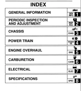
No separate index is present; the detailed TOC and chapter symbols serve as navigation aids.
Revive your Yamaha WR200 with this essential Yamaha WR200 service manual 1992 PDF—download instantly to access expert off-road motorcycle maintenance instructions and Yamaha enduro bike troubleshooting manual, empowering you to perform repairs confidently and hit the trails without delay!