Yamaha XS1100 H/SH/LH Service Manual PDF (Repair/Engine/Wiring ’81)
Original price was: $60.00.$25.95Current price is: $25.95.
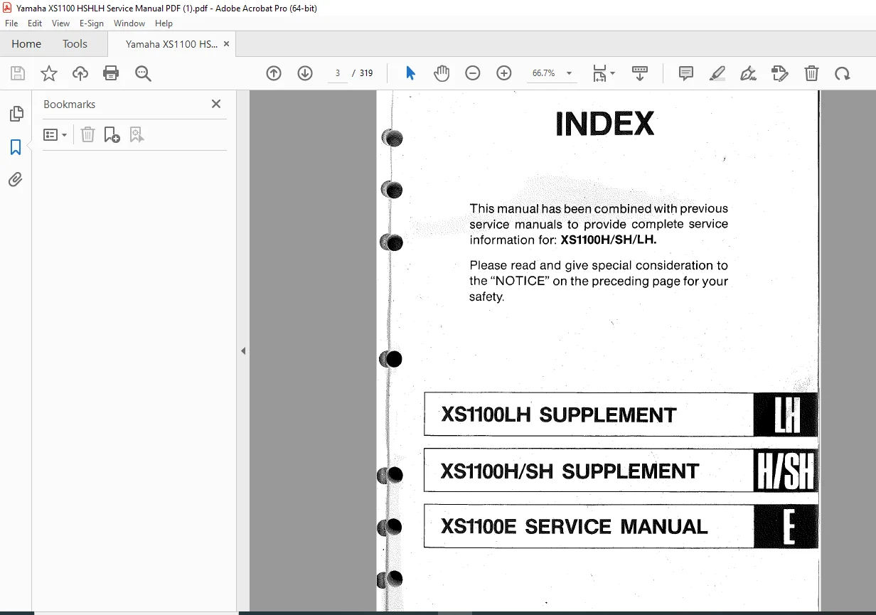
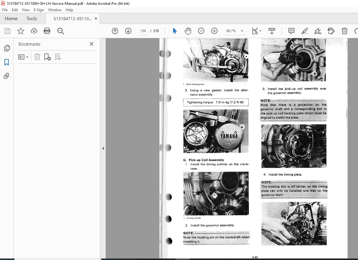
Keep your classic Yamaha XS1100 (H/SH/LH models) running strong! This is the official Yamaha Service Manual PDF download (LIT-11616-01-92). Forget the basic stuff, this is the full factory tech guide. Covers the complete engine rebuild, XS1100 carburetor sync and tuning, transmission, final drive service, electrical system with Yamaha XS1100H wiring diagram, chassis, and all specs. Essential for any XS Eleven owner doing their own work.
Description
Yamaha XS1100 H/SH/LH Service Manual – PDF DOWNLOAD (Repair/Engine/Wiring ’81)
IMAGES:
Product Description
Main Product Title:
Yamaha XS1100 H/SH/LH Service Manual PDF – Official 1981 XS Eleven Factory Repair Manual (LIT-11616-01-92)
Product Description:
The Official Factory Manual for Your Yamaha XS Eleven
If you own or work on one of the mighty Yamaha XS Eleven models – the XS1100H, XS1100SH (Special), or XS1100LH (Midnight Special) from 1981 – you need accurate factory specifications and procedures. This is the Official Yamaha XS1100 H/SH/LH Service Manual (LIT-11616-01-92) – the exact same PDF that Yamaha dealership mechanics used back in the day. It’s the ultimate comprehensive guide for maintenance, repair, and complete overhauls of these legendary motorcycles.
The XS Eleven – Factory Technical Documentation
The XS1100 series represents Yamaha’s flagship four-cylinder superbike from the late 1970s and early 1980s. Known for their powerful inline-four engines, shaft final drive, and smooth road manners, these bikes require precise maintenance and repair procedures. This manual provides everything you need to keep your XS Eleven running perfectly.
Complete Technical Coverage
This manual dives deep into every system of your XS1100:
- Complete engine teardown and rebuild procedures (DOHC inline-four)
- Critical maintenance procedures including XS1100 valve adjustment procedure and cam timing
- Fuel system comprehensive coverage with detailed XS1100 carburetor sync and tuning for the four Mikuni carbs
- Transmission and clutch service (5-speed gearbox, wet multi-plate clutch)
- Shaft final drive (complete service and maintenance)
- Complete electrical system breakdown essential for Yamaha XS1100H electrical troubleshooting
- Charging system (three-phase alternator and regulator/rectifier)
- Ignition system (T.C.I./Transistorized Controlled Ignition)
- Starting system (electric starter motor and relay circuits)
- Complete wiring diagrams (separate diagrams for H and SH/LH models)
- Chassis, suspension, and brakes (air-adjustable front fork, dual disc brakes)
Everything is covered with detailed diagrams, factory specifications, wear tolerances, and critical torque values. This is the definitive Yamaha XS1100 Special repair manual you need.
🔧 Complete Manual Contents
Official Factory Service Manual (296 Pages)
Chapter 1: General Information
- Machine Identification
- Frame number location and decoding
- Engine serial number location
- VIN structure
- Model year identification
- Production date codes
- Model Features
- XS1100H (Standard) features
- XS1100SH (Special) features and differences
- XS1100LH (Midnight Special) features and differences
- Model-specific equipment
- Color and graphics variations
- Detailed Specifications
- General Specifications:
- Dimensions (length, width, height)
- Wheelbase
- Ground clearance
- Seat height
- Dry weight (by model)
- Fuel capacity
- Oil capacity (engine, final drive)
- Engine Specifications:
- Engine type (DOHC inline-four, 4-stroke)
- Displacement (1,101cc / 1,101cm³)
- Bore and stroke (71.5 x 68.6mm)
- Compression ratio
- Maximum power output
- Maximum torque
- Carburetor specifications (4x Mikuni BS34)
- Ignition system (T.C.I.)
- Starting system (electric)
- Lubrication system (wet sump)
- Valve train specifications
- Chassis Specifications:
- Frame type (double cradle)
- Front fork type (air-adjustable telescopic)
- Front fork travel
- Rear suspension type (dual shocks)
- Rear suspension travel
- Tire sizes (front/rear)
- Brake types (dual front disc, single rear disc)
- Final drive type (shaft drive)
- Gear ratios (5-speed transmission)
- Electrical Specifications:
- Battery specifications (12V)
- Alternator output
- Headlight specifications
- Fuse ratings
- Bulb specifications by location
- General Specifications:
- Special Tools
- Complete special tools list with part numbers
- Tool descriptions and applications
- Alternative tools or methods where applicable
- Measurement equipment requirements
- Performance Data
- Speed range in each gear
- Power curves
- Torque curves
- Fuel consumption data
- Performance specifications
Chapter 2: Periodic Inspections and Adjustments
- Introduction
- Importance of scheduled maintenance
- Service record keeping
- Safety precautions during maintenance
- General maintenance guidelines
- Maintenance Interval Chart
- Initial service requirements (break-in period)
- Time-based service intervals (months)
- Mileage-based service intervals (kilometers/miles)
- Comprehensive task checklist by interval
- Severe service modifications
- Engine Maintenance
- Valve Clearance Check and Adjustment:
- Valve cover removal
- Rotor cover removal for TDC location
- Finding TDC for each cylinder
- Measuring valve clearance (intake/exhaust)
- Clearance specifications
- Shim selection and replacement
- Shim size chart
- Reassembly procedures
- Tappet Adjustment:
- Inspection procedures
- Wear measurement
- Replacement criteria
- Idle Speed Adjustment:
- Warm-up requirements
- Throttle stop screw adjustment
- Target idle RPM specification
- Carburetor Synchronization:
- Synchronization tool setup
- Vacuum gauge connection points
- Engine warm-up requirements
- Idle synchronization procedure
- Mid-range synchronization check
- Adjustment screw locations
- Final verification
- Spark Plug Service:
- Plug removal procedures
- Reading plug condition
- Heat range identification
- Gap specification (0.7-0.8mm)
- Recommended plug types (NGK BP7ES or equivalent)
- Torque specification
- Installation procedures
- Compression Test:
- Test preparation (engine warm, plugs removed, throttle open)
- Testing procedure
- Compression pressure specification
- Cylinder-to-cylinder variation limits
- Low compression diagnosis
- Ignition Timing Check:
- Timing mark locations
- Static timing procedure
- Dynamic timing with strobe light
- Timing specification (degrees BTDC)
- T.C.I. timing advance characteristics
- Air Cleaner Service:
- Element access and removal
- Cleaning procedures (foam element)
- Element oil application
- Element inspection
- Installation
- Valve Clearance Check and Adjustment:
- Chassis Maintenance
- Clutch Adjustment:
- Cable free play measurement
- Adjustment at handlebar lever
- Adjustment at engine case
- Free play specification (10-15mm at lever)
- Cable lubrication
- Brake Service:
- Front Brakes (Dual Disc):
- Brake pad inspection and measurement
- Pad minimum thickness
- Fluid level check (DOT 3 or 4)
- Lever free play adjustment
- Caliper operation check
- Rear Brake (Single Disc):
- Pad inspection
- Pedal free play adjustment
- Fluid level check
- Operation verification
- Front Brakes (Dual Disc):
- Steering Head Bearing:
- Play check procedure
- Adjustment procedure
- Bearing preload verification
- Steering smoothness check
- Drive Shaft Oil:
- Oil level check procedure
- Drain and refill procedure
- Oil specification (SAE 80W-90 gear oil)
- Capacity specification
- Seal inspection
- Wheels and Tires:
- Tire pressure specifications (cold)
- Tread depth inspection
- Tire wear patterns
- Wheel bearing play check
- Rim runout inspection
- Spoke tension (if applicable)
- Suspension Adjustment:
- Front Fork (Air-Adjustable):
- Air pressure specifications
- Pressure adjustment procedure
- Valve core location
- Fork oil level verification
- Rear Shock Absorbers:
- Spring preload adjustment
- Damping adjustment (if equipped)
- Ride height measurement
- Front Fork (Air-Adjustable):
- General Chassis Inspection:
- Frame inspection for cracks
- Swing arm bearing play
- Fastener torque verification
- Stand operation
- Clutch Adjustment:
- Electrical System Maintenance
- Battery Service:
- Electrolyte level check
- Specific gravity testing
- Terminal cleaning
- Charging procedures
- Load testing
- Battery installation/removal
- Fuse Inspection:
- Fuse box location
- Fuse ratings by circuit
- Checking procedures
- Replacement procedures
- Headlight Beam Adjustment:
- Aim adjustment procedure
- Horizontal adjustment
- Vertical adjustment
- Proper beam pattern
- Battery Service:
- Lubrication
- Complete lubrication schedule
- Lubrication point diagram
- Recommended lubricants by location
- Cable lubrication procedures
- Control pivot points
- Swing arm pivot
- Drive shaft splines
- Wheel bearings
- Steering head bearings
Chapter 3: Engine Overhauling
- Engine Removal and Installation
- Preparation:
- Safety precautions
- Required tools and equipment
- Drain procedures (oil, coolant if applicable, fuel)
- Removal Procedure:
- Exhaust system removal (4-into-2 system)
- Carburetor removal (4-carb bank)
- Cable and hose disconnection
- Electrical connector disconnection
- Engine mounting bolt removal sequence
- Engine extraction from frame
- Lifting and support considerations
- Installation Procedure:
- Engine positioning in frame
- Mounting bolt installation sequence
- Torque specifications for mounts
- Reconnection of all systems
- Fluid refilling
- Initial startup procedures
- Preparation:
- Engine Disassembly
- External Components:
- Side cover removal (alternator, clutch)
- Oil pan/sump removal
- Oil filter removal
- Oil cooler removal (if equipped)
- Camshaft Removal:
- Cam chain tensioner release
- Camshaft cap removal sequence
- Camshaft extraction (intake and exhaust)
- Cam chain removal
- Chain guide inspection
- Cylinder Head:
- Cylinder head bolt removal sequence (critical)
- Head removal from block
- Head gasket removal
- Valve components (covered in inspection)
- Cylinders and Pistons:
- Cylinder removal from crankcase
- Piston pin circlip removal
- Piston removal from connecting rods
- Piston ring removal
- Cylinder base gasket removal
- Oil Pump:
- Oil pump cover removal
- Pump rotor removal
- Drive gear removal
- Relief valve removal
- Clutch:
- Clutch cover removal
- Pressure plate spring removal
- Friction and steel plate removal
- Clutch basket removal
- Primary driven gear removal
- Shifter Mechanism:
- Shift lever removal
- External shift mechanism disassembly
- Shift shaft removal
- Crankcase Splitting:
- Crankcase bolt removal sequence (critical)
- Case separation procedure
- Special considerations for inline-four engine
- Transmission:
- Main shaft removal
- Counter shaft removal
- Shift drum removal
- Shift fork removal
- Gear cluster disassembly
- Crankshaft:
- Crankshaft removal from cases
- Connecting rod inspection access
- Main bearing removal (if needed)
- External Components:
- Inspection and Repair
- Cylinder Head:
- Warpage measurement (multiple points)
- Maximum warpage specification
- Valve seat inspection
- Valve guide inspection and measurement
- Guide replacement procedures
- Seat cutting specifications
- Combustion chamber inspection
- Valves and Valve Train:
- Valve stem diameter measurement
- Stem-to-guide clearance specification
- Valve face inspection
- Valve seat width measurement
- Valve spring free length measurement
- Spring tension testing at specified height
- Spring squareness check
- Valve stem seal condition
- Shim bucket inspection
- Camshafts:
- Cam lobe height measurement (intake/exhaust)
- Lobe wear limits
- Journal diameter measurement
- Bearing clearance specification
- Camshaft runout measurement
- Cam chain wear measurement (20-pin method)
- Cylinder Block:
- Bore diameter measurement (top, middle, bottom)
- Out-of-round measurement
- Taper measurement
- Wear limits and oversizes available
- Honing requirements and procedure
- Deck height measurement
- Pistons and Rings:
- Piston diameter measurement (perpendicular to pin)
- Piston-to-cylinder clearance specification
- Ring end gap measurement in bore
- Ring groove wear measurement
- Ring side clearance specification
- Piston pin bore inspection
- Pin-to-piston clearance
- Piston skirt inspection
- Crankshaft:
- Main journal diameter measurement
- Crankpin diameter measurement
- Journal out-of-round measurement
- Crankshaft runout measurement
- Connecting rod side clearance
- Connecting rod big end radial clearance
- Small end inspection
- Main bearing inspection
- Rod bearing inspection
- Clutch Components:
- Friction plate thickness measurement
- Plate minimum thickness specification
- Warpage check on steel plates
- Spring free length measurement
- Basket gear teeth inspection
- Hub spline wear inspection
- Pushrod straightness check
- Transmission Components:
- Gear tooth inspection
- Dog engagement surface inspection
- Gear bore and shaft diameter measurement
- Gear-to-shaft clearance
- Shift fork wear measurement
- Fork-to-gear clearance specification
- Shift drum groove inspection
- Detent mechanism inspection
- Bearing inspection (all transmission bearings)
- Oil Pump:
- Rotor tip clearance measurement
- Body clearance measurement
- Rotor side clearance
- Wear limits for all measurements
- Relief valve spring testing
- Crankcase:
- Mating surface condition
- Bearing bore inspection
- Seal seat inspection
- Thread condition
- Stud integrity
- Cylinder Head:
- Engine Assembly and Adjustment
- Assembly Preparation:
- Parts cleaning (detailed procedures)
- Gasket and seal preparation
- Oil passage verification
- Bearing installation techniques
- Seal installation techniques
- Assembly lubrication
- Crankshaft Installation:
- Main bearing installation in cases
- Crankshaft positioning
- Main bearing cap installation
- End play measurement and specification
- Transmission Assembly:
- Gear installation on shafts
- Shift fork installation
- Shift drum installation
- Proper positioning and timing
- Shift mechanism operation check
- Crankcase Joining:
- Gasket or sealant application
- Case alignment procedures
- Bolt installation sequence (critical)
- Torque specifications and sequence
- Case rotation check after assembly
- Oil Pump Installation:
- Drive gear installation
- Pump rotor installation
- Pump cover installation with new gasket
- Oil pressure relief valve installation
- Piston and Cylinder Assembly:
- Piston ring installation (top, second, oil rings)
- Ring gap positioning (staggered)
- Piston pin installation with new circlips
- Piston installation on connecting rods
- Cylinder base gasket installation
- Cylinder installation (careful ring compression)
- Cylinder head gasket installation
- Cylinder Head Installation:
- Head positioning on block
- Head bolt installation in proper sequence
- Multi-stage torque tightening sequence
- Final torque specifications
- Camshaft Installation:
- Cam chain installation
- Camshaft positioning (timing marks)
- Camshaft cap installation in sequence
- Cap bolt torque specifications
- Cam timing verification
- Chain tensioner installation and adjustment
- Clutch Assembly:
- Primary driven gear installation
- Clutch basket installation
- Steel and friction plate installation (alternating)
- Pressure plate installation
- Spring installation and torque
- Clutch cover installation with new gasket
- External Component Installation:
- Oil pan installation with new gasket
- Oil filter installation
- Alternator cover with new gasket
- Shift mechanism installation
- Critical Checks Before Installation:
- Engine rotation check (smooth, no binding)
- Oil pressure verification
- Compression test
- Leak-down test (optional but recommended)
- Assembly Preparation:
Chapter 4: Carburetion
- Carburetor System Overview
- Four Mikuni BS34 constant velocity carburetors
- Linked throttle operation
- Choke system (enrichener)
- Function descriptions
- Carburetor Diagrams
- Complete exploded view diagram (all four carbs)
- Individual component identification
- Jet locations and sizes
- Circuit identification
- Removal
- Fuel tank removal
- Airbox removal
- Throttle cable disconnection
- Choke cable disconnection
- Fuel line disconnection
- Carburetor bank removal from manifolds
- Individual carburetor separation (if needed)
- Disassembly
- Float bowl removal (all four)
- Main jet removal
- Pilot jet removal
- Jet needle and slide removal
- Float and needle valve removal
- Mixture screw access (pilot screw)
- Complete component separation
- Cleaning
- Carburetor cleaner usage guidelines
- Body and passage cleaning
- Jet cleaning (never use wire)
- Compressed air drying
- Fuel passage verification
- O-ring and gasket inspection
- Inspection
- Body for cracks or damage
- Slide bore wear
- Slide diaphragm inspection
- Jet needle wear inspection
- Needle jet (emulsion tube) wear
- Main jet orifice inspection
- Pilot jet orifice inspection
- Float condition (no fuel inside)
- Needle valve and seat inspection
- Spring condition
- Throttle shaft wear
- Assembly
- Component installation sequence
- Gasket and O-ring replacement
- Proper jet installation (hand tight)
- Float installation
- Needle and slide installation
- Diaphragm installation (proper orientation)
- Float bowl installation
- Installation
- Carburetor bank assembly (if separated)
- Manifold installation
- Throttle cable connection and routing
- Choke cable connection
- Fuel line connection
- Airbox installation
- Fuel tank installation
- Adjustments
- Float Height Adjustment:
- Measurement procedure (with gauge or ruler)
- Float height specification (millimeters)
- Tang bending adjustment method
- Verification procedure
- Pilot Screw (Mixture Screw) Adjustment:
- Initial setting (turns out from lightly seated)
- Warm engine requirements
- Fine-tuning procedure
- Optimal setting determination
- Final position recording
- Idle Speed Adjustment:
- Master idle adjust screw location
- Engine warm-up requirement
- Target idle RPM (1,000-1,100 RPM typical)
- Adjustment procedure
- Carburetor Synchronization:
- Vacuum gauge tool setup (4-gauge)
- Gauge connection to sync ports
- Engine warm-up to operating temperature
- Idle synchronization first
- Individual adjuster locations (between carbs)
- Balancing procedure
- Mid-range synchronization verification
- Final idle speed setting
- Test ride verification
- Float Height Adjustment:
- Fuel System Components
- Fuel Petcock:
- Removal from tank
- Disassembly
- Screen cleaning
- Diaphragm inspection
- Vacuum operation check
- Reassembly and installation
- Fuel Tank:
- Removal procedures
- Cleaning procedures
- Inspection for rust/damage
- Sealing (if needed)
- Installation
- Fuel Petcock:
Chapter 5: Chassis
- Wheels
- Front Wheel:
- Brake caliper removal
- Front axle removal
- Wheel removal from forks
- Installation procedure
- Axle torque specification
- Caliper installation and torque
- Rear Wheel:
- Rear brake caliper removal
- Drive shaft coupling disconnection
- Axle nut removal
- Wheel removal
- Installation procedure
- Drive shaft reconnection
- Axle nut torque specification
- Wheel Inspection:
- Rim runout measurement (radial and lateral)
- Maximum runout specification
- Rim damage inspection
- Hub inspection
- Bearing Service:
- Bearing removal techniques
- Bearing inspection (roughness, play, rust)
- Seal removal
- New bearing installation (proper tools/techniques)
- Seal installation
- Bearing lubrication (appropriate grease)
- Tire Service:
- Tire removal from rim
- Bead breaking techniques
- Tire inspection (wear, damage, age)
- Tube inspection (if applicable – these are tubeless)
- Tire installation procedures
- Bead seating
- Balancing procedures
- Pressure specifications
- Front Wheel:
- Brake System
- Front Brake System (Dual Disc):
- Caliper Service:
- Caliper removal
- Pad removal and inspection
- Pad minimum thickness
- Piston removal (compressed air method)
- Seal and dust boot replacement
- Bore inspection and cleaning
- Piston inspection
- Reassembly with brake fluid
- Caliper installation
- Master Cylinder Service:
- Reservoir cover removal
- Fluid level check
- Master cylinder removal from handlebar
- Disassembly
- Piston and cup seal inspection
- Bore inspection
- Reassembly with new seals
- Installation
- Brake Disc Inspection:
- Disc thickness measurement
- Minimum thickness specification
- Runout measurement
- Maximum runout specification
- Surface condition inspection
- Caliper Service:
- Rear Brake System (Single Disc):
- Similar procedures to front system
- Pedal height adjustment
- Master cylinder service (rear-specific)
- Caliper service
- Disc inspection
- Brake Bleeding:
- Proper bleeding procedure
- Sequence for front system (right then left, or vice versa)
- Fluid type specification (DOT 3 or DOT 4)
- Air removal techniques
- Pedal/lever feel verification
- Front Brake System (Dual Disc):
- Final Drive / Drive Shaft
- Drive Shaft Removal:
- Rear wheel removal
- Drive shaft coupling disconnection
- Drive shaft extraction from swing arm
- Disassembly:
- U-joint disassembly
- Spline inspection
- Bearing inspection
- Seal removal
- Inspection:
- U-joint cross bearing inspection
- Spline wear measurement
- Shaft straightness check
- Bearing condition
- Seal condition
- Assembly:
- Bearing installation
- Seal installation
- U-joint reassembly with grease
- Spline lubrication
- Installation:
- Shaft installation in swing arm
- Coupling connection
- Rear wheel installation
- Drive Shaft Oil Change:
- Drain plug location
- Drain procedure
- Fill plug location
- Oil specification (SAE 80W-90)
- Capacity specification
- Level verification
- Drive Shaft Removal:
- Steering System
- Handlebar:
- Removal procedures
- Control lever removal
- Switch housing service
- Installation and alignment
- Torque specifications
- Steering Head:
- Adjustment:
- Fork removal for full service
- Stem nut loosening
- Bearing adjustment procedure
- Preload verification
- Tightening specifications
- Lock nut torque
- Steering smoothness check
- Bearing Service:
- Complete disassembly
- Upper bearing removal
- Lower bearing removal
- Race removal from head tube
- Bearing and race inspection
- New bearing installation
- Race installation (proper tools)
- Lubrication (appropriate grease)
- Reassembly
- Adjustment
- Adjustment:
- Handlebar:
- Front Fork
- Fork Removal:
- Front wheel removal
- Brake caliper removal
- Fender removal
- Upper triple clamp loosening
- Lower triple clamp loosening
- Fork tube removal
- Fork Disassembly:
- Air valve removal
- Fork cap removal (special socket may be needed)
- Spring removal
- Damper rod bolt removal (from bottom)
- Slider separation
- Damper unit removal
- Fork Inspection:
- Tube straightness check (roll on flat surface)
- Chrome surface inspection for pitting
- Slider bore inspection
- Bushing wear measurement
- Spring free length measurement
- Damper operation check
- Oil seal inspection
- Fork Assembly:
- New seal installation (seal driver required)
- Dust seal installation
- Bushing lubrication
- Damper rod installation
- Damper bolt installation with new crush washer
- Fork tube insertion
- Spring installation
- Fork oil specification and quantity (per tube)
- Oil level measurement from top (specification)
- Fork cap installation and torque
- Air valve installation
- Fork Installation:
- Fork tube installation in triple clamps
- Alignment procedure (loosen clamps, compress forks, tighten)
- Upper clamp torque specification
- Lower clamp torque specification
- Fender installation
- Brake caliper installation
- Front wheel installation
- Air Pressure Adjustment:
- Recommended air pressure range
- Pressure adjustment procedure
- Left/right balance importance
- Effect on ride quality
- Fork Removal:
- Rear Suspension
- Shock Absorber:
- Removal procedure (upper and lower mounting)
- Visual inspection (leaks, damage)
- Damping test (compression/rebound)
- Spring preload adjustment
- Installation and torque specifications
- Swing Arm:
- Removal procedure (pivot bolt, chain, drive shaft)
- Bearing inspection
- Dust seal inspection
- Bushing inspection (if applicable)
- Lubrication
- Installation
- Pivot bolt torque specification
- Play check and adjustment
- Shock Absorber:
- Frame
- Frame inspection for cracks or damage
- Critical stress point inspection
- Engine mount inspection
- Swing arm pivot inspection
- Steering head inspection
Chapter 6: Electrical
- Electrical System Overview
- Complete electrical components diagram
- System descriptions
- Voltage and current specifications
- Safety precautions
- Checking Switches and Connections
- Visual inspection procedures
- Continuity testing with multimeter
- Switch operation verification
- Connector inspection and cleaning
- Terminal condition inspection
- Dielectric grease application
- Battery Service
- Battery location and access
- Removal procedures
- Electrolyte level check and refilling
- Specific gravity testing (charged state determination)
- Charging procedures (charging rate and duration)
- Load testing procedures
- Terminal cleaning (baking soda solution)
- Terminal protection
- Installation and secure mounting
- Charging System
- System Description:
- Three-phase alternator operation
- Regulator/rectifier function
- Output voltage regulation
- Alternator Output Check:
- Test equipment required
- Connection points
- No-load test procedure
- AC voltage output specification (by RPM)
- Load test procedure
- Stator coil resistance test
- Regulator/Rectifier Check:
- Regulated voltage test at battery
- Voltage specification (13.5-15V typical at 5,000 RPM)
- Rectifier diode testing
- Replacement procedures
- System Description:
- Ignition System (T.C.I.)
- System Description:
- Transistorized Controlled Ignition operation
- Pickup coil function
- T.C.I. unit signal processing
- Ignition coil operation (2 coils, each fires 2 cylinders)
- Spark timing and advance
- T.C.I. Unit Check:
- Testing limitations (often replacement test only)
- Visual inspection of unit
- Connector inspection
- Mounting location
- Pickup Coil Check:
- Pickup coil location (in alternator cover)
- Resistance measurement
- Resistance specification
- Air gap measurement
- Air gap specification
- Signal output test (AC voltage)
- Ignition Coil Check:
- Primary winding resistance measurement
- Primary resistance specification
- Secondary winding resistance measurement
- Secondary resistance specification
- Insulation test
- Coil mounting and location
- Spark Plug Caps:
- Resistance measurement
- Resistance specification (typically 5kΩ)
- Replacement procedures
- Wire condition inspection
- System Description:
- Electric Starter System
- System Components:
- Starter motor
- Starter relay (magnetic switch)
- Start button
- Clutch switch (safety interlock)
- Neutral switch
- Sidestand switch (safety interlock)
- Starter Motor Service:
- Removal from engine
- Disassembly procedures
- Brush inspection and measurement
- Minimum brush length specification
- Commutator inspection
- Commutator service (cleaning, turning if needed)
- Armature testing (continuity, insulation)
- Field coil testing
- Bearing inspection
- Reassembly
- Installation
- Starter Relay Check:
- Relay location
- Relay operation test (audible click)
- Coil resistance measurement
- Contact continuity test
- Replacement procedures
- Safety Switch Checks:
- Clutch switch continuity test (lever pulled/released)
- Neutral switch continuity test (in/out of neutral)
- Sidestand switch continuity test (up/down)
- Proper operation logic verification
- System Components:
- Lighting System
- Headlight:
- Bulb replacement (H4 or similar)
- High beam operation
- Low beam operation
- Wattage specification
- Aim adjustment
- Taillight/Brake Light:
- Bulb replacement
- Dual-filament operation
- Running light function
- Brake light function
- Brake light switch adjustment
- Instrument Lights:
- Bulb replacement procedures
- Access to instrument cluster
- Bulb specifications
- Self-Cancelling Turn Signal System:
- System description and operation
- Cancel timer unit
- Operation logic
- Troubleshooting procedures
- Headlight:
- Signal and Accessory Systems
- Turn Signal System:
- Turn signal switch testing
- Flasher relay operation
- Flash rate specification
- Bulb specifications
- Lens replacement
- Horn:
- Horn button testing
- Horn operation check
- Adjustment (if applicable)
- Replacement procedures
- Fuse and Relay Box:
- Fuse box location
- Individual fuse identification
- Fuse ratings by circuit
- Relay locations and functions
- Fuel Gauge/Sender:
- Fuel gauge operation
- Sender unit testing (resistance across range)
- Sender removal from tank
- Gauge testing procedures
- Turn Signal System:
- Wiring Diagrams
- Complete Color Wiring Diagram – XS1100H:
- Full schematic with color codes
- Component locations
- Connector identification
- Ground points
- Fuse and relay positions
- Complete Color Wiring Diagram – XS1100SH/LH:
- Model-specific schematic
- Color codes
- Component differences from H model
- Additional equipment wiring
- Wire Color Code Key:
- Abbreviation meanings
- Color identification
- Tracer stripe notation
- Complete Color Wiring Diagram – XS1100H:
Chapter 7: Appendices
- Specifications Recap
- Quick reference specifications table
- All critical dimensions
- All critical clearances
- All critical torque values
- General Torque Specifications
- Standard bolt/nut torque by size and grade
- Special torque requirements
- Thread-locking compound usage
- Torque sequence diagrams
- Conversion Tables
- Metric to imperial conversions
- Torque conversions (N⋅m to ft-lb to kgf⋅m)
- Pressure conversions (kPa, psi, bar, kg/cm²)
- Temperature conversions (°C to °F)
- Measurement conversions
- Cable Routing Diagrams
- Throttle cable routing
- Clutch cable routing
- Choke cable routing
- Brake cable routing (if applicable)
- Electrical harness routing
- Proper routing to prevent interference or damage
📄 Technical Specifications
- Manual Name: Yamaha XS1100 H/SH/LH Service Manual
- Manual Part Number: LIT-11616-01-92 / 4R0-28197-10
- Publication Date: June 1980
- Models Covered:
- XS1100H (Standard)
- XS1100SH (Special)
- XS1100LH (Midnight Special)
- Model Year: Primarily 1981 models (H/SH/LH designation)
- Engine Type: DOHC inline-four, 4-stroke
- Displacement: 1,101cc (1,101cm³)
- Bore x Stroke: 71.5mm x 68.6mm
- Carburetion: 4x Mikuni BS34 constant velocity
- Transmission: 5-speed
- Final Drive: Shaft drive
- Brakes: Dual front disc, single rear disc
- Suspension: Air-adjustable telescopic fork, dual rear shocks
- Format: Excellent quality scan, searchable, printable PDF with full bookmarks
- Pages: 296
- Language: English
- Quality: Very clear diagrams and text, professional factory documentation
Who Needs This Manual?
This official factory service manual is essential for:
- XS1100 Owners (DIY maintenance and repair)
- Classic Yamaha Enthusiasts (XS series collectors)
- Vintage Motorcycle Mechanics (specializing in 1970s-80s Japanese bikes)
- Motorcycle Restoration Specialists (professional restorers)
- Motorcycle Service Shops (multi-brand repair facilities)
- Yamaha Parts Suppliers (accurate parts identification)
- Mechanical Students (learning inline-four engine systems)
- XS Eleven Clubs and Communities (technical reference resource)
What Makes the XS1100 Special
The Yamaha XS1100 represents the pinnacle of Yamaha’s inline-four superbike development:
- Powerful DOHC Inline-Four – 1,101cc of smooth, torquey power
- Shaft Final Drive – Low-maintenance, reliable power delivery
- Advanced Features – Air-adjustable front fork, dual front disc brakes
- Three Variants – H (Standard), SH (Special), LH (Midnight Special)
- Legendary Reliability – Known for durability when properly maintained
- Cult Following – Strong enthusiast community and parts support
These bikes are now highly collectible and cherished by vintage motorcycle enthusiasts. Proper maintenance using factory procedures ensures longevity and riding enjoyment.
Why This Manual is Essential
Factory-Level Technical Knowledge:
- Official Yamaha engineering documentation
- Exact specifications and tolerances
- Correct service procedures from 1980
- Complete theory of operation for all systems
- Professional troubleshooting methodology
Complete System Coverage:
- DOHC inline-four engine (complete overhaul)
- Valve adjustment procedures (critical for engine longevity)
- Four-carburetor synchronization (essential for smooth operation)
- Shaft drive service (unique maintenance requirements)
- T.C.I. ignition system (electronic ignition troubleshooting)
- Complete electrical system with model-specific wiring diagrams
Prevent Costly Mistakes:
- Correct valve shim selection and installation
- Proper camshaft timing procedures
- Critical bolt torque specifications
- Accurate clearances and tolerances
- Carburetor synchronization techniques
- Electrical system troubleshooting
Keep Your XS Eleven Running Strong:
- Period-correct factory specifications
- Complete maintenance schedules
- Parts identification via exploded diagrams
- Model-specific information for H/SH/LH variants
- Troubleshooting for common issues
⚠️ Important Notice
This is a professional-grade factory service manual intended for individuals with mechanical knowledge and experience. Working on inline-four motorcycle engines requires proper tools, cleanliness, attention to detail, and understanding of four-stroke operation. Always follow safety procedures, properly dispose of fluids, use appropriate lifting equipment, and wear personal protective equipment.
Technical Note: This manual primarily covers 1981 model year XS1100H, XS1100SH, and XS1100LH variants. While many procedures apply to earlier XS1100 models (1978-1980), there are some differences in specifications and components. Always verify model-specific information for your exact year and variant.
Key Benefits:
✅ Official Yamaha Factory Documentation – Not aftermarket or generic
✅ Three Models Covered – H, SH (Special), LH (Midnight Special)
✅ 296 Pages of comprehensive technical information
✅ Complete Engine Overhaul – DOHC inline-four rebuild procedures
✅ Valve Adjustment Procedures – Critical shim-under-bucket service
✅ Carburetor Synchronization – Four-carb balance procedures
✅ Shaft Drive Service – Complete maintenance and repair
✅ T.C.I. Ignition System