★ TRUSTED BY 321,897+ PROFESSIONALS WORLDWIDE
🏢
Trusted Business
Verified & Licensed
🛡️
Virus Free Files
100% Safe Downloads
🔒
Secure Payment
SSL Protected
Instant Delivery
Available Immediately

Yamaha YZF-R6T YZF-R6TC Service Manual – PDF DOWNLOAD

$15.95

Yamaha YZF-R6T YZF-R6TC Service Manual – PDF DOWNLOAD

Instant PDF Download
Available immediately
💾
Save to Your Device
Download & keep forever
🛡️
Antivirus Scanned
100% virus-free
🌍
Trusted Worldwide
175,000+ customers

Description

Yamaha YZF-R6T YZF-R6TC Service Manual – PDF DOWNLOAD

FILE DETAILS:

Yamaha YZF-R6T YZF-R6TC Service Manual – PDF DOWNLOAD

Language : English
Pages : 64
Downloadable : Yes
File Type : PDF

IMAGES PREVIEW OF THE MANUAL:

TABLE OF CONTENTS:

Yamaha YZF-R6T YZF-R6TC Service Manual – PDF DOWNLOAD

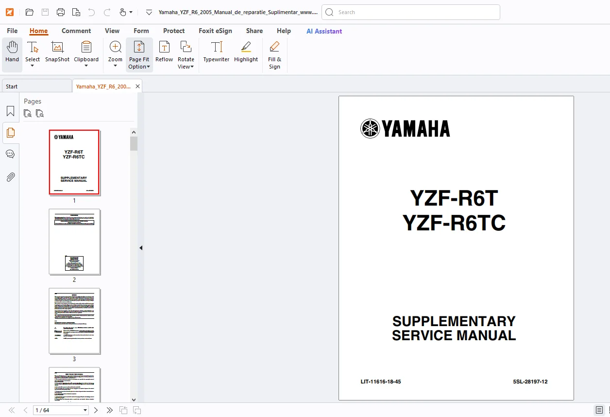
YZR-R6T/TC Supplementary Service Manual 1
How to use this Manual 4
Contents 6
General Information 8
Special Tools 8
Specifications 9
General Specifications 9
Engine Specifications 9
Chassis Specifications10
Electrical Specifications11
Tightening Torques12
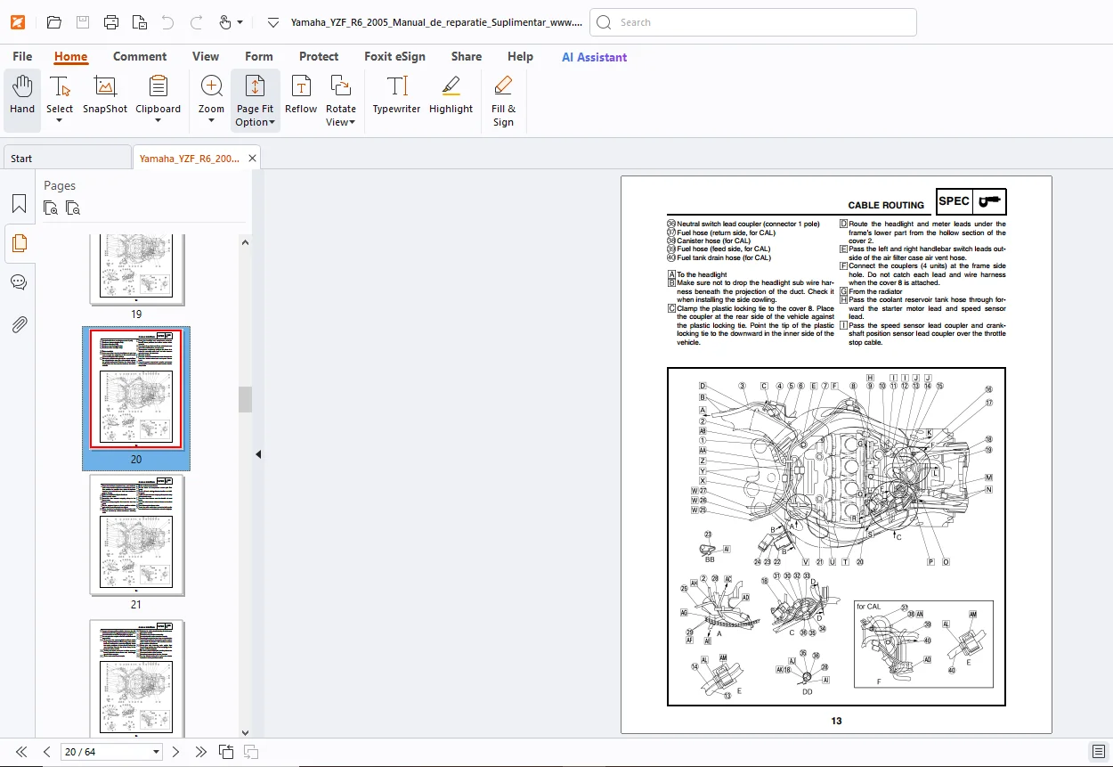
Cable Routing13
Periodic Checks and Adjustments27
Chassis31
Front Wheel and Brake Discs31
Front and Rear Brakes32
Front Fork40
Swingarm and Drive Chain50
Cooling System52
Radiator52
Electrical System54
Electrical Starting System54
Cooling System58
Wiring Diagram62

DESCRIPTION:

Yamaha YZF-R6T YZF-R6TC Service Manual – PDF DOWNLOAD

HOW TO USE THIS MANUAL:

This manual is intended as a handy, easy-to-read reference book for the mechanic. Comprehensive explanations of all installation, removal, disassembly, assembly, repair and check procedures are laid out with the individual steps in sequential order.
1 The manual is divided into chapters. An abbreviation and symbol in the upper right corner of each page indicate the current chapter. Refer to “SYMBOLS”.
2 Each chapter is divided into sections. The current section title is shown at the top of each page, except in
Chapter 3 (“PERIODIC CHECKS AND ADJUSTMENTS”), where the sub-section title(s) appears. 3 Sub-section titles appear in smaller print than the section title.
4 To help identify parts and clarify procedure steps, there are exploded diagrams at the start of each removal and disassembly section.
5 Numbers are given in the order of the jobs in the exploded diagram. A circled number indicates a disassembly step.
6 Symbols indicate parts to be lubricated or replaced. Refer to “SYMBOLS”.
7 A job instruction chart accompanies the exploded diagram, providing the order of jobs, names of parts, notes in jobs, etc. 8 Jobs requiring more information (such as special tools and technical data) are described sequentially.

G.B 13/03/25

What Our Customers Say

★★★★★ Live reviews from customers
Loading customer reviews...
0
    0
    Your Cart
    Your cart is emptyReturn to Shop
    🛒
    Recently Purchased
    🕒 verified order