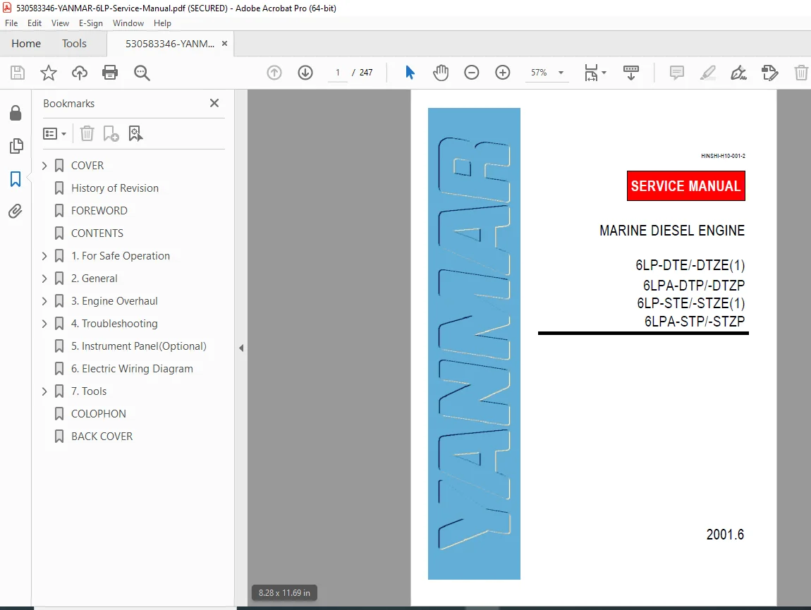
Yanmar 6LP Marine Diesel Engine Service Repair Manual 6LP-DTE 6LPA-STP PDF
Original price was: $95.00.$28.95Current price is: $28.95.
Complete factory service manual for Yanmar 6LP series marine diesel engines covering 6LP-DTE, 6LP-DTZE, 6LPA-DTP, 6LPA-DTZP, 6LP-STE, 6LP-STZE, 6LPA-STP, and 6LPA-STZP models. Comprehensive technical documentation includes complete disassembly/assembly procedures, timing belt service, valve adjustments, injection timing, turbocharger overhaul, specifications, torque values, and troubleshooting guides. Essential professional reference for marine diesel mechanics and boat technicians.
Description
Yanmar 6LP Marine Diesel Engine Service Repair Manual 6LP-DTE 6LPA-STP PDF DOWNLOAD
DESCRIPTION
This is the complete official Yanmar 6LP Series Marine Diesel Engine Service Manual (Document HINSHI-H10-001-2, June 2001) for professional marine diesel engines. This comprehensive factory workshop manual provides professional-grade maintenance, repair, and overhaul information for authorized marine technicians servicing Yanmar 6-cylinder diesel engines in commercial and recreational marine applications.
Models Covered by This Service Manual
Yanmar 6LP Series Marine Diesel Engines:
Turbocharged Models:
- 6LP-DTE – Turbocharged marine diesel engine
- 6LP-DTZE(1) – Turbocharged variant with emissions control
- 6LPA-DTP – Turbocharged professional marine diesel
- 6LPA-DTZP – Turbocharged professional variant
Naturally Aspirated/Standard Models:
- 6LP-STE – Standard marine diesel engine
- 6LP-STZE(1) – Standard variant with emissions control
- 6LPA-STP – Professional standard marine diesel
- 6LPA-STZP – Professional standard variant
Engine Type:
- 6-cylinder inline configuration
- 4-stroke diesel engine
- Marine application (commercial and recreational)
- Turbocharged and naturally aspirated variants
- Direct injection system
Complete Manual Contents (247 Pages)
This Yanmar 6LP service manual PDF is organized into comprehensive sections covering all service procedures:
SECTION 1: GENERAL INFORMATION (Inferred)
- Engine model identification
- Serial number location
- Safety precautions
- General service information
- Tool requirements
- Specifications overview
SECTION 2: PERIODIC MAINTENANCE (Inferred)
- Maintenance schedules
- Service intervals
- Inspection procedures
- Lubrication requirements
- Filter replacement
- Preventive maintenance
SECTION 3: SERVICE PROCEDURES
3.1 Engine Overview (Inferred)
- Engine construction
- Component identification
- Operating principles
- System descriptions
3.2 Complete Engine Disassembly and Assembly
3.2.1-3.2.8 Initial Disassembly (Inferred)
- Peripheral component removal
- Accessory removal
- Preparation for major disassembly
3.2.9 Assembly of Piston and Connecting Rod
- 3.2.9.1 Assemble the piston and connecting rod
- 3.2.9.2 Install the piston rings
- 3.2.9.3 Install the crank pin bearing
3.2.10 Assembly of Cylinder Block
- 3.2.10.1 Install oil nozzle and check valve for piston cooling
- 3.2.10.2 Install the main bearings
- 3.2.10.3 Place the crankshaft on the cylinder block
- 3.2.10.4 Install the thrust bearing
- 3.2.10.5 Install the main bearing caps
- 3.2.10.6 Inspect the thrust clearance of the crankshaft
- 3.2.10.7 Install the piston and connecting rod assembly
- 3.2.10.8 Install the connecting rod caps
- 3.2.10.9 Check the connecting rod thrust clearance
- 3.2.10.10 Install the rear oil seal case
3.2.11 Next Assembly Procedures
- 3.2.11.1 Install the engine mounting bracket
- 3.2.11.2 Install the timing gear case
- 3.2.11.3 Install the oil pan
- 3.2.11.4 Install the rear end plate
- 3.2.11.5 Install the flywheel
- 3.2.11.6 Install the flywheel housing with set bolts
- 3.2.11.7 Upside down the engine on engine stand
- 3.2.11.8 Install the thermostat
- 3.2.11.9 Install the alternator and bracket assembly
- 3.2.11.10 Install the fresh water pump
- 3.2.11.11 Install the cylinder head
- 3.2.11.12 Install the timing belt and pulley
- 3.2.11.13 Remove the engine from engine stand
- 3.2.11.14 Install the turbocharger oil pipe
- 3.2.11.15 Install the oil cooler assembly, oil dipstick and guide
- 3.2.11.16 Install the sender units and warning switches
- 3.2.11.17 Install the fuel injection pump
- 3.2.11.18 Install the sea water pump
- 3.2.11.19 Install the lube oil filter
3.3 Timing Belt
3.3.1 Components
- Timing belt parts identification
- Belt specifications
- Related components
3.3.2 Removal of Timing Belt
- 3.3.2.1 Remove the timing belt cover
- 3.3.2.2 Set No.1 cylinder at bottom dead center (BDC)
- 3.3.2.3 Remove the timing belt
- 3.3.2.4 Remove the idler pulley
- 3.3.2.5 Remove No.2 camshaft timing pulley
- 3.3.2.6 Remove the bonnet
- 3.3.2.7 Remove No.1 camshaft timing pulley
3.3.3 Checking of Timing Belt
- 3.3.3.1 Checking the timing belt (wear, cracks, tension)
- 3.3.3.2 Inspect the idler pulley
- 3.3.3.3 Inspect the tension spring and tensioner
3.3.4 Installation of Timing Belt
- 3.3.4.1 Install No.1 camshaft timing pulley
- 3.3.4.2 Install the bonnet
- 3.3.4.3 Install No.2 camshaft timing pulley
- 3.3.4.4 Install the idler pulley
- 3.3.4.5 Set No.1 cylinder to bottom dead center (BDC)
- 3.3.4.6 Install the timing belt
- 3.3.4.7 Install the tension spring (6LP-DTE series)
- 3.3.4.8 Install the timing belt tensioner (6LP-STE series)
- 3.3.4.9 Inspect the valve timing
- 3.3.4.10 Install the timing belt cover
3.4 Timing Gear
3.4.1 Components
- Timing gear assembly parts
3.4.2 Removal of Timing Gear
- 3.4.2.1 Remove V-belt for fresh water pump and alternator
- 3.4.2.2 Loosen the crankshaft pulley
- 3.4.2.3 Remove the timing belt and pulley
- 3.4.2.4 Remove the camshaft oil seal retainer
- 3.4.2.5 Remove the crankshaft pulley
- 3.4.2.6 Remove the alternator adjusting bar
- 3.4.2.7 Remove the timing gear cover
- 3.4.2.8 Remove the oil pump drive shaft gear
- 3.4.2.9 Inspect thrust clearance of the idler gear
- 3.4.2.10 Remove the idler gear
- 3.4.2.11 Remove the fuel injection pump drive gear
- 3.4.2.12 Remove the crankshaft timing gear
3.4.3 Inspection of Timing Gear
- 3.4.3.1 Check the idler gear
- 3.4.3.2 Check fuel injection pump drive gear bearing
- 3.4.3.3 Replace fuel injection pump drive gear bearing as needed
- 3.4.3.4 Inspect backlash of the timing gear
3.4.4 Replacement of Crankshaft Front Oil Seal
- 3.4.4.1 Replace the crankshaft front oil seal
3.4.5 Replacement of Fuel Injection Pump Drive Gear Oil Seal
- 3.4.5.1 Replace fuel injection pump drive gear oil seal
3.4.6 Installation of Timing Gear
- 3.4.6.1 Install the crankshaft timing gear
- 3.4.6.2 Install the fuel injection pump drive gear
- 3.4.6.3 Install the idler gear
- 3.4.6.4 Install the oil pump drive shaft gear
- 3.4.6.5 Install the timing gear cover
- 3.4.6.6 Install the alternator adjusting bar
- 3.4.6.7 Install the crankshaft pulley
- 3.4.6.8 Install camshaft oil seal retainer
- 3.4.6.9 Install timing pulleys and timing belt
- 3.4.6.10 Tighten crankshaft pulley bolt
- 3.4.6.11 Install V-belt for fresh water pump and alternator
3.5 Valve Clearance Inspection and Adjustment
3.5.1 Inspection of Valve Clearance
- 3.5.1.1 Remove the bonnet
- 3.5.1.2 Set No.1 cylinder to top dead center (TDC)
- 3.5.1.3 Inspect the valve clearance
3.5.2 Adjustment of Valve Clearance
- 3.5.2.1 Adjust the valve clearance
- 3.5.2.2 Install the bonnet
3.6 Inspection and Adjustment of Injection Timing
3.6.1 Inspection of Injection Timing
- 3.6.1.1 Set No.1 or No.6 cylinder at TDC (compression stroke)
- 3.6.1.2 Install plunger stroke measuring tool and dial indicator
- 3.6.1.3 Inspect the injection timing
3.6.2 Adjustment of Injection Timing
- 3.6.2.1 Adjust the injection timing
- 3.6.2.2 Tighten union nuts for fuel injection pipe
- 3.6.2.3 Start engine and check for fuel oil leakage
3.7 Service Specifications
3.7.1 Engine Adjusting Standards
- Valve clearances
- Injection timing specifications
- Belt tensions
- Critical adjustments
3.7.2 Service Standards
- Wear limits
- Clearance specifications
- Tolerance values
- Replacement criteria
3.7.3 Nut and Bolt Tightening Torque (Page 3-75)
- Complete torque specifications
- Fastener grades
- Tightening sequences
- Critical bolt torques
3.8 Turbocharger
3.8.1 Construction and Function
- 3.8.1.1 Overview of construction and function
- 3.8.1.1.1 Turbine
- 3.8.1.1.2 Blower (compressor)
- 3.8.1.1.3 Bearing system
- 3.8.1.1.4 Sealing structure at blower side
3.8.2 Components (RHE6W Turbocharger)
- Complete parts identification
- Exploded view diagrams
3.8.3 Service Specifications
- 3.8.3.1 Service standards
- 3.8.3.2 Nut and bolt tightening torque (Page 3-80)
3.8.4 Periodic Inspection Procedure
- 3.8.4.1 Periodic inspection intervals
- 3.8.4.2 Inspection procedure
- 3.8.4.2.1 Running of turbine shaft
- 3.8.4.2.2 Inspection of turbine shaft play
3.8.5 Disassembly Procedure
- 3.8.5.1 Preparation for disassembly
- 3.8.5.2 Inspection before disassembly
- 3.8.5.2.1 Check turbine and compressor impellers for interference
- 3.8.5.2.2 Measure the turbine shaft play (Page 3-84)
- 3.8.5.3 Disassembly steps
- 3.8.5.3.1 Remove the boost hose
- 3.8.5.3.2 Remove the compressor housing
- 3.8.5.3.3 Remove the compressor impeller
- 3.8.5.3.4 Remove the seal plate
- 3.8.5.3.5 Remove the turbine housing
- 3.8.5.3.6 Pull off the turbine shaft
- 3.8.5.3.7 Remove thrust bearing and thrust bushing
- 3.8.5.3.8 Remove the floating bearing
- 3.8.5.3.9 Remove the seal ring
3.8.6 Cleaning and Checking Procedures
- 3.8.6.1 Cleaning
- 3.8.6.1.1 Checking before cleaning
- 3.8.6.1.2 Cleaning procedure
- 3.8.6.2 Inspection procedure (detailed component checks)
- 3.8.6.2.1 Compressor housing
- 3.8.6.2.2 Turbine housing
- 3.8.6.2.3 Compressor impeller
- 3.8.6.2.4 Turbine shaft
- 3.8.6.2.5 Thermal insulation plate
- 3.8.6.2.6 Thrust bushing, oil thrower, and thrust bearing
- 3.8.6.2.7 Floating bearing
- 3.8.6.2.8 Bearing housing
- 3.8.6.2.9 Seal plate
- 3.8.6.2.10 Seal rings
- 3.8.6.2.11 Check bolts for deformation
3.8.7 Reassembly Procedure
- 3.8.7.1 Preparation for reassembly
- 3.8.7.1.1 Prepare tools
- 3.8.7.1.2 Replace the parts
- 3.8.7.2 Reassembly steps
- 3.8.7.2.1 Installation of floating bearing
- 3.8.7.2.2 Installation of turbine shaft
- 3.8.7.2.3 Installation of thrust bearing
- 3.8.7.2.4 Installation of turbine housing
- 3.8.7.2.5 Installation of seal plate
- 3.8.7.2.6 Installation of compressor impeller
- 3.8.7.2.7 Installation of compressor housing
- 3.8.7.2.8 Installation of boost hose
- 3.8.7.2.9 Measurement of turbine shaft play
3.8.8 Handling after Disassembly and Reassembly
- 3.8.8.1 Instructions for turbocharger installation
- 3.8.8.1.1 Lubrication path
- 3.8.8.1.2 Intake path
- 3.8.8.1.3 Exhaust path
3.8.9 Troubleshooting
- 3.8.9.1 Excessively dense exhaust smoke
- 3.8.9.2 White exhaust gas color
- 3.8.9.3 Excessive engine oil consumption
- 3.8.9.4 Engine output drop
- 3.8.9.5 Poor (slow) response (starting) of turbocharger
- 3.8.9.6 Abnormal sound or vibration
3.9 Fuel Filter Replacement
3.9.1 Removal of Fuel Filter
- 3.9.1.1 Disconnect water alarm switch connector
- 3.9.1.2 Drain fuel from the fuel filter
- 3.9.1.3 Fuel filter removal
- 3.9.1.4 Remove water alarm switch from fuel filter
3.9.2 Installation of Fuel Filter
- 3.9.2.1 Install water alarm switch to new fuel filter
- 3.9.2.2 Install the new fuel filter
- 3.9.2.3 Install water alarm switch connector
- 3.9.2.4 Fill fuel to the fuel filter
- 3.9.2.5 Start engine to check for fuel leakage
3.10 Fuel Injection Nozzle
3.10.1 Components
- Fuel injection nozzle parts
3.10.2 Removal of Fuel Injection Nozzle
- Nozzle removal procedures
3.10.3 Testing the Fuel Injection Nozzle
- 3.10.3.1 Leak test
- 3.10.3.2 Testing the spray condition
3.10.4 Components of Fuel Injection Nozzle
- Detailed parts breakdown
3.10.5 Disassembly of Fuel Injection Nozzle
- 3.10.5.1 Disassemble the fuel injection nozzle
3.10.6 Cleaning and Inspection of Fuel Injection Nozzle
- 3.10.6.1 Cleaning the nozzle
- Inspection criteria
- Wear limits
ADDITIONAL SECTIONS (247 Pages Total)
Section 4: Cooling System (Inferred)
- Fresh water cooling system
- Sea water cooling system
- Heat exchangers
- Water pumps
- Thermostats
- Hoses and connections
Section 5: Lubrication System (Inferred)
- Oil pump
- Oil cooler
- Oil filters
- Lubrication circuits
- Oil pressure specifications
Section 6: Fuel System (Inferred)
- Fuel injection pump
- Fuel lines
- Fuel filters
- Bleeding procedures
- System adjustments
Section 7: Electrical System (Inferred)
- Starting system
- Charging system
- Alternator
- Starter motor
- Wiring diagrams
- Sensors and switches
Section 8: Troubleshooting (Inferred)
- Engine won’t start
- Poor performance
- Overheating
- Oil pressure issues
- Smoke conditions
- Abnormal noises
Appendices:
- Wiring diagrams
- Hydraulic schematics
- Special tools
- Parts catalogs
- Torque specifications tables
- Conversion charts
Key Technical Features
6-Cylinder Inline Diesel:
- Professional marine application
- Proven reliability
- Compact design
- Efficient combustion
Turbocharger Models (DTE/DTP Series):
- RHE6W turbocharger
- Increased power output
- Improved fuel efficiency
- Water-cooled bearing housing
- Complete overhaul procedures included
Timing Belt System:
- Dual overhead camshaft (DOHC)
- Timing belt drive
- Precise valve timing
- Detailed replacement procedures
- Model-specific tensioner differences
Fuel Injection:
- Direct injection system
- Individual fuel injection nozzles
- Adjustable injection timing
- Plunger-type injection pump
- High-pressure fuel delivery
Cooling System:
- Fresh water cooled
- Heat exchanger equipped
- Sea water pump
- Thermostat controlled
- Efficient heat dissipation
Professional Service Features
Factory Documentation:
- Published by Yanmar (YTSK)
- June 2001 release
- Document HINSHI-H10-001-2
- Same manual used by authorized Yanmar service centers
Comprehensive Coverage:
- Complete disassembly/assembly procedures
- Step-by-step instructions
- Detailed component identification
- Inspection criteria
- Service specifications
- Torque values
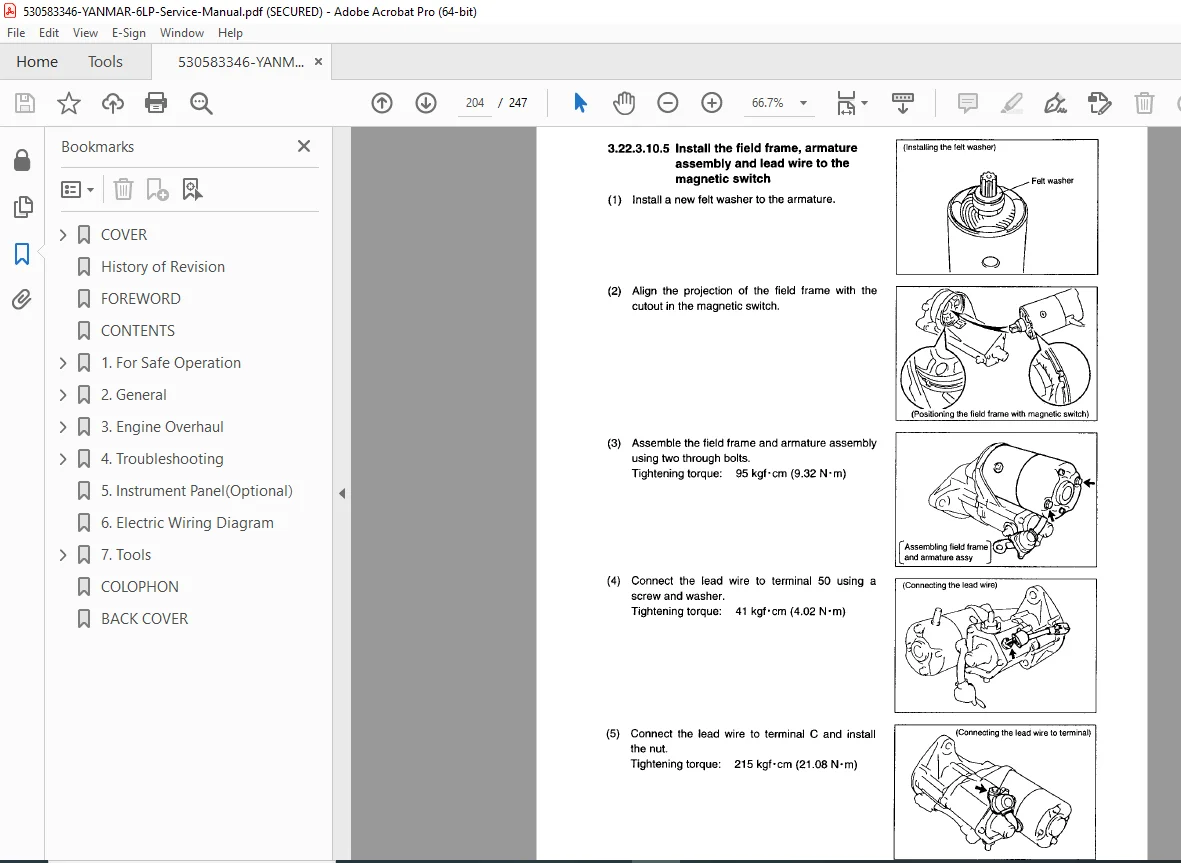
Visual Aids:
- Exploded view diagrams
- Component photographs
- Assembly sequences
- Tool usage illustrations
- Measurement procedures
Who Should Use This Manual?
This marine diesel engine repair guide is essential for:
- Certified marine diesel mechanics
- Authorized Yanmar service technicians
- Yacht and boat service centers
- Commercial vessel maintenance crews
- Marina service departments
- Technical training schools
- Experienced marine engineers
Required Knowledge:
- Marine diesel engine principles
- Fuel injection system understanding
- Turbocharger technology
- Marine cooling systems
- Electrical system diagnostics
- Precision measurement techniques
- Marine safety procedures
Important Service Notes
Critical Marine Equipment: Yanmar 6LP engines are marine propulsion systems requiring:
- Proper service procedures
- Genuine Yanmar parts
- Correct specifications
- Safety awareness
- Environmental compliance
Turbocharger Service:
- Critical clearances must be maintained
- Proper oil supply essential
- Shaft play measurement critical
- Bearing replacement intervals
- Pre-lubrication before startup
Timing System:
- Precise timing belt installation
- Correct valve timing essential
- Injection timing affects performance
- Use specified tools for adjustment
- Verification after service
Safety Considerations:
- Marine environment hazards
- Fuel system pressure
- Hot coolant caution
- Rotating components
- Battery disconnect procedures
FILE DETAILS
| Attribute | Details |
|---|---|
| Manual Name | Yanmar 6LP Series Marine Diesel Engine Service Manual |
| Document Number | HINSHI-H10-001-2 |
| Models Covered | 6LP-DTE, 6LP-DTZE(1), 6LPA-DTP, 6LPA-DTZP, 6LP-STE, 6LP-STZE(1), 6LPA-STP, 6LPA-STZP |
| Engine Type | 6-Cylinder Inline Marine Diesel |
| Configuration | Turbocharged and Naturally Aspirated variants |
| Turbocharger | RHE6W (turbocharged models) |
| Manual Type | Factory Service & Repair Workshop Manual |
| Publication Date | June 2001 (2001.6) |
| File Format | PDF (A4 size pages) |
| File Size | ~10.3 MB |
| Total Pages | 247 pages |
| PDF Quality | High-resolution optimized factory manual |
| Language | English |
| Publisher | Yanmar (YTSK) |
| Security | Print-enabled, copy-protected |