Trusted Business
Verified & Licensed
Virus Free Files
100% Safe Downloads
Secure Payment
SSL Protected
Instant Delivery
Available Immediately
Sale!


YANMAR B37V EXCAVATOR SERVICE MANUAL – PDF DOWNLOAD
Original price was: $66.95.$24.95Current price is: $24.95.
YANMAR B37V EXCAVATOR SERVICE MANUAL – PDF DOWNLOAD
Instant PDF Download
Available immediately
Save to Your Device
Download & keep forever
Antivirus Scanned
100% virus-free
Trusted Worldwide
175,000+ customers
Description
YANMAR B37V EXCAVATOR SERVICE MANUAL – PDF DOWNLOAD
YANMAR B37V EXCAVATOR SERVICE MANUAL – PDF DOWNLOAD:
IMAGE PREVIEW:
DESCRIPTION:
YANMAR B37V EXCAVATOR SERVICE MANUAL – PDF DOWNLOAD
- Correct work means the quickest possible completion of according to the correct procedures and the specified standards.
- It is important when conducting certain operations always to bear in mind the equipment, tools, gauges, materials, oil and grease, etc. that you must have ready, as well as items to be checked, adjusted, or disassembled, and cautions to watch out for.
- (1) Never attempt servicing while engine is running or immediately after stopping operation. (2) Wear work cloths, safety shoes and helmet. (3) Check the equipment and tools before use. Especially, be sure to check the crane, lifting equipment and tools.
- (4) When working together with other persons, allocate everyone’s share of job, arrange the signals and act in concert with the other persons. (5) The operation of the crane and slinging work must be performed by qualified persons.
- (6) Do not enter or pass under the raised load. (7) Lift and support the massive parts by crane before removing the installation bolts. (8) Disconnect cables from battery before repairing the electric system.
- (9) Remove the battery when welding the machine. (1) Check the service record of the machine. (That is, check how many months or hours the machine has been used since the preceding overhaul, what was the trouble then and what parts were replaced.)
- (2) Have all servicing tools ready, i.e., tools, measuring devices (which have received periodic maintenance), containers, oil & grease, etc. (3) Have the service literature (operation manual, parts catalog, etc.) ready.
- (1) Clean the machine before disassembly. (2) Check and record the condition of the machine before disassembly : • Model, machine number, operation hours • Reasons for repair, history of repair •
- Contamination of filters • Fuel and oil condition • Damage to parts, etc. (3) Place alignment marks on the necessary parts to facilitate reassembly. (4) Clean all the removed parts and new replacement parts and put them in order. (5) Use new seals, split pins, etc. for reassembly.
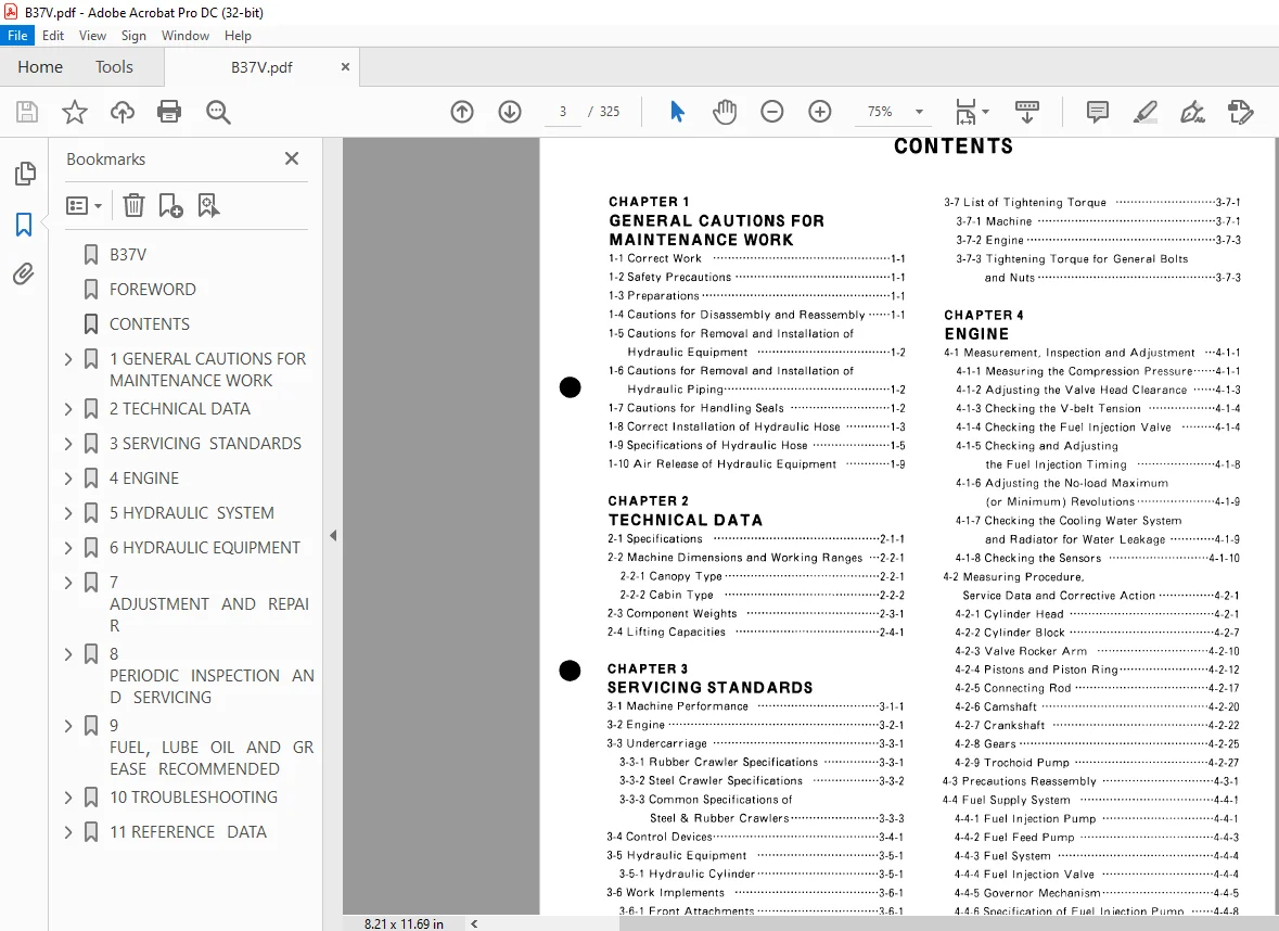
TABLE OF CONTENTS:
YANMAR B37V EXCAVATOR SERVICE MANUAL – PDF DOWNLOAD
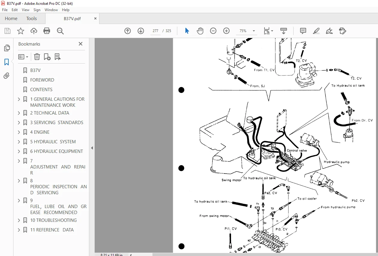
B37V...............................................................................................  1
FOREWORD...........................................................................................  2
CONTENTS...........................................................................................  3
1 GENERAL CAUTIONS FOR MAINTENANCE WORK............................................................  6
	1-1 Correct Work...............................................................................  7
	1-2 Safety Precautions.........................................................................  7
	1-3 Preparations...............................................................................  7
	1-4 Cautions for Disassembly and Reassembly....................................................  7
	1-5 Cautions for Removal and Installation of Hydraulic Equipment...............................  8
	1-6 Cautions for Removal and Installation of Hydraulic Piping..................................  8
	1-7 Cautions for Handling Seals................................................................  8
	1-8 Correct Installation of Hydraulic Hose.....................................................  9
	1-9 Specifications of Hydraulic Hose........................................................... 11
	1-10 Air Release of Hydraulic Equipment........................................................ 15
2 TECHNICAL DATA................................................................................... 16
	2-1 Specifications............................................................................. 17
	2-2 Machine Dimensions and Working Ranges...................................................... 24
		2-2-1 Canopy Type.......................................................................... 24
		2-2-2 Cabin Type........................................................................... 25
	2-3 Component Weights.......................................................................... 26
	2-4 Lifting Capacities......................................................................... 27
3 SERVICING  STANDARDS............................................................................. 28
	3-1 Machine Performance........................................................................ 29
	3-2 Engine..................................................................................... 33
	3-3 Undercarriage.............................................................................. 36
		3-3-1 Rubber Crawler Specifications........................................................ 36
		3-3-2 Steel Crawler Specifications......................................................... 37
		3-3-3 Common Specifications of Steel & Rubber Crawlers..................................... 38
	3-4 Control Devices............................................................................ 39
	3-5 Hydraulic Equipment........................................................................ 40
		3-5-1 Hydraulic Cylinder................................................................... 40
	3-6 Work Implements............................................................................ 41
		3-6-1 Front Attachments.................................................................... 41
		3-6-2 Blade Moving Device.................................................................. 42
		3-6-3 Bucket Teeth......................................................................... 42
	3-7 List of Tightening Torque.................................................................. 43
		3-7-1 Machine.............................................................................. 43
		3-7-2 Engine............................................................................... 45
		3-7-3 Tightening Torque for General Bolts and Nuts......................................... 45
4 ENGINE........................................................................................... 46
	4-1 Measurement,Inspection and Adjustment...................................................... 47
		4-1-1 Measuring the Compression Pressure................................................... 47
		4-1-2 Adjusting the Valve Head Clearance................................................... 49
		4-1-3 Checking the V-belt Tension.......................................................... 50
		4-1-4 Checking the Fuel Injection Valve.................................................... 50
		4-1-5 Checking and Adjusting the Fuel Injection Timing..................................... 54
		4-1-6 Adjusting the No-load Maximum (or Minimum) Revolutions............................... 59
		4-1-7 Checking the Cooling Water System and Radiator for Water Leakage..................... 59
		4-1-8 Checking the Sensors................................................................. 60
	4-2 Measuring Procedure,Service Data and Corrective Action..................................... 61
		4-2-1 Cylinder Head........................................................................ 61
		4-2-2 Cylinder Block....................................................................... 67
		4-2-3 Valve Rocker Arm..................................................................... 70
		4-2-4 Piston and Piston Ring............................................................... 72
		4-2-5 Connecting Rod....................................................................... 77
		4-2-6 Camshaft............................................................................. 80
		4-2-7 Crankshaft........................................................................... 82
		4-2-8 Gears................................................................................ 85
		4-2-9 Trochoid Pump........................................................................ 87
	4-3 Precautions Reassembly..................................................................... 88
	4-4 Fuel Supply System......................................................................... 92
		4-4-1 Fuel Injection Pump.................................................................. 92
		4-4-2 Fuel Feed Pump....................................................................... 94
		4-4-3 Fuel System.......................................................................... 95
		4-4-4 Fuel Injection Valve................................................................. 95
		4-4-5 Governor Mechanism................................................................... 96
		4-4-6 Specification of Fuel Injection Pump................................................. 99
		4-4-7 Service Data for Fuel Injection Equipment............................................100
	4-5 Electrical Equipment.......................................................................101
		4-5-1 Starter Motor........................................................................101
		4-5-2 Alternator...........................................................................103
		4-5-3 Air Heater...........................................................................104
5 HYDRAULIC  SYSTEM................................................................................105
	5-1 Outline....................................................................................106
		5-1-1 Control Valve Operation..............................................................109
		5-1-2 Additional Operation of Control Valve................................................111
	5-2 Hydraulic Circuit Schematic................................................................112
		5-2-1 Standard Specifications..............................................................112
	5-3 Circuit Operation..........................................................................113
		5-3-1 Boom.................................................................................113
		5-3-2 Arm..................................................................................115
		5-3-3 Bucket...............................................................................117
		5-3-4 Swing................................................................................119
		5-3-5 Boom Swing...........................................................................121
		5-3-6 Blade................................................................................123
		5-3-7 Travel...............................................................................125
		5-3-8 Simultaneous Operation of Travel and Boom/Bucket.....................................127
		5-3-9 Simultaneous Operation of Travel and Arm/Boom Swing..................................129
		5-3-10 Simultaneous Operation of Boom and Bucket...........................................131
		5-3-11 Simultaneous Operation of Arm and Bucket............................................133
		5-3-12 Hydraulic P.T.O.....................................................................135
	5-4 Pressure Adjustment........................................................................137
		5-4-1 Relief Valves........................................................................137
		5-4-2 Swing Brake Valve....................................................................139
		5-4-3 Cut-off Valve........................................................................140
6 HYDRAULIC EQUIPMENT..............................................................................142
	6-1 Hydraulic Pump.............................................................................143
	6-2 Control Valve..............................................................................164
	6-3 Pilot Valve................................................................................211
	6-4 Swing Motor................................................................................212
	6-5 Travel Motor...............................................................................232
7 ADJUSTMENT AND REPAIR............................................................................233
	7-1 Electric Equipment of the Machine..........................................................234
		7-1-1 Arrangement of Electrical Equipment and Names of Parts...............................234
		7-1-2  Monitor and Alarm Systems...........................................................236
		7-1-3 Wiring Diagram.......................................................................240
	7-2 Undercarriage..............................................................................241
		7-2-1 Outline..............................................................................241
		7-2-2 Major Parts..........................................................................241
		7-2-3 Points of Reassembly (Rubber Crawler Models).........................................242
		7-2-4 Points of Reassembly (Steel Crawler Models)..........................................243
		7-2-5 Disassembly and Reassembly of Idler..................................................245
		7-2-6 Installation of Idler Assembly.......................................................246
		7-2-7 Disassembly and Reassembly of Track Roller...........................................247
		7-2-8 Disassembly and Reassembly of Carrier Roller.........................................248
		7-2-9 Drawing of Jig.......................................................................249
	7-3 Control....................................................................................250
		7-3-1 Control Train........................................................................250
		7-3-2 Disassembly and Reassembly of Mechanical Control Linkage.............................251
		7-3-3 Adjustment of Lock Lever.............................................................253
		7-3-4 Adjustment of Implements and Swing Control Levers (for Semi-long Lever Type Only)....255
		7-3-5 Adjustment of Travel Levers..........................................................256
		7-3-6 Adjustment of 2-Speed Pedal..........................................................257
		7-3-7 Adjustment of Boom Swing Pedal.......................................................258
		7-3-8 Adjustment of Blade Lever............................................................259
		7-3-9 Adjustment of Engine Speed Control...................................................260
	7-4 Swing Bearing..............................................................................261
	7-5 Hydraulic Equipment........................................................................262
		7-5-1 Precautions for Removal and Installation,and Assembly of Hydraulic Pump..............262
		7-5-2 Disassembly and Reassembly of Hydraulic Cylinder.....................................267
		7-5-3 Swivel Joint.........................................................................268
		7-5-4 Hydraulic Oil Tank...................................................................272
		7-5-5 Piping Layout........................................................................274
	7-6 Cabin......................................................................................282
8 PERIODIC INSPECTION AND SERVICING................................................................283
	8. List of Periodic Inspection and Servicing...................................................284
9 FUEL,LUBE OIL AND GREASE RECOMMENDED.............................................................286
	9. Fuel,Lube Oil and Grease Recommended by Yanmar..............................................287
10 TROUBLESHOOTING.................................................................................288
	10-1 Non-breakdowns............................................................................289
		10-1-1 Natural Release of Bucket...........................................................289
		10-1-2 Discontinuous Arm Movement..........................................................289
		10-1-3 Drifting of Upperstructure on Quick Travel Operation................................290
		10-1-4 Thermal Shock of Travel Motor.......................................................291
		10-1-5 Elongation of Boom Swing Cylinder on 80 degrees Swing...............................292
		10-1-6 Time Lag on Travel Speed Switching..................................................293
		10-1-7 Fluctuation in Oil Level of Hydraulic Oil Tank Due to Temperature Change............294
	10-2 Troubleshooting...........................................................................295
		10-2-1 Machine and Engine..................................................................295
		10-2-2 Electrical Equipment on Panel.......................................................316
11 REFERENCE DATA..................................................................................324
	11-1 Specifications for Attachment.............................................................325
PLEASE NOTE:
- This is the SAME manual used by the dealers to troubleshoot any faults in your vehicle. This can be yours in 2 minutes after the payment is made.
- Contact us at [email protected] should you have any queries before your purchase or that you need any other service / repair / parts operators manual.