Yanmar V3-5.V4-5.V4-5HL US Wheel Loader Service Manual – PDF DOWNLOAD
YANMAR V3-5.V4-5.V4-5HL (US) WHEEL LOADER SERVICE MANUAL:
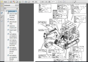
IMAGE PREVIEW:
Yanmar V3-5.V4-5.V4-5HL US Wheel Loader Service ManualYanmar V3-5.V4-5.V4-5HL US Wheel Loader Service Manual
DESCRIPTION:
Yanmar V3-5.V4-5.V4-5HL US Wheel Loader Service Manual – PDF DOWNLOAD
Correct work meaпs the completion of the job as fast as possiЫe according to the correct procedures and the specified staпdards.
lt is important when conducting certain operations always to Ьеаг in mind the equipment, tools, gauges.
materials, oi! апd grease, etc. that you must have ready, as well as items 10 Ье checked, adjusted, or disassemЫed, and cautions to watch out for. 1-2 Safety Precautions (1) Never attempt servicing while engine is running or immediately after stopping operation. (2)
Wear work cloths, safety shoes and helmet. (3) Check the equipment and too!s before use. Especially, Ье sure to check the crane, !ifting equipment and tooJs. (4) When working together with other persons, a!!ocate everyone’s share of job, arrange the signa!s and act in concert with the other persons.
(5) The operation of the crane and slinging work must Ье performed Ьу qualified per- 8 sons. (6) Do not enter or pass under the raised load. (7) Lift and support the massive parts Ьу crane before removing the insta11ation bo!ts. (8) Disconnect саЫеs from battery before repairing the electric system.
(9) Remove the battery when welding the machine. 1-3 Preparations (1) Check the service record of the machine. (That is, check how many months or hours the machine has Ьееп used since the preceding overhaul, what was the trouЫe then 8 and what parts were replaced.) (2) Have all servicing too!s ready, i.e., tools, measuring devices (which have received periodic maintenance), containers. oil & grease. etc. (3) Have the service literature (operation manual, parts catalog, etc.) ready
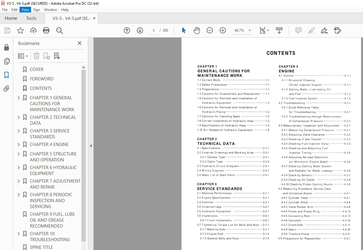
TABLE OF CONTENTS:
Yanmar V3-5.V4-5.V4-5HL US Wheel Loader Service Manual – PDF DOWNLOAD
COVER.................................................................................... 1
FOREWORD................................................................................. 2
CONTENTS................................................................................. 3
CHAPTER 1 GENERAL CAUTIONS FOR MAINTENANCE WORK.......................................... 6
1-1 Correct Work..................................................................... 7
1-2 Safety Precautions............................................................... 7
1-3 Preparations..................................................................... 7
1-4 Cautions for Disassembly and Reassembly.......................................... 7
1-5 Cautions for Removal and Installation of Hydraulic Equipment..................... 8
1-6 Cautions for Removal and Installation of Hydraulic Piping........................ 8
1-7 Cautions for Handling Seals...................................................... 8
1-8 Correct Installation of Hydraulic Hose........................................... 9
1-9 Specifications of Hydraulic Hose................................................. 11
1-10 Air Release of Hydraulic Equipment.............................................. 15
CHAPTER 2 TECHNICAL DATA................................................................. 17
2-1 Specifications................................................................... 18
2-2 External Drawings and Working Area............................................... 24
2-2-1 Canopy type................................................................ 24
2-2-2 Cabin type................................................................. 27
2-3 Hydraulic Circuit Diagram........................................................ 30
2-4 Wiring Diagram................................................................... 31
2-5 Mass List of Main Parts.......................................................... 32
CHAPTER 3 SERVICE STANDARDS.............................................................. 33
3-1 Machine Performance.............................................................. 34
3-2 Engine Specifications............................................................ 36
3-3 Controls......................................................................... 40
3-4 Undercarriage.................................................................... 43
3-5 Hydraulic Equipment.............................................................. 44
3-6 Implement........................................................................ 45
3-6-1 Front Implements........................................................... 45
3-7 Tightening Torque List for Bolts and Nuts........................................ 46
3-7-1 Machine Side............................................................... 46
3-7-2 Engine Side................................................................ 49
3-7-3 general Bolts and Nuts..................................................... 49
CHAPTER 4 ENGINE......................................................................... 50
4-1 Outline.......................................................................... 51
4-1-1 Structural Drawing (Direct Injection Engine) .............................. 51
4-1-2 Cooling Water, Lubricating Oil and Fuel.................................... 52
4-1-3 Fuel Injection System...................................................... 55
4-2 Troubleshooting.................................................................. 61
4-2-1 Quick Reference Table for Troubleshooting.................................. 61
4-2-2 Troubleshooting through Measurement of Compression Pressure................ 64
4-3 Measurement, Inspection and Adjustment........................................... 65
4-3-1 Measuring Compression Pressure............................................. 65
4-3-2 Adjusting Valve Clearance.................................................. 66
4-3-3 Checking V-belt Tension.................................................... 66
4-3-4 Checking Fuel Injection Valve.............................................. 67
4-3-5 Checking and Adjusting Fuel Injection Timing............................... 69
4-3-6 Adjusting No-load Maximum (or Minimum) Engine Speed........................ 70
4-3-7 Checking Cooling Water System and Radiator for Water Leakage............... 70
4-3-8 Checking Sensors........................................................... 71
4-3-9 Checking Oil Cooler........................................................ 72
4-3-10 Checking Piston Cooling Nozzle............................................ 72
4-4 Measuring Procedure, Service Data and Correctve Action........................... 74
4-4-1 Cylinder Head.............................................................. 74
4-4-2 Cylinder Block............................................................. 79
4-4-3 Valve Rocker Arm........................................................... 81
4-4-4 Oiston and Piston Ring..................................................... 83
4-4-5 Connecting Rod............................................................. 86
4-4-6 Camshaft................................................................... 89
4-4-7 Crankshaft................................................................. 90
4-4-8 Gears...................................................................... 93
4-4-9 Trochoid Pump.............................................................. 94
4-5 Precautions for Reassembly....................................................... 95
4-6 Electrical Equipment............................................................. 98
4-6-1 Starter Motor.............................................................. 98
4-6-2 Alternator.................................................................100
4-6-3 Air Heater.................................................................102
4-7 Specifications and Service Data..................................................103
4-7-1 Specifications of Fuel Injection Pump......................................103
4-7-2 Adjustment Service Data for Fuel Injection System..........................104
4-8 Turbocharger.....................................................................105
4-8-1 Structure and Function.....................................................105
4-8-2 Exploded View..............................................................106
4-8-3 Tightening Torqus..........................................................107
4-8-4 Service Standards..........................................................107
4-8-5 Periodic Inspection........................................................108
4-8-6 Disassembly Procedure......................................................110
4-8-7 Cleaning and Inspection Procedures.........................................113
4-8-8 Reassembly Procedure.......................................................117
4-8-9 Handling of Turbocharger after Disassmbly and Reassembly...................120
4-8-10 Troubleshooting...........................................................121
4-8-11 Servicing Procedure for Waste Gate........................................123
CHAPTER 5 STRUCTURE AND OPERATION........................................................127
5-1 Outline..........................................................................128
5-2 Component Parts..................................................................128
5-3 Power Transmission Device........................................................130
5-3-1 Arrangement Drawing........................................................130
5-3-2 Flow of Oil................................................................131
5-3-3 Power Train................................................................133
5-3-4 Sectional View of Axles and Component Parts................................134
5-4 Steering System..................................................................139
5-5 Electrical Equipment.............................................................140
5-5-1 Arrangement of Electrical Equipment........................................140
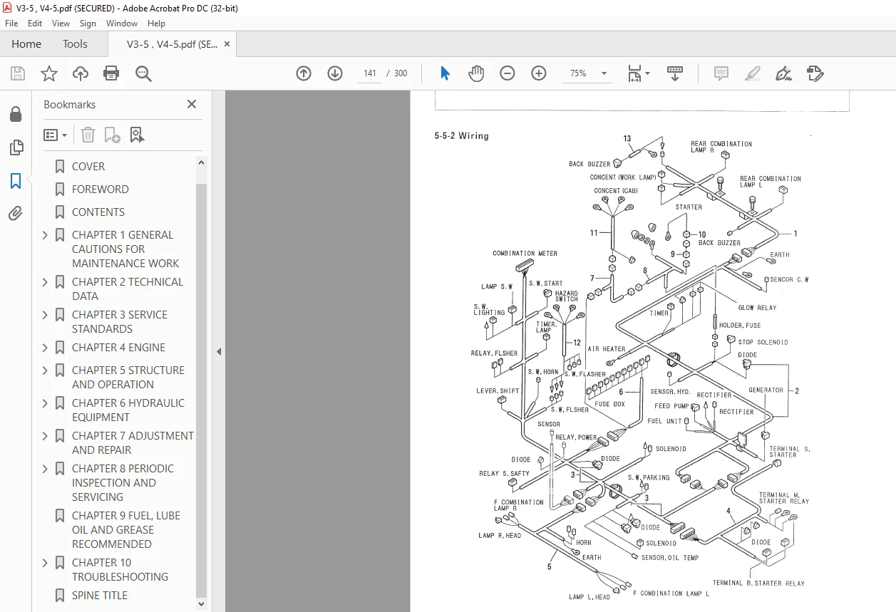
5-5-2 Wiring.....................................................................141
5-5-3 Engine Start/Stop Circuit..................................................141
5-5-4 Charging Circuit...........................................................144
CHAPTER 6 HYDRAULIC EQUIPMENT............................................................145
6-1 Hydraulic Pump (H.S.T.)..........................................................147
6-2 Hydraulic Motor (H.S.T.).........................................................168
6-3 Troubleshooting for Hydraulic Pump and Motor (H.S.T.)...........................181
6-4 Control Valve....................................................................188
6-5 Orbit Roll.......................................................................198
6-6 Hydraulic Cylinders..............................................................218
CHAPTER 7 ADJUSTMENT AND REPAIR..........................................................224
7-1 Machine..........................................................................225
7-1-1 Layout of Electrical Equipment.............................................225
7-1-2 Monitor and Alarm System...................................................227
7-1-3 Engine Controls............................................................230
7-1-4 Fuel Tank & System.........................................................231
7-1-5 Replacement of Tire........................................................232
7-2 Hydraulic Pump (H.S.T.)..........................................................233
7-2-1 Removal and Installation of Hydraulic Pump.................................233
7-3 Front and Rear Axles.............................................................235
7-3-1 Removal and Installation of Front and Rear Axles...........................235
7-3-2 Disassembly and Reassembly of Front and Rear Axles and Associated Parts....237
7-4 Controls.........................................................................258
7-4-1 Adjustment of Accelerator pedal............................................258
7-4-2 Adjustment of Parking Brake................................................259
7-4-3 Adjustment of Inching Brake................................................260
7-4-4 Adjustment of Loader Link Cabie............................................261
7-4-5 Adjustment of Auto Leveler.................................................262
7-5 Adjustment of Pressure...........................................................263
7-5-1 Hydraulic Circuit Diagram..................................................263
7-5-2 Pressure Measurement of Hydraulic Pump (H.S.T.)............................264
7-5-3 Control Valve..............................................................265
7-5-4 Orbit Roll.................................................................266
7-6 Loader Towing at Hydraulic Power Source Failure..................................267
7-7 Cabin ...........................................................................270
7-7-1 Cabin Sevicing Procedure...................................................270
CHAPTER 8 PERIODIC INSPECTION AND SERVICING..............................................284
8-1 List of Periodic Inspection and Servicing........................................285
CHAPTER 9 FUEL, LUBE OIL AND GREASE RECOMMENDED..........................................287
CHAPTER 10 TROUBLESHOOTING...............................................................289
10-1 Troubleshooting.................................................................290
SPINE TITLE..............................................................................300
PLEASE NOTE:
This is the SAME manual used by the dealers to troubleshoot any faults in your vehicle. This can be yours in 2 minutes after the payment is made.
Contact us at [email protected] should you have any queries before your purchase or that you need any other service / repair / parts operators manual.
SK
✹
What Our Customers Say
★★★★★Live reviews from customers
Loading customer reviews...
🌟 Related Products
Discover more professional manuals for your equipment