YANMAR ViO38U EXCAVATOR SERVICE MANUAL – PDF DOWNLOAD
YANMAR VIO38U EXCAVATOR SERVICE MANUAL – PDF DOWNLOAD:
IMAGE PREVIEW:
YANMAR ViO38U EXCAVATOR SERVICE MANUAL – PDF DOWNLOADYANMAR ViO38U EXCAVATOR SERVICE MANUAL – PDF DOWNLOAD
DESCRIPTION:
YANMAR ViO38U EXCAVATOR SERVICE MANUAL – PDF DOWNLOAD
Correct work means the quickest possible completion of according to the correct procedures and the specified standards.
It is important when conducting certain operations always to bear in mind the equipment, tools, gauges, materials, oil and grease, etc. that you must have ready, as well as items to be checked, adjusted, or disassembled, and cautions to watch out for.
(1) Never attempt servicing while engine is running or immediately after stopping operation. (2) Wear work cloths, safety shoes and helmet. (3) Check the equipment and tools before use. Especially, be sure to check the crane, lifting equipment and tools.
(4) When working together with other persons, allocate everyone’s share of job, arrange the signals and act in concert with the other persons. (5) The operation of the crane and slinging work must be performed by qualified persons.
(6) Do not enter or pass under the raised load. (7) Lift and support the massive parts by crane before removing the installation bolts. (8) Disconnect cables from battery before repairing the electric system.
(9) Remove the battery when welding the machine. (1) Check the service record of the machine. (That is, check how many months or hours the machine has been used since the preceding overhaul, what was the trouble then and what parts were replaced.)
(2) Have all servicing tools ready, i.e., tools, measuring devices (which have received periodic maintenance), containers, oil & grease, etc. (3) Have the service literature (operation manual, parts catalog, etc.) ready.
(1) Clean the machine before disassembly. (2) Check and record the condition of the machine before disassembly : • Model, machine number, operation hours • Reasons for repair, history of repair •
Contamination of filters • Fuel and oil condition • Damage to parts, etc. (3) Place alignment marks on the necessary parts to facilitate reassembly. (4) Clean all the removed parts and new replacement parts and put them in order. (5) Use new seals, split pins, etc. for reassembly.
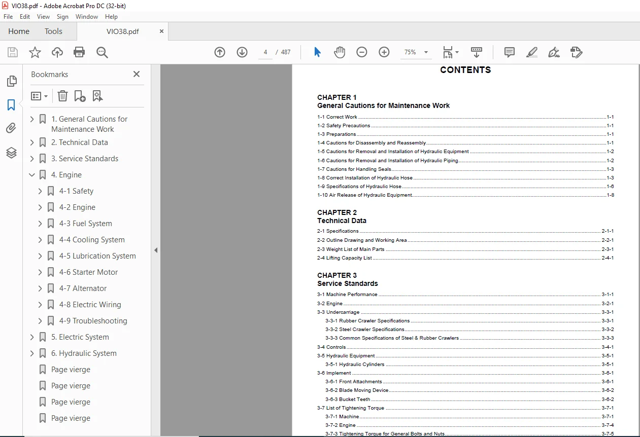
TABLE OF CONTENTS:
YANMAR ViO38U EXCAVATOR SERVICE MANUAL – PDF DOWNLOAD
1. General Cautions for Maintenance Work...............................................  8
	1-1 Correct Work................................................................... 10
	1-2 Safety Precautions............................................................. 10
	1-3 Preparations................................................................... 10
	1-4 Cautions for Disassembly and Reassembly........................................ 10
	1-5 Cautions for Removal and Installation of Hydraulic Equipment................... 11
	1-6 Cautions for Removal and Installation of Hydraulic Piping...................... 11
	1-7 Cautions for Handling Seals.................................................... 12
	1-8 Correct Installation of Hydraulic Hose......................................... 12
	1-9 Specifications of Hydraulic Hose............................................... 15
	1-10 Air Release of Hydraulic Equipment............................................ 17
2. Technical Data...................................................................... 18
	2-1 Specifications................................................................. 20
	2-2 Outline Drawing and Working Area............................................... 27
	2-3 Weight List of Main Parts......................................................  0
	2-4 Lifting Capacity List.......................................................... 29
3. Service Standards................................................................... 32
	3-1 Machine Performance............................................................ 34
	3-2 Engine......................................................................... 38
	3-3 Undercarriage.................................................................. 42
		3-3-1 Rubber Crawler Specifications............................................ 42
		3-3-2 Steel Crawler Specifications............................................. 43
		3-3-3 Common Specifications of Steel & Rubber Crawlers......................... 44
	3-4 Controls....................................................................... 45
	3-5 Hydraulic Equipment............................................................ 46
		3-5-1 Hydraulic Cylinders...................................................... 46
	3-6 Implement...................................................................... 47
		3-6-1 Front Attachments........................................................ 47
		3-6-2 Blade Moving Device...................................................... 48
		3-6-3  Bucket Teeth............................................................ 48
	3-7 List of Tightening Torque...................................................... 49
		3-7-1 Machine.................................................................. 49
		3-7-2 Engine................................................................... 52
		3-7-3 Tightening Torque for General Bolts and Nuts............................. 53
		3-7-4 Hydraulic Fitting........................................................ 54
4. Engine.............................................................................. 56
	4-1 Safety......................................................................... 58
		4-1-1 Safety Statements........................................................ 58
		4-1-2 Safety Precautions....................................................... 59
	4-2 Engine......................................................................... 70
		4-2-1 Before You Begin Servicing............................................... 70
		4-2-2 Special Service Tools.................................................... 71
		4-2-3 Measuring Instruments.................................................... 73
		4-2-4 Cylinder Head............................................................ 75
		4-2-5 Measuring and Adjusting Valve Clearance.................................. 89
		4-2-6 Crankshaft and Camshaft Components....................................... 91
	4-3 Fuel System....................................................................116
		4-3-1 Before You Begin Servicing...............................................116
		4-3-2 Introduction.............................................................117
		4-3-3 Special Service Tools....................................................122
		4-3-4 Measuring Instruments....................................................122
		4-3-5 Fuel System Diagram......................................................123
		4-3-6 Fuel System Components...................................................124
		4-3-7 Fuel Injection Pump .....................................................126
		4-3-8 Checking and Adjusting Fuel Injection Timing.............................137
		4-3-9 Fuel Injectors...........................................................142
	4-4 Cooling System.................................................................148
		4-4-1 Before You Begin Servicing...............................................148
		4-4-2 Introduction.............................................................149
		4-4-3 Cooling System Diagram...................................................149
		4-4-4 Engine Coolant Pump Components...........................................150
		4-4-5 Engine Coolant System Check..............................................151
		4-4-6 Engine Coolant Pump......................................................151
	4-5 Lubrication System.............................................................156
		4-5-1 Before You Begin Servicing...............................................156
		4-5-2 Introduction.............................................................157
		4-5-3 Lubrication System Diagram...............................................159
		4-5-4 Checking Engine Oil Pressure.............................................160
		4-5-5 Trochoid Oil Pump........................................................160
	4-6 Starter Motor..................................................................164
		4-6-1 Before You Begin Servicing...............................................164
		4-6-2 Introduction.............................................................165
		4-6-3 Starter Motor Information................................................165
		4-6-4 Starter Motor Specifications.............................................166
		4-6-5 Starter Motor Troubleshooting............................................167
		4-6-6 Starter Motor Components.................................................168
	4-7 Alternator.....................................................................179
		4-7-1 Before You Begin Servicing...............................................179
		4-7-2 Introduction.............................................................180
		4-7-3 Alternator Specifications................................................180
		4-7-4 Alternator Troubleshooting...............................................181
		4-7-5 Alternator Components....................................................182
		4-7-6 Alternator Wiring Diagram................................................183
		4-7-7 Alternator Standard Output...............................................184
		4-7-8 Alternator...............................................................185
	4-8 Electric Wiring................................................................190
		4-8-1 Electric Wiring Precautions..............................................190
	4-9 Troubleshooting................................................................191
		4-9-1 Special Service Tools....................................................191
		4-9-2 Troubleshooting By Measuring Compression Pressure........................192
		4-9-3 Quick Reference Table For Troubleshooting................................194
5. Electric System.....................................................................200
	5-1 Electric Equipment of Machine..................................................202
		5-1-1 Parts Layout of Electrical Equipment.....................................202
		5-1-2  Monitor and Alarm Systems...............................................205
		5-1-3  Wiring Diagram..........................................................208
		5-1-4  Circuit Description of Engine Start and Stop, and Battery Charging......209
6. Hydraulic System....................................................................212
	6-1 Outline........................................................................214
		6-1-1 Control Valve Operation..................................................216
		6-1-2 Additional Operation of Control Valve....................................217
	6-2 Hydraulic Circuit Schematic....................................................218
	6-3 Circuit Operation..............................................................219
		6-3-1 Boom.....................................................................219
		6-3-2 Arm......................................................................220
		6-3-3 Bucket...................................................................221
		6-3-4 Swing....................................................................222
		6-3-5 Boom Swing...............................................................223
		6-3-6 Blade....................................................................224
		6-3-7 Travel...................................................................225
		6-3-8 Non-Deviation Travel (with Boom, Arm, Bucket or Boom Swing Operation)....226
		6-3-9 Non-Deviation Travel (with Bucket Operation).............................227
		6-3-10 Simultaneous Operation of Boom Up and Arm Retract.......................228
		6-3-11 Simultaneous Operation of Boom Up and Bucket............................229
		6-3-12 Simultaneous Operation of Boom Up and Swing.............................230
		6-3-13 Simultaneous Operation of Arm and Bucket................................231
		6-3-14 Hydraulic P.T.O.........................................................232
Page vierge............................................................................ 31
Page vierge............................................................................ 55
Page vierge............................................................................211
Page vierge............................................................................233
PLEASE NOTE:
This is the SAME exact manual used by your dealers to fix your vehicle.
The same can be yours in the next 2-3 mins as you will be directed to the download page immediately after paying for the manual.
Any queries / doubts regarding your purchase, please feel free to contact [email protected]
SK
✹
What Our Customers Say
★★★★★Live reviews from customers
Loading customer reviews...
🌟 Related Products
Discover more professional manuals for your equipment