Zetor Tractor Forterra CL Operator’s Manual – PDF DOWNLOAD
Original price was: $86.95.$28.95Current price is: $28.95.
Zetor Tractor Forterra CL Operator’s Manual – PDF DOWNLOAD
Description
Zetor Tractor Forterra CL Operator’s Manual – PDF DOWNLOAD
FILE DETAILS:
Zetor Tractor Forterra CL Operator’s Manual – PDF DOWNLOAD
Language : English
Pages : 212
Downloadable : Yes
File Type : PDF
Size: 15.2 MB
DESCRIPTION:
Zetor Tractor Forterra CL Operator’s Manual – PDF DOWNLOAD
ZETOR:
- This Operator’s Manual for the Zetor tractors, which we are presenting to you will help you to
become familiar with the operation and maintenance of your new tractor. - Although many of you have rich experience with the operation of other tractors, please, read the
information contained in this Operator’s Manual very carefully. - In the Manual you will find a lot of new information and get a perfect overview of how to use the
tractor with maximum efficiency during various kinds of work. - If you observe the rules of tractor operation and maintenance and driving safety, your new tractor will
become your reliable and long-term friend.
SAFETY INSTRUCTIONS FOR USERS:
General Safety Regulations:
- The tractor should only be operated by a trained individual who possesses a valid driving license and has a thorough understanding of the operation and safety rules.
- In addition to the safety instructions mentioned in the Operator’s Manual, it is mandatory to comply with the generally applicable safety and traffic rules of the country where the tractor is being used.
Proper Clothing:
- Avoid wearing loose clothing and ensure that long hair is not free-flying.
- Use suitable prescribed personal protective equipment (such as working boots, gloves, goggles, etc.) during all work.
Starting the Engine:
- Start the engine only from the driver’s seat with the clutch pedal fully depressed. It is extremely dangerous to start the engine by short-circuiting the starter terminals.
- Ensure that the key in the switch box is in the “I” position.
- When using an electric heater to heat the engine, connect the power supply cord to the heater first, and then plug it into the electric mains. After heating, disconnect the heater from the electric mains. Be cautious of the risk of electric shock.
- It is forbidden to start the engine while driving the tractor downhill.
- Starting the tractor by towing it with another tractor or vehicle is only permitted when using a pull bar.
Driving Operation:
- Regularly check and immediately replace any hoses in the hydrostatic steering, brakes, and fuel system that show signs of damage, such as cracks, loose connections, or mechanical damage. Replace hoses with indicated service life immediately after the specified period has expired.
- Ensure that the brakes and steering are always in perfect condition.
- When driving on roads with trailers and tools, connect the brake pedals with a latch.
- It is prohibited to drive downhill without engaging a gear.
- Exercise special caution when driving on slopes and on muddy, sandy, icy, or uneven ground.
IMAGES PREVIEW OF THE MANUAL:
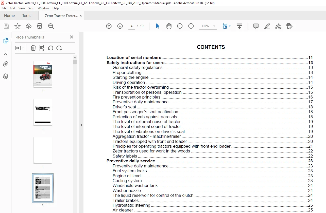
TABLE OF CONTENTS:
Zetor Tractor Forterra CL Operator’s Manual – PDF DOWNLOAD
Location of serial numbers 11
Safety instructions for users 13
General safety regulations 13
Proper clothing 13
Starting the engine 14
Driving operation 14
Risk of the tractor overturning 15
Transportation of persons, operation 15
Fire prevention principles 16
Preventive daily maintenance 17
Driver’s seat 18
Front passenger´s seat notification 18
Protection of cab against aerosols 18
The level of external noise of tractor 19
The level of internal sound of tractor 19
The level of vibrations on driver´s seat 19
Aggregation tractor – machine/trailer 20
Tractors equipped with front end loader 20
Principles for operating tractors equipped with front end loader 21
Zetor tractors used for work in the woods 22
Safety labels 22
Preventive daily service 23
Preventive daily maintenance 23
Fuel system leaks 23
Engine oil level 23
Cooling system 23
Windshield washer tank 24
Washer nozzle 24
The liquid reservoir for control of the clutch 24
Trailer brakes 24
Hydrostatic steering 25
Air cleaner 25
Cab filtration 25
Hitches 25
Inspection of fouling of coolers 26
After work with front implements and in case of cooler clogging 26
Tyres and wheels 26
Short functional test 26
Acquaintance with tractor 27
Safety cabin 27
Opening the door from the outside 27
Opening the door from the inside 27
Rear window 28
Side window 28
Emergency exits 28
Hinged lid 28
Adjustable screen and cover of the swing lid 29
Shelf 29
Rear view mirrors 30
Internal lighting 30
Aggregation opening 30
Driver’s seat Sears 31
Passenger´s seat 31
Tilting and protrusion of steering wheel 32
Control panel on the right column of the cabin 32
Windscreen wiper 32
Front wiper speed switch 33
Rear window wiper 33
Windscreen washer 33
Upper working lights switching on 34
Control panel on the right rear mudguard 34
Panel of the instrument panel 35
Lights switch 35
CONTENTS
3
Lights switch between the grill and the cabin 35
Direction lights, lower beam head lights, head lights and horn switches 36
Switch box 37
Switch box key in the position (0) 37
Switch box key in the position (I) 37
Switch box key in the position (II) 37
Manual throttle 38
Pedals and levers 38
Gear shifting lever 38
Reversing lever 39
Road and reduced speeds shifting lever 39
PTO revolutions preselection lever 39
Auxiliary hydraulic switchbox control (external hydraulic circuit) 39
Manual brake lever and coupling for semi-trailer control lever 40
Battery disconnector 40
Heating control panel, * air-condition 41
Heating valve control (A) 41
Switch air-condition (C) 41
Air circulation in cabin control (D) 42
Proper function of the heating and air-condition system 42
Fast heating of the cabin area 42
Fast cooling of the space of the cabin 42
Immediately after cooling the cabin 43
Operation of heating or air-condition with tractor´s work 43
Air-condition and heating registers (A) 43
Front windshield (B) defrosting 44
*Air filter with active carbon 44
Fuel tank 45
Fuel tank drain plug 45
Urea tank 45
Instrument panel 47
Instrument panel – signal lamps 47
Instrument panel – instruments 48
Instrument panel – buttons 48
Display description 49
Display – change of display 49
Display – display of air pressure in the air-pressure system of the tractor 52
Display – warning of low air pressure in the air-pressure system of the tractor 52
Display – resetting data 53
Display – manual brake 53
Display – service menu 53
Service menu 53
Display – indicator of service inspection intervals 54
Exceeding the service interval 54
Zeroing (reset) of the indicator of service inspection intervals 54
Error signalling 55
Display – error messages 55
Description of the display of error messages 56
Symbols of tractor nodes 56
Display – history of defects 56
Display – setting language mutation 57
Display – backlight of display 57
Display – setting of day and night backlight of the display 58
Display – setting the automatic mode of the display backlight 59
Display – setting and calibration 60
Travel speed calibration 61
Display – machined area 62
Machined area menu 62
Processed area – user selection 63
The processed area – setting of the width of aggregation 63
Machined area record 64
System of treatment of exhaust gases – setting 65
Instrument panel – warning 65
CONTENTS
4
Replenish fuel 65
Add urea 65
High temperature of the cooling liquid 66
Signalling of driver’s seat 66
System of additional treatment of exhaust gases 67
Conditions for DPF operation 68
Error signalling of DPF system 69
Conditions for SCR system operation 69
Urea (Aqueous Urea Solution AUS 32, DEF) 70
Principles for safe handling of urea (AUS 32, DEF) 70
Error signalling of SCR system 71
Indication of DPF and SCR errors on the display of the instrument panel 71
Indication of amount of urea in the tank 72
Reduction of the engine power and engine revolutions 73
Signalling of whether DPF is full 74
Long-term shutdown of tractor 74
Repairs and maintenance of the system of additional treatment of exhaust gases 74
System of treatment of exhaust gases – setting 75
Automatic regeneration of the diesel particulate filter – REGEN AUTO 75
Inhibition of regeneration of the diesel particulate filter – REGEN INHIBIT 76
Driving operation 77
Starting the engine 77
Non-permitted starting 77
If you do not succeed in starting the engine 78
Ignition system failure signalization 78
*Coolant heater 78
Starting the engine while using coolant heater 79
Immediately after start 79
Engine heating 79
Error signalling 80
Indication of the limitation of the engine power and engine revolutions 80
Signalling errors in the system of additional treatment of exhaust gases 81
Diesel particle filter 81
Filter of solid particles – indication of operation and failures of the system 82
Diesel particle filter regeneration 83
Gear shifting 84
Gear shifting from lower to higher gears 84
Gear shifting from higher to lower gears 84
Recommendation for gear shift 84
Reversing lever 85
Shifting road and reduced speeds 85
Three-gear torque multiplier 86
Signalization of multiplier function 86
Increasing, decreasing the travel speed by two gears 86
Multiplier preselection switch 87
Automatic multiplier shifting 87
Front drive axle control 89
Driving with engaged front axle drive 89
Front Drive Axle Control – Manual Mode 89
Automatically disconnect the front axle – manual mode 90
Front Drive Axle Control – Automatic Mode 90
Automatic front axle control mode 90
Differential lock control 91
Differential lock control – automatic mode 91
Automatic mode of differential lock control 92
Drive away 92
Manual brake – signalization 93
Driving up the slope 93
Driving down the slope 93
Foot brakes 93
Emergency braking 94
Brakes of trailers and semi-trailers 94
Connection of the ABS system of the trailer or semi-trailer 94
CONTENTS
5
The button for temporary deactivation of brakes of the trailer or semi-trailer 95
Air brakes of trailers and articulated trailers 95
Warning signalization of air pressured drop 96
One-hose and two-hose brakes 96
One-hose brakes 96
Two-hose brakes 96
Hydraulic brakes of trailers 97
Connecting and disconnecting quick couplings of trailer hydraulic brakes 97
The socket for connection of the electrical installation of the trailer or semi-trailer 97
Stopping the tractor – manual brake 98
Stopping the engine 98
Leaving the tractor 98
Warning signalization of hydrostatic steering failure 99
Important warnings 99
Running in the tractor 101
General principles of new tractor run-in in first 100 hours of operation 101
In first 10 hours of operation 101
From 100 hours of operation 101
Transport use 103
Front hook 103
Height adjustment and disassembly of the CBM stage hitch 103
Automatic mouth of the CBM stage hitch 104
Swing drawbar 104
Modular system of hitches for trailers and semi-trailers 104
Swinging draw-bar console module 104
Swinging draw-bar console with a fixed pin module 105
Console with a ø 80 ball module 105
Hitch for a single-axle CBM semi-trailer 105
Uncoupling of a single-axle trailer 105
Coupling of a single-axle trailer 106
Maximum permissible vertical static load of hitches for trailers and semi-trailers 106
Drive of farming machines 107
Work with PTO shaft 107
Display of revolutions of PTO shafts 107
Replaceable end points of rear PTO shaft 107
Control elements of PTO shafts 108
The buttons for activation of PTO shafts 108
Selection switch of rear PTO clutch revolutions (P T O ) 108
Rear PTO shaft revolutions preselection lever 109
Standard and economical independent revolutions of rear PTO shaft 110
Dependent and independent rear PTO shaft revolutions 110
Automatic disengagement of PTO clutch 111
Setting automatic disengagement of PTO shaft clutch – display description 111
Automatic disengagement of PTO shaft clutch – return to basic setting 111
Work with automatic disengagement of PTO shaft clutch 112
Facilitating connection of joint shaft of an aggregated machine to the tractor 113
Working modes of PTO shafts 113
Activation of the rear PTO shaft – independent revolutions – common working mode 114
Activation of the rear PTO shaft – independent revolutions – stationary working mode 115
Deactivation of the rear PTO shaft – independent revolutions 116
Rear PTO shaft switch – dependent speed – ordinary mode of operation 117
Rear PTO shaft switch – dependent speed – stationary mode of operation 118
Front PTO shaft 120
Activation of the front PTO shaft – common working mode 120
Activation of the front PTO shaft – stationary working mode 121
Deactivation of the front PTO shaft 121
Maximum transferred output 122
Drive of machines with greater inertia masses 122
Hydraulic system 123
Hydraulic system 123
Hydraulic pump 123
Control elements placement 123
Outer hydraulic circuit 123
CONTENTS
6
Connecting and disconnecting quick-couplers 123
Quick-couplings with drip collection 123
Amount of oil taken from outer hydraulic drives 124
Hydraulic distributor of the outer hydraulic circuit 124
Description of the functions of individual positions of control levers of the hydraulic distributor 125
Rear outlets of the outer hydraulic circuit 125
Front outlets of the outer hydraulic circuit 126
Connecting machines and implements to the outer hydraulic circuit 126
Electro-hydraulic system 127
Control element functions 127
Equipment ‘OFF’ 127
Blocking cancellation 128
Quick sinking 128
Transport of implements 129
Stop position 129
Vibration compensator (damper) 129
Limitation of the upper position of the three-point hitch 130
Lowering speed 130
Free position 130
Setting the control of three-point hitch 130
Manual setting of control of three-point hitch 131
Automatic control of three-point hitch 131
Using the rear control 132
External control buttons of the electro-hydraulic system 132
Indication of EHR-B errors 133
Description of signals of EHR-B electro-hydraulic system errors 133
Description of minor errors of the EHR-B electro-hydraulic system 134
Hitches 135
Rear three-point hitch 135
Safety principles of working with the three-point hitch 136
Height adjustment of the lifting draw-bars 136
Fixed and free position of the lower hydraulic draw-bars 136
Limiting draw-bars 136
*Lower draw bar with slipping out end pieces 137
*Lower draw bar with CBM hooks 137
Securing lower draw bars with CBM hooks 137
Upper draw-bar 137
*Front three-point hitch 138
Controlling front three-point hitch 138
Adjusting the lowering rate of the front three-point hitch 138
Hydraulic lock of the front three-point hitch 138
Working and transport position of the front three-point hitch 139
Driving with agricultural machines attached to the front three-point hitch 139
Wheel track change 141
Gauges of the front wheels of the front drive axle of the tractors equipped with screwed footer discs 141
Possible adjustable tracks of the front wheels of the front driving axle of the tractors 141
Front wheels track of front drive axle in tractors equipped with non-removable discs 142
Toe-in of the wheels of the front driving axle 143
Adjustment of toe-in of the wheels of the front driving axle 143
Front drive axle fenders 144
Setting wheel stops with front drive axle 144
Rear wheels wheel track 145
Gauges of the tractor rear wheels equipped with screwed footer discs 145
Rear wheel track change 145
The gauges of the tractor rear wheels equipped with solid discs 146
Ballast weights 147
*Rear wheel weights 147
Bottom weights 147
*Front weights 147
*Weight of the front three-point hitch 148
Valve for filling tyre tubes with liquid 148
Procedure of filling the tyres with liquid 148
Procedure of draining liquid from the tyres 149
CONTENTS
7
Wedging the front wheels 149
Antifreeze solution for tyre filling 150
Electric installation 151
Basic service information 151
Accumulator battery 151
Battery disconnector 152
Accumulator battery maintenance 153
Alternator 154
Alternator maintenance 154
Electric installation overload 154
Fuse panels 155
Checking the adjustment of the front grill headlights 159
Adjusting the front grill headlights 159
Checking the adjustment of the cab roof headlights 160
List of lamps 160
Tractor maintenance 161
Service inspections 161
Steps performed daily before the start of work 161
Steps performed every 50 hours of work 161
Steps performed every 100 hours of work 161
Steps performed every 500 hours of work 161
Steps performed outside the interval of 500 hours of work 162
Monthly performed actions 162
Filling and filter replacement 163
Used operation liquids and filling – quantities 164
ZETOR service fillings 164
Motor oils 164
Oil in the gearbox and final drivehousing 164
Oil for the front driving axle 164
Specification of oils for Zetor engines equipped by diesel particle filter 164
Specification of oil for tractor transmission devices 164
Specification of oil for the front driving axle 164
Other recommended service fillings tested on Zetor tractors 165
Oils for Zetor engines which are equipped with diesel particle filter 165
Oils for tractor transmission gearing 165
Oil for the front driving axle 165
Front PTO oil 166
Plastic lubricant for the tractor 166
Liquid for control of the travel clutch 167
Fuel for Zetor engines which are equipped with diesel paricle filter 167
Urea (urea solution AUS 32) 167
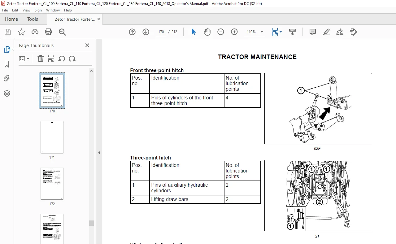
Tractor greasing scheme 168
Safety instructions for lubrication of the tractor 168
Solid front drive axle 168
Hitch for a single-axle semi-trailer 168
Front three-point hitch 169
Three-point hitch 169
Hitch mouth for a trailer 169
Reversion lever pin 169
Technical maintenance of the tractors after a general overhaul of the main groups 169
Maintenance instructions 171
Opening the hood 171
Checking the oil level in the engine 171
Draining oil from the engine 172
Filling the engine with oil 172
Replacement of carter exhaust oil separator filter element 172
Replacing the fuel filter element 173
Bleeding the fuel system 173
Dry air cleaner maintenance instructions 174
Air cleaner disassembly 174
Recovery of the mainair cleaner element 174
Replacing the safety element of the air cleaner 174
Reassembly of the air cleaner elements 175
CONTENTS
8
Bleeding the hydraulic circuit of the hydrostatic steering 176
Replacing the hydrostatic steering hoses 176
Replacing coolant 177
Check and replacement of oil in gear box 178
Draining and checking holes 178
Checking the oil in gearbox 178
After draining oil 178
Replacement of the transmission oil cleaner element with hydraulic pump suction filter 179
Insertion piece replacement of the oil cleaner with delivery filter of the gearbox switchboard 179
Filling, controlling and draining hole of oil of front drive axle 179
Filling, controlling and draining hole of oil of front wheels reducers 179
Front PTO 180
Addition of the liquid for control of the clutch 180
Carbon filter installation instructions 180
Cleaning the heating filters 181
Air filter with active carbon 181
Air-conditioning maintenance 182
Draining condensate from the air reservoir 182
Checking the air systems for leaks 183
Working pressure of air brakes 183
Maintenance and treatment of tyres 183
Recommended inflation values of the front wheel tyres 184
Tyres for driving wheels 184
Storing the tractor 185
Diesel particle filter maintenance 185
Adjustment 187
Adjusting valve clearance 187
Flat belt drive tension of accessories 187
Bleeding the brake system of the tractor 187
Adjustment of free travel of clutch pedal 187
Bleeding of hydraulic clutch circuit 188
Foot brake check 188
Foot brake adjustment 189
Parking brake adjustment 189
Adjustment of the lifting draw-bars of the hitch for a single-axle semi-trailer 189
Adjusting the bowden cable 189
Main technical parameters 191
Main tractor’s parameters (mm) 191
Technical data of engines 192
Permitted maximum load of front axle (kg) 193
Permitted maximum load of rear axle (kg) 193
Permitted maximum weight of set ‘tractor + mounted machine’ (kg) 193
Manoeuvrability condition 193
Front tires steerability 194
Change of the load-bearing capacity of the front tyres (%) 194
Bearing capacity of rear tires 195
Change of the load capacity of the rear tyres (%) 196
Permitted combinations of wheels for tractors 196
Power 197
Lifting force of the three-point hitch 197
Tensile force 197
Tractor speeds (40 km/h) 198
Forward speed 198
Reverse speed 199
Independant rear PTO shaft revolutions 199
Dependent PTO shaft revolutions with nominal engine revolutions 200
Speed of the Zuidberg front PTO 201
The outer contour and the turning circle diameter of the tractor 201
Calculation of tractor load limit 202
Index 205
Customer Support: [email protected]
PLEASE NOTE:
- This is the SAME manual used by the dealers to troubleshoot any faults in your vehicle. This can be yours in 2 minutes after the payment is made.
- Contact us at [email protected] should you have any queries before your purchase or that you need any other service / repair / parts operators manual.
S.V