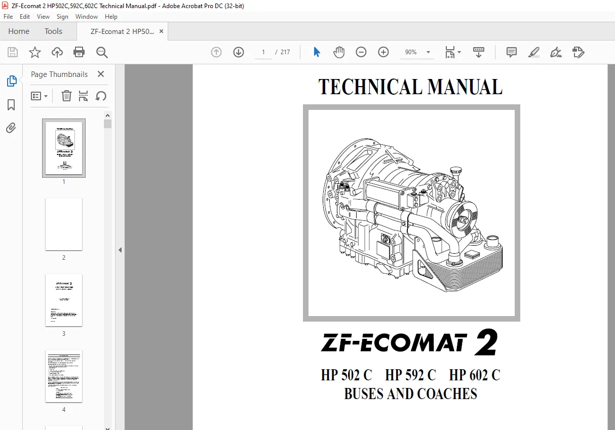
ZF-Ecomat 2 HP 502 C HP 592 C HP 602 C Buses & Coaches Technical Manual 4149765101a – PDF DOWNLOAD
$28.95
ZF-Ecomat 2 HP 502 C HP 592 C HP 602 C Buses & Coaches Technical Manual 4149765101a – PDF DOWNLOAD
Description
ZF-Ecomat 2 HP 502 C HP 592 C HP 602 C Buses & Coaches Technical Manual 4149765101a – PDF DOWNLOAD
FILE DETAILS:
ZF-Ecomat 2 HP 502 C HP 592 C HP 602 C Buses & Coaches Technical Manual 4149765101a – PDF DOWNLOAD
Language : English
Pages : 217
Downloadable : Yes
File Type : PDF
IMAGES PREVIEW OF THE MANUAL:
DESCRIPTION:
ZF-Ecomat 2 HP 502 C HP 592 C HP 602 C Buses & Coaches Technical Manual 4149765101a – PDF DOWNLOAD
IMPORTANT NOTICE:
- This Ecomat Technical Manual provides a technical basis for the Ecomat 2 system and has been produced for the
benefit of vehicle and coachwork manufacturers as well as ZF employees. - This manual contains answers to questions ranging from specifications to installation inspection and
commissioning. - This manual provides the basis for specifications of the transmission and peripheral units.
Optimum procedure leading up to series production delivery:
• Specification of transmission, electronic automatic gear change and peripheral units performed by vehicle
manufacturer and ZF using the “Form for parts list preparation”
• Documentation by ZF
• Initial installation
• Initial installation inspection performed by ZF personnel
• Commissioning performed by ZF personnel
• Certificate of Release granted by ZF
• Correction work if required by Certificate of Release
- ZF can bear responsibility for any errors in the initial installation only if sign-off has been performed by
authorised ZF personnel and if all defects found by ZF have been rectified by the vehicle or bodywork
manufacturer. The vehicle or bodywork manufacturer shall bear sole responsibility for any damage caused
by defects attributable to the vehicle or coachwork manufacturer which could not be detected by ZF
personnel during initial sign-off. - If you require additional information concerning installation and the installation inspection, we have prepared an
“Installation Guidelines” manual in addition to the Ecomat technical manual. When installing the transmission,
these installation guidelines must be observed.
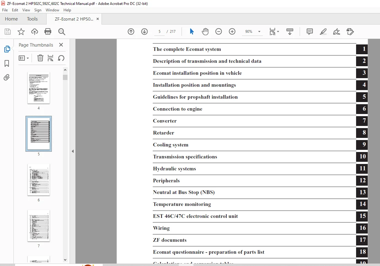
TABLE OF CONTENTS:
ZF-Ecomat 2 HP 502 C HP 592 C HP 602 C Buses & Coaches Technical Manual 4149765101a – PDF DOWNLOAD
Technical Manual ECOMAT 2........................................................................................................................  1
	Important notice.............................................................................................................................  4
	Survey of chapters...........................................................................................................................  5
	Table of contents............................................................................................................................  6
	1 Ecomat system solution..................................................................................................................... 11
	2 Description of transmission and technical data ............................................................................................ 13
		2.1 Brief description of transmission.................................................................................................... 13
		2.2 Transmission structure and auxiliaries............................................................................................... 15
		2.3 Transmission ratios and powerflow diagram............................................................................................ 17
		2.4 Maximum engine torques and vehicle weights........................................................................................... 19
		2.5 Torsional vibration in driveline – inertia torques – vibration substitution model.................................................... 20
		2.6 Weights and inertia torque values.................................................................................................... 26
			2.6.1 Coaxial output without heat exchanger J08...................................................................................... 26
			2.6.2 Coaxial output with heat exchanger J01......................................................................................... 27
			2.6.3 Coaxial output with heat exchanger J05......................................................................................... 28
			2.6.4 Coaxial output with heat exchanger J10......................................................................................... 29
			2.6.5 Angle drive 80º without offset, with heat exchanger J05........................................................................ 30
			2.6.6 Angle drive 80º without offset, with heat exchanger J10........................................................................ 31
			2.6.7 Angle drive 80º RHD (with right offset), with heat exchanger J05............................................................... 32
			2.6.8 Angle drive 80º RHD (with right offset), without heat exchanger J08............................................................ 33
			2.6.9 Angle drive 80º LHD (with left offset), with heat exchanger J10................................................................ 34
			2.6.10 Angle drive 80º LHD (with left offset), without heat exchanger J08............................................................ 35
		2.7 Clutch combinations.................................................................................................................. 36
	3 Ecomat installation position in vehicle.................................................................................................... 37
	4 Installation position and mountings........................................................................................................ 39
		4.1 Transmission flange-mounted on engine................................................................................................ 39
		4.2 Engine and transmission installed separately......................................................................................... 40
	5 Guidelines for propshaft attachment........................................................................................................ 41
		5.1 Permissible rotational irregularity.................................................................................................. 41
		5.2 Permitted resultant deflection angle for each joint.................................................................................. 42
		5.3 The permitted resultant flexure angle for all joints................................................................................. 43
		5.4 Single-section propshafts............................................................................................................ 44
		5.5 Multi-section propshafts............................................................................................................. 44
		5.6 Maximum permissible propshaft length................................................................................................. 45
	6 Connection to engine....................................................................................................................... 47
		6.1 ZF equipment supplied................................................................................................................ 49
		6.2 Engine connection study.............................................................................................................. 49
		6.3 Engine connection - additional information........................................................................................... 49
		6.4 Engine connection drawing............................................................................................................ 50
	7 Converter.................................................................................................................................. 53
		7.1 Description of torque converter...................................................................................................... 53
		7.2 How the torque converter works....................................................................................................... 53
		7.3 Getting the right torque converter for your engine................................................................................... 54
		7.4 Torque converter graph............................................................................................................... 55
		7.5 Torque converter-basic curves........................................................................................................ 57
			W360*TPC145*MUE2.22.................................................................................................................. 57
			W360*TPC210*MUE2.43.................................................................................................................. 58
			W360*TPC210*MUE2.43.................................................................................................................. 59
			W360*TPC210*MUE2.43.................................................................................................................. 60
			W360*TPC210*MUE2.43.................................................................................................................. 61
			W360*TPC210*MUE2.43.................................................................................................................. 62
			W360*TPC210*MUE2.43.................................................................................................................. 63
			W360*TPC210*MUE2.43.................................................................................................................. 64
			W360*TPC210*MUE2.43.................................................................................................................. 65
	8 Retarder................................................................................................................................... 67
		8.1 Structure and function of retarder................................................................................................... 68
		8.2 Retarder action...................................................................................................................... 68
		8.3 Retarder control device.............................................................................................................. 69
		8.4 Retarder and engine brake............................................................................................................ 71
		8.5 Retarder activation variants......................................................................................................... 72
			Retarder activation variants/diagram................................................................................................. 73
	9 Cooling system............................................................................................................................. 75
		9.1 Choice of oil cooler................................................................................................................. 75
			9.1.1 Approval criteria for temperature measurements................................................................................. 75
			9.1.2 Approval criteria for service routes with system under feedback control........................................................ 75
			9.1.3 Limit values for oil temperature............................................................................................... 75
			9.1.4 Cooling system with retarder................................................................................................... 76
			9.1.5 Cooling system without retarder................................................................................................ 76
		9.2 Position of oil cooler............................................................................................................... 77
		9.3 Cooler fitted on transmission........................................................................................................ 77
		9.4 Layout with oil cooler separate from transmission.................................................................................... 77
			9.4.1 Oil line connections........................................................................................................... 77
			9.4.2 Installation guidelines........................................................................................................ 77
		9.5 Cooling water circuit................................................................................................................ 78
		9.6 Oil cooler specification............................................................................................................. 81
			9.6.1 Design requirements - extract of key data...................................................................................... 81
			9.6.2 Technical inspections.......................................................................................................... 81
			9.6.3 Technical supply conditions.................................................................................................... 82
		9.7 Required performance of cooling water and antifreeze................................................................................. 82
			9.7.1 General........................................................................................................................ 82
			9.7.2 Fresh water.................................................................................................................... 82
			9.7.3 Antifreeze..................................................................................................................... 82
			9.7.4 Cooling water.................................................................................................................. 82
		9.8 Example of calculation............................................................................................................... 83
		9.9 Temperature measurements in bus...................................................................................................... 84
			9.9.1 Measurement conditions......................................................................................................... 84
			9.9.2 Temperature measurements....................................................................................................... 84
			9.9.3 Approval criteria for temperature measurements................................................................................. 85
			9.9.4 Temperature measurement points................................................................................................. 86
				Position of temperature measuring points......................................................................................... 87
	10 Transmission specifications............................................................................................................... 89
		10.1 < L ... > Installation position..................................................................................................... 90
			10.1.1 Flange-mounted installation position < L 01 >................................................................................. 91
			10.1.2 Separate installation position < L 02 >....................................................................................... 92
			10.1.3 Input flange.................................................................................................................. 93
		10.2 < J > Heat exchanger arrangement.................................................................................................... 95
			10.2.1 < J 01/1 > Coaxial output, heat exchanger at rear, accumulator horizontal on left............................................. 96
				      < J 01/2 > Coaxial output, heat exchanger at rear, accumulator rear transverse............................................. 97
			10.2.2 < J 05/1 > Coaxial or 80º RHD output (with axial offset), heat exchanger vertical on left, accumulator horiz. on left......... 98
				      < J 05/2 > 80º to left of angle drive (w/o axial offset),  heat exchanger horizontal on left, accumulator horizontal on.... 99
			10.2.3 < J 10/1 > Coaxial output, heat exchanger vertical on right, accumulator horizontal on left...................................100
				      < J 10/2 > Coaxial output, heat exchanger vertical on right, accumulator rear transverse...................................101
			10.2.4 < J 08 > Coaxial output, heat exchanger separate from transmission, accumulator direct mounting...............................102
				                     Threaded cooler connecting piece............................................................................103
		10.3 < F ... > Oil sump..................................................................................................................105
			10.3.1 Deep oil sump < F 02 >........................................................................................................106
			10.3.2 Deep oil sump < F 04 >; left and right-hand connection prepared...............................................................107
			10.3.3 Flat oil pan < F 01 >.........................................................................................................108
			10.3.4 Flat oil pan < F 05 >; left and right-hand connection prepared................................................................109
		10.4 < K ... > Oil filling...............................................................................................................110
			10.4.1 Oil filling < K 01 >..........................................................................................................111
			10.4.2 Oil filling  < K 02 >; < K 04 >; < K 05 >.....................................................................................112
			10.4.3 Oil filling  < K 03 >; < K 06 >...............................................................................................113
			10.4.4 Oil filling < K 09 >..........................................................................................................114
			10.4.5 Oil filling  < K 10 >.........................................................................................................115
			10.4.6 Transmission with lateral oil filling oil level marks - Oil filling 4139 500 734 (c)..........................................116
				Oil filling 4139 500 901 USA version.............................................................................................118
		10.5 Electrical oil level check..........................................................................................................120
		10.6 < A ... > Transmission output.......................................................................................................121
			10.6.1 Coaxial output < A 01 >.......................................................................................................122
			10.6.2 80 º angle drives.............................................................................................................123
			10.6.3 < A 11 > 80 º LHD output flange (with axial offset)...........................................................................124
			10.6.4 Ecomat output flange; coaxial and 80º angle drive RHD with offset.............................................................125
	11 Hydraulic circuit diagrams (4149 700 026, pages 1 and 2)..................................................................................127
		11.1 Description of hydraulic system circuit.............................................................................................128
		11.2 Hydraulic diagram, page 1 (without NBS).............................................................................................129
		11.3 Hydraulic diagram, page 2 (with NBS)................................................................................................130
	12 Peripherals...............................................................................................................................133
		12.1 Speed range selection system........................................................................................................134
		12.2 Program change-over switch S5.......................................................................................................137
		12.3 Temperature sensor A6...............................................................................................................137
		12.4 Temperature gauge A5................................................................................................................138
		12.5 Kickdown switch.....................................................................................................................139
			12.5.1 S1 kickdown switch (strong holding force).....................................................................................139
			12.5.2 S1 kickdown switch (low holding force)........................................................................................139
		12.6 Pressure switch S7 - Neutral at Bus Stop (NBS)......................................................................................140
		12.7 Changeover contact and relay........................................................................................................141
	13 Neutral at Bus Stop (NBS).................................................................................................................143
		13.1 Description.........................................................................................................................143
		13.2 Connection diagram..................................................................................................................144
		13.3 Bus stop neutral (NBS) Limited use..................................................................................................145
	14 Temperature monitoring....................................................................................................................147
		14.1 Temperature info via CAN............................................................................................................147
		14.2 Temperature info via temperature sensor A6..........................................................................................147
		14.3 Temperature warning.................................................................................................................147
			14.3.1 Temperature warning via CAN...................................................................................................147
			14.3.2 Temperature warning via warning lamp H3 (pin 53) .............................................................................147
		14.4 Temperature sensor A6...............................................................................................................148
		14.5 Temperature gauge A5................................................................................................................149
		14.6 Resistance characteristics curve temperature sensor.................................................................................150
	15 Electronic automatic control system EST 46 C / 47 C.......................................................................................151
		15.1 Description of function.............................................................................................................152
		15.2 Intended standard functions.........................................................................................................152
		15.3 Functions available on request......................................................................................................153
		15.4 Installation requirements...........................................................................................................153
		15.5 EST 46 C / 47 C technical data......................................................................................................154
		15.6 Installation drawings...............................................................................................................155
			15.6.1 Installation drawing EST 46 C.................................................................................................155
			15.6.2 Installation drawing EST 47 C.................................................................................................156
		15.7 EST 46 C / EST 47 C circuit diagram.................................................................................................157
		15.8 Pin patterns / connection diagrams..................................................................................................158
			15.8.1 Pin patterns..................................................................................................................158
			15.8.2 EST 46 C connection diagram, page 1...........................................................................................159
				     EST 46 C connection diagram, page 2.........................................................................................160
			15.8.3 EST 47 C connection diagram, page 1...........................................................................................161
				      EST 47 C connection diagram, page 2........................................................................................162
		15.9 EST 46 C / 47 C funct. descr. (circuit diagr. 6029 729 040, connect. diagr. 6029 729 041, pin patterns 6029 729 072)................163
		15.10 EST 46 C / 47 C diagnosis systems..................................................................................................170
			15.10.1 MOBiDIG 200 (Plug-In 6008 203 058)...........................................................................................170
			15.10.2 Testman......................................................................................................................171
			15.10.3 Level converter DPA 04 I.....................................................................................................171
			15.10.4 Flash code output via L line.................................................................................................172
		15.11 HST 46 auxiliary control unit......................................................................................................174
			15.11.1 Operating instructions for the HST 46........................................................................................174
			15.11.2 HST 46 technical data........................................................................................................174
			15.11.3 Dimensions of HST 46.........................................................................................................175
		15.12 EST 46 C / 47 C block diagram......................................................................................................176
	16 Wiring....................................................................................................................................177
		16.1 Complete wiring - standard..........................................................................................................177
			16.1.1 Complete cable harness EST 46 C, order drawing................................................................................181
			16.1.2 Complete cable harness EST 47 C, order drawing................................................................................182
		16.2 Complete wiring - with junctions....................................................................................................177
		16.3 Cable connection....................................................................................................................177
		16.4 Wiring specifications...............................................................................................................178
	17 ZF documents..............................................................................................................................183
		17.1 Components..........................................................................................................................183
		17.2 Identification and engine compatibility data........................................................................................184
	18 Ecomat 2 - Parts Lists Questionnaire......................................................................................................185
		VEHICLE DATA.............................................................................................................................185
		ENGINE...................................................................................................................................186
		PERFORMANCE CALCULATION..................................................................................................................186
		COOLING SYSTEM...........................................................................................................................187
		TRANSMISSION VERSION.....................................................................................................................189
		PERIPHERAL COMPONENTS....................................................................................................................192
		ELECTRONIC CONTROL UNIT..................................................................................................................194
			SIGNALS SPECIFICATION (STEP 1).......................................................................................................195
			DIGITAL INPUTS AND OUTPUTS (which can not be realized via CAN).......................................................................198
	19 Calculations and conversion tables........................................................................................................199
		19.1 Selection of driveline components...................................................................................................199
		19.2 Collective formulas for retarder and cooler.........................................................................................200
		19.3 Conversion tables...................................................................................................................201
			19.3.1 Units of length...............................................................................................................201
			19.3.2 Units of area.................................................................................................................201
			19.3.3 Units of volume...............................................................................................................202
			19.3.4 Units of energy...............................................................................................................202
			19.3.5 Units of mass.................................................................................................................203
			19.3.6 Units of force................................................................................................................204
			19.3.7 Units of power................................................................................................................205
			19.3.8 Temperature conversions.......................................................................................................205
			19.3.9 Moment of inertia conversion factors..........................................................................................206
		19.4Torque...............................................................................................................................206
		19.5 List of dynamic tyre radii (Michelin)...............................................................................................206
	20 Oil grades, oil filters...................................................................................................................207
		20.1 List of lubricants TE-ML 14.........................................................................................................209
		20.2 Purity of medium....................................................................................................................216
		20.3 Oil filter..........................................................................................................................216
Questions? Email us: [email protected]
PLEASE NOTE:
- This is not a physical manual but a digital manual – meaning no physical copy will be couriered to you. The manual can be yours in the next 2 mins as once you make the payment, you will be directed to the download page IMMEDIATELY.
- This is the same manual used by the dealers inorder to diagnose your vehicle of its faults.
- Require some other service manual or have any queries: please WRITE to us at [email protected]
S.V