ZF-ECOMAT 2 HP 502 HP 552 HP 592 HP 602 Stage 3 Repair Manual 4149751604 – PDF DOWNLOAD
$28.95
ZF-ECOMAT 2 HP 502 HP 552 HP 592 HP 602 Stage 3 Repair Manual 4149751604 – PDF DOWNLOAD
Description
ZF-ECOMAT 2 HP 502 HP 552 HP 592 HP 602 Stage 3 Repair Manual 4149751604 – PDF DOWNLOAD
FILE DETAILS:
ZF-ECOMAT 2 HP 502 HP 552 HP 592 HP 602 Stage 3 Repair Manual 4149751604 – PDF DOWNLOAD
Language : English
Pages : 334
Downloadable : Yes
File Type : PDF
IMAGES PREVIEW OF THE MANUAL:
DESCRIPTION:
ZF-ECOMAT 2 HP 502 HP 552 HP 592 HP 602 Stage 3 Repair Manual 4149751604 – PDF DOWNLOAD
PREFACE:
This manual is intended for skilled personnel who have been trained by ZF Friedrichshafen AG to
carry out maintenance and repair work on ZF products.
- This manual deals with the standard ZF product in accordance with the state of development on the
date of issue. - However, due to continuing development of the product, repair work might require work practices and
test or adjustment data which are not contained in this manual. We therefore recommend that work
done on your ZF product is carried out only by skilled mechanics who have had their practical and
theoretical knowledge upda- ted on a regular basis at our After-Sales Service training courses.
Service points equipped by ZF Friedrichshafen AG all over the world offer you:
3. Genuine ZF spares, to our latest specifications
All work performed at these service points is carried out conscientiously and with care.
- Repair work carried out at ZF service points is guaranteed in accordance with the prevailing
contractual conditions. - Damage resulting from work performed by non-ZF personnel in an improper and unprofessional manner,
together with follow-on costs caused by such work, is excluded from the contractual guarantee
agreement. This also applies where genuine ZF spares have not
been used.
TABLE OF CONTENTS:
ZF-ECOMAT 2 HP 502 HP 552 HP 592 HP 602 Stage 3 Repair Manual 4149751604 – PDF DOWNLOAD
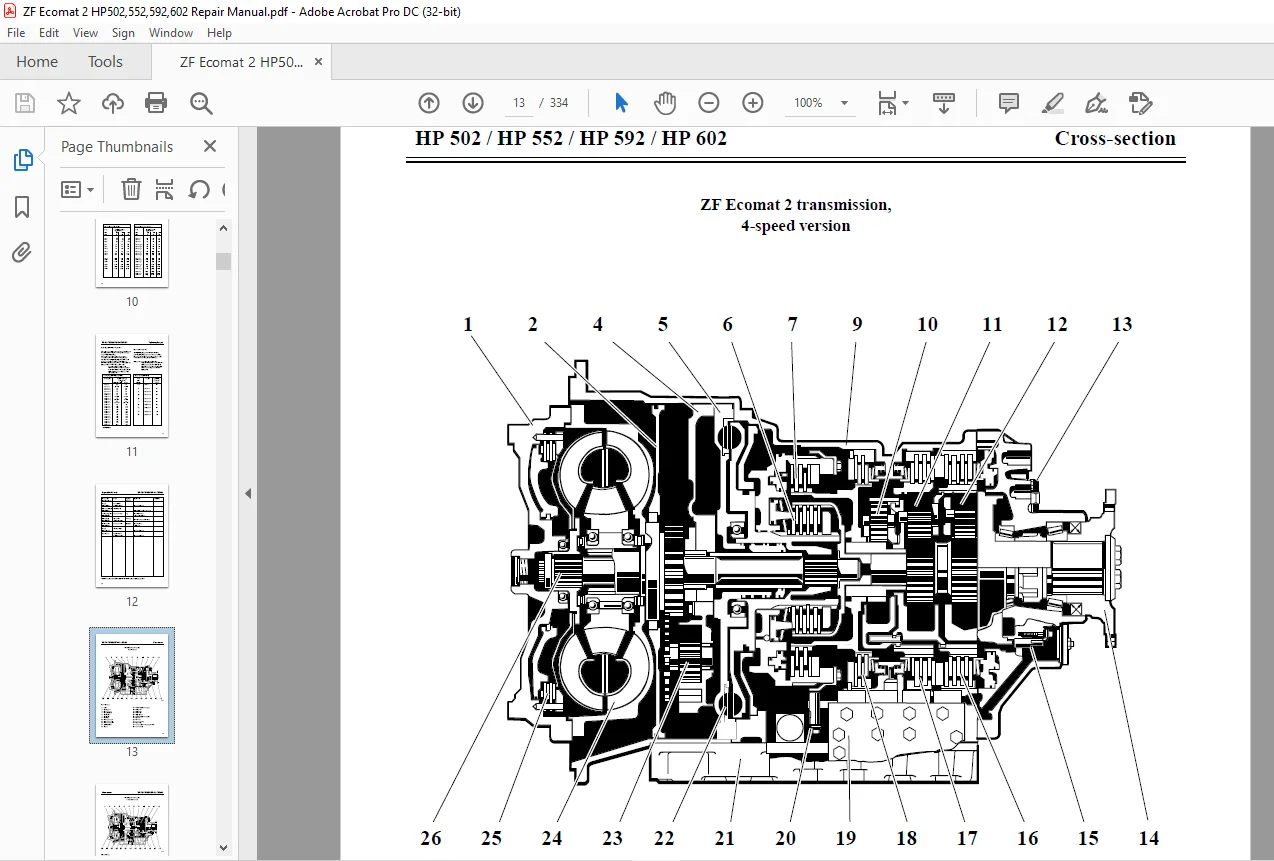
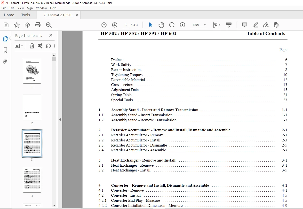
REPAIR MANUAL............................................................................  1
HP 502 / HP 552 / HP 592 / HP 602 Stage 3 4149 751 604...................................  1
Table of Contents........................................................................  3
Preface..................................................................................  6
Important Information....................................................................  7
Repair Instructions......................................................................  8
Tightening Torques....................................................................... 10
Expendable Material...................................................................... 12
Cross-section............................................................................ 13
ZF Ecomat 2 transmission, 4-speed version................................................ 13
ZF Ecomat 2 transmission, 5 & 6-speed version............................................ 14
Adjustment Data.......................................................................... 15
Spring Table............................................................................. 21
Special Tools............................................................................ 23
Assembly Stand........................................................................... 35
	1 Assembly Stand - Insert and Remove Transmission.................................... 35
		1.1 Assembly Stand - Insert Transmission......................................... 35
		1.2 Assembly Stand - Remove Transmission......................................... 37
Retarder Accumulator..................................................................... 39
	2 Retarder Accumulator - Remove and Install, Dismantle and Assemble.................. 39
		2.1 Retarder Accumulator - Remove................................................ 39
		2.2 Retarder Accumulator - Install............................................... 41
		2.3 Retarder Accumulator - Dismantle............................................. 43
		2.4 Retarder Accumulator - Assemble.............................................. 45
Heat Exchanger........................................................................... 47
	3 Heat Exchanger - Remove and Install................................................ 47
		3.1 Heat exchanger - Remove...................................................... 47
		3.2 Heat Exchanger - Install..................................................... 51
Converter................................................................................ 57
	4 Converter - Remove and Install, Dismantle and Assemble............................. 57
		4.1 Converter - Remove........................................................... 57
		4.2 Converter - Install.......................................................... 61
			4.2.1 Converter End Play - Measure........................................... 61
			4.2.2 Converter Installation Dimension - Measure............................. 65
		4.3 Converter - Dismantle........................................................ 67
			4.3.1 ZFW 380-30 Converter - Dismantle....................................... 67
			4.3.2 ZFW 360-10 Converter - Dismantle....................................... 69
			4.3.3 Stator - Dismantle..................................................... 71
			4.3.4 Stator - Assemble...................................................... 73
			4.3.5 Turbine Wheel and Circuit Cover on ZFW 380-30 Converter - Dismantle.... 75
			4.3.6 Circuit Cover and Turbine Wheel on ZFW 380-30 Converter - Assemble..... 79
			4.3.7 Turbine Wheel and Circuit Cover on ZFW 360-10 Converter - Dismantle.... 83
			4.3.8 Circuit Cover and Turbine Wheel on ZFW 360-10 Converter - Assemble..... 87
		4.4 Converter - Assemble......................................................... 91
			4.4.1 ZFW 380-30 Converter - Assemble........................................ 91
			4.4.2 Axial Bearing End Play on ZFW 380-30 Converter - Measure and Adjust.... 95
			4.4.3 ZFW 360-10 Converter -Assemble......................................... 99
			4.4.4 Axial Bearing End Play on ZFW 360-10 Converter - Measure and Adjust....101
		4.5 Converter Leak-tightness - Check.............................................105
Cover Plate..............................................................................107
	5 Cover Plate - Remove and Install...................................................107
		5.1 Cover Plate - Remove.........................................................107
		5.2 Cover Plate - Install........................................................109
Oil Pan..................................................................................111
	6 Oil Pan - Remove and Install.......................................................111
		6.1 Oil Pan - Remove.............................................................111
		6.2 Oil Pan - Install............................................................113
Inductive Pickup.........................................................................117
	7 Inductive Pickup - Remove and Install..............................................117
		7.1 Inductive Pickup - Remove....................................................117
		7.2 Inductive Pickup - Install...................................................119
Hydraulic Control Unit...................................................................123
	8 Hydraulic Control Unit - Remove and Install, Dismantle and Assemble................123
		8.1 Hydraulic Control Unit - Remove..............................................123
		8.2 Hydraulic Control Unit - Install.............................................125
		8.3 Oil Level Indicator - Remove and Install.....................................127
			8.3.1 Oil Level Indicator - Remove...........................................127
			8.3.2 Oil Level Indicator - Install..........................................128
		8.4 Hydraulic Control Unit - Dismantle...........................................131
			8.4.1 Throttle Pressure Valve - Dismantle....................................137
			8.4.2 Throttle Pressure Valve - Assemble.....................................138
			8.4.3 Valve Block F2 - Dismantle and Assemble................................139
			8.4.4 Valve Block for Brake "F" and Clutch "WK", "C" and "A" - Dismantle.....141
			8.4.5 Valve Block for Clutch "B", Brake "E" and "D" - Dismantle..............145
		8.5 Hydraulic Control Unit - Assemble............................................149
			8.5.1 Valve Block for Brake "F" and Clutch "WK", "C" and "A" - Assemble......151
			8.5.2 Valve Block for Clutch "B", Brake "E" and "D" - Assemble...............157
Retarder Valve...........................................................................167
	9 Retarder Valve- Remove and Install.................................................167
		9.1 Retarder Valve- Remove.......................................................167
		9.2 Retarder Valve-Install.......................................................169
Output Cover.............................................................................171
	10 Output Cover - Remove and Install, Dismantle and Assemble.........................171
		10.1 Output Cover/Inductive Pickup - Remove......................................171
			10.1.1 Inductive Pickup - Install............................................173
		10.2 Output Cover - Install......................................................179
			10.2.1 Sun Gear End Play - Measure...........................................179
		10.3 Output Cover - Dismantle....................................................187
		10.4 Output Cover - Assemble.....................................................193
			10.4.1Tapered Roller Bearing - Adjust........................................197
			10.4.2 F Brake Disc Play - Adjust............................................205
Mechanical Transmission Section..........................................................211
	11 Mechanical Transmission Section - Remove and Install..............................211
		11.1 Mechanical Transmission Section - Remove Version HP 502 / 552 / 592:........211
			11.1.1Planetary Carrier II - Dismantle Version HP 502 / 552 / 592:...........215
			11.1.2 Planetary Carrier II - Assemble Version HP 502 / 552 / 592:...........219
			11.1.3Planetary Carrier I - Dismantle Version HP 502 / 552 / 592: 1..........223
			11.1.4Planetary Carrier I - Assemble Version HP 502 / 552 / 592:.............225
		11.2 Mechanical Transmission Section - Remove....................................229
			11.2.1Planetary Carrier II - Dismantle.......................................235
			11.2.2 Planetary Carrier II - Assemble.......................................236
			11.2.3 Planetary Carrier I - Dismantle.......................................239
			11.2.4 Planetary Carrier I - Assemble........................................240
			11.2.5 Planetary Carrier II and I - Assemble.................................243
			11.2.6 E Piston and Disc Carrier - Remove....................................247
			11.2.7 Sun Gear - Remove from Disc Carrier...................................249
			11.2.8 Sun Gear - Install in Disc Carrier....................................249
			11.2.9 Sun Gear - Remove from Disc Carrier...................................250
			11.2.10 Sun Gear - Install in Disc Carrier...................................250
			11.2.11 Hollow Shaft / Input Shaft - Remove..................................251
		11.3 Mechanical Transmission Section - Remove....................................253
Control Unit.............................................................................267
	12 Control Unit - Remove and Install, Dismantle and Assemble.........................267
		12.1 Control Unit - Remove.......................................................267
		12.2 Control Unit - Install......................................................269
		12.3 Control Unit - Dismantle....................................................273
			12.3.1 Control Insert - Dismantle............................................274
			12.3.2 Control Insert - Assemble.............................................287
			12.3.3 Clutch Carrier - Dismantle............................................301
			12.3.4 Clutch Carrier - Assemble.............................................309
			12.3.5 Clutch Carrier Leak-tightness and Function -Check.....................324
		12.4 Control Unit - Assemble.....................................................325
D Brake..................................................................................329
	13 D Brake - Remove and Install......................................................329
		13.1 D brake - Remove............................................................329
		13.2 D Brake - Install...........................................................331
Questions? Email us: [email protected]
https://vimeo.com/874337870?share=copy
PLEASE NOTE:
- This is the SAME MANUAL used by the dealerships to diagnose your vehicle
- No waiting for couriers / posts as this is a PDF manual and you can download it within 2 minutes time once you make the payment.
- Your payment is all safe and the delivery of the manual is INSTANT – You will be taken to the DOWNLOAD PAGE.
- So have no hesitations whatsoever and write to us about any queries you may have : heydownloadss @gmail.com
S.V