Trusted Business
Verified & Licensed
Virus Free Files
100% Safe Downloads
Secure Payment
SSL Protected
Instant Delivery
Available Immediately
ZF-ECOMAT HP 500 HP 590 HP 600 Long Version Stage 3 Repair Manual 4139751621a – PDF DOWNLOAD
$28.95
ZF-ECOMAT HP 500 HP 590 HP 600 Long Version Stage 3 Repair Manual 4139751621a – PDF DOWNLOAD
Instant PDF Download
Available immediately
Save to Your Device
Download & keep forever
Antivirus Scanned
100% virus-free
Trusted Worldwide
175,000+ customers
Description
ZF-ECOMAT HP 500 HP 590 HP 600 Long Version Stage 3 Repair Manual 4139751621a – PDF DOWNLOAD
FILE DETAILS:
ZF-ECOMAT HP 500 HP 590 HP 600 Long Version Stage 3 Repair Manual 4139751621a – PDF DOWNLOAD
Language : English
Pages : 338
Downloadable : Yes
File Type : PDF
IMAGES PREVIEW OF THE MANUAL:
DESCRIPTION:
ZF-ECOMAT HP 500 HP 590 HP 600 Long Version Stage 3 Repair Manual 4139751621a – PDF DOWNLOAD
Preface:
- This manual is intended for skilled personnel who have been trained by ZF Friedrichshafen AG to carry out
maintenance and repair work on ZF products. - This manual deals with the standard ZF product in accordance with the state of development on the date of
issue. - However, due to continuing development of the product, repair work might require work practices and test or
adjustment data which are not contained in this manual. - We therefore recommend that work done on your ZF
product is carried out only by skilled mechanics who have had their practical and theoretical knowledge updated on
a regular basis at our After-Sales Service training courses.
Service points equipped by ZF Friedrichshafen AG all over the world offer you:
1. Well-trained personnel
2. Specified equipment, e.g. specialized tools
3. Genuine ZF spares, to our latest specifications
- All work performed in these service points is carried out conscientiously and with care.
- Repair work carried out at ZF service points is guaranteed in accordance with the prevailing contractual
conditions. - Damage resulting from work performed by non-ZF personnel in an improper and unprofessional manner, together
with follow-on costs caused by such work, is excluded from the contractual warranty agreement. This also applies
where genuine ZF spares have not been used.
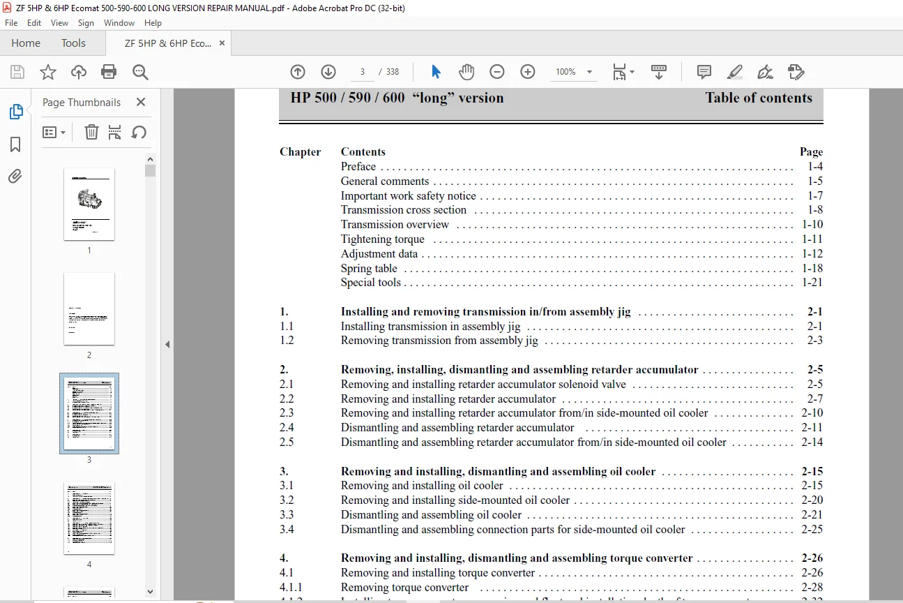
TABLE OF CONTENTS:
ZF-ECOMAT HP 500 HP 590 HP 600 Long Version Stage 3 Repair Manual 4139751621a – PDF DOWNLOAD
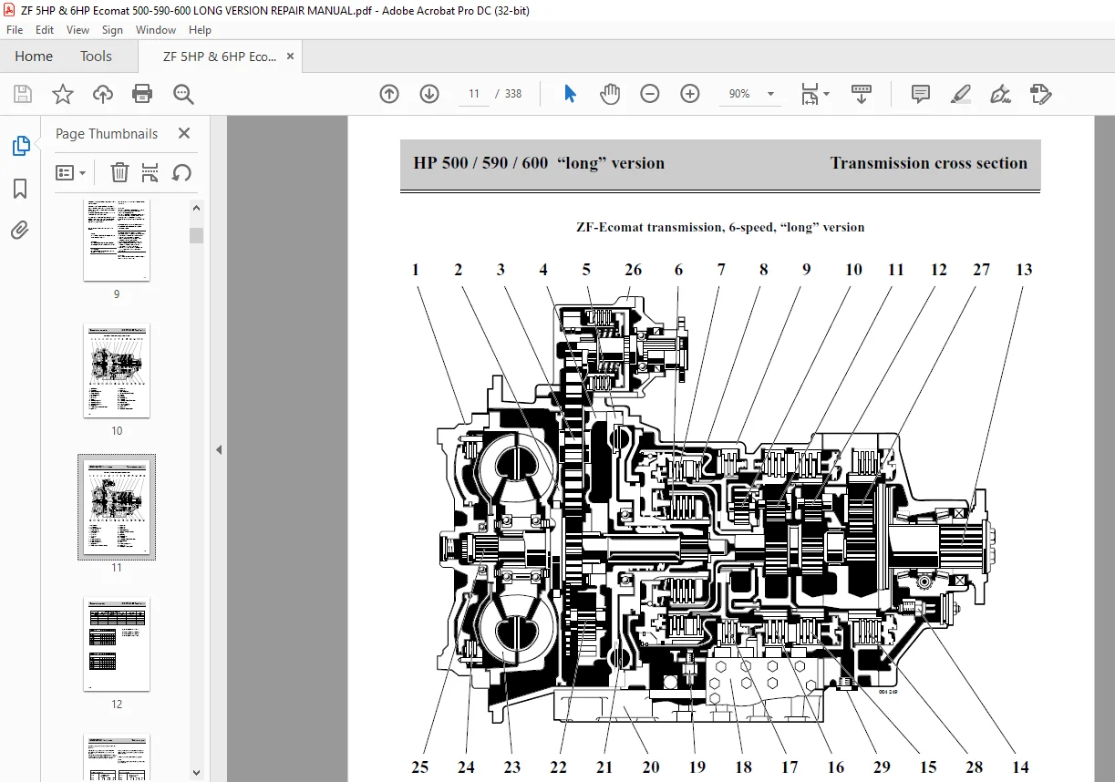
Start Service CD.............................................................................................  0
Repair manual - Ecomat - long version, Stage 3...............................................................  1
	Copyright................................................................................................  2
	Contents 1...............................................................................................  3
	Contents 2...............................................................................................  4
	Contents 3...............................................................................................  5
	Preface..................................................................................................  6
	General comments.........................................................................................  7
	Safety notice............................................................................................  9
	Transmission cross section, 5-speed...................................................................... 10
	Transmission cross section, 6-speed...................................................................... 11
	Transmission overview.................................................................................... 12
	Tightening torques....................................................................................... 13
	Adjustment data.......................................................................................... 14
	Spring table............................................................................................. 20
	Special tools............................................................................................ 23
	1 Assembly jig........................................................................................... 37
		1.1 Installing transmission in assembly jig.......................................................... 38
		1.2 Removing transmission from assembly jig.......................................................... 40
	2 Retarder accumulator................................................................................... 41
		2.1 Removing and installing solenoid valve........................................................... 41
		2.1.1 Removing solenoid valve........................................................................ 42
		2.1.2 Installing solenoid valve...................................................................... 42
		2.2 Removing and installing retarder accumulator..................................................... 43
			2.2.1 Removing retarder accumulator.............................................................. 44
			2.2.2 Installing of retarder accumulator......................................................... 45
		2.3 Removing and installing retarder accumulator..................................................... 46
		2.4 Dismantling and assembling retarder accumulator.................................................. 47
	3 Oil cooler............................................................................................. 51
		3.1 Removing and installing oil cooler............................................................... 51
		3.2 Removing and installing side-mounted oil cooler.................................................. 56
		3.3 Dismantling and assembling oil cooler............................................................ 57
	4 Torque converter....................................................................................... 62
		4.1 Removing and installing torque converter......................................................... 62
		4.1.1 Removing torque converter...................................................................... 64
		4.1.2 Installing torque converter, measuring end float and installation depth of torque converter.... 68
		4.2 Dismantling and assembling torque converter...................................................... 75
		4.2.1 Dismantling torque converter................................................................... 77
		4.2.2 Assembling toque converter, measuring end float of thrust bearing.............................. 84
		4.3  Checking torque converter for leaks............................................................. 98
	5 Cover plate............................................................................................101
		5.1 Removing cover plate.............................................................................103
		5.2 Installing cover plate...........................................................................107
	6 Oil pan................................................................................................111
		6.1 Removing oil pan.................................................................................112
		6.2 Installing oil pan...............................................................................113
	7 Inductive sensor.......................................................................................116
		7.1 Removing inductive sensor........................................................................117
		7.2 Installing inductive sensor; establishing set distance...........................................118
	8 Hydraulic transmission control unit....................................................................121
		8.1 Removing and installing hydraulic transmission control unit......................................121
			8.1.1 Removing hydraulic transmission control unit...............................................122
			8.1.2 Installing hydraulic transmission control unit.............................................123
		8.2 Dismantling and assembling hydraulic transmission control unit...................................124
			8.2.1 Dismantling hydraulic transmission control unit in sub-assemblies..........................127
			8.2.2 Assembling hydraulic transmission control unit in sub-assemblies...........................131
		8.3 Dismantling and assembling throttle valve........................................................137
			8.3.1 Dismantling throttle valve.................................................................138
		8.4 Dismantling and assembling valve block B.........................................................141
			8.4.1 Dismantling valve block B..................................................................143
			8.4.2 Assembling valve block B...................................................................147
		8.5 Dismantling and assembling valve block A.........................................................153
			8.5.1 Dismantling valve block A..................................................................155
			8.5.2 Assembling valve block A...................................................................159
	9 Retarder valve.........................................................................................165
		9.1 Removing retarder valve..........................................................................166
		9.2 Installing retarder valve........................................................................168
	10 Output................................................................................................172
		10.1 Removing and installing “output speed” inductive sensor; establishing set distance..............174
		10.2 Removing and installing speedo connection piece and screw plugs.................................178
		10.3 Removing and installing output flange...........................................................179
		10.4 Installing and removing output end cover; Measuring end float of sun gear.......................181
			10.4.1 Removing output end cover.................................................................181
			10.4.3 Adjusting disc play of brake G............................................................185
			10.4.4 Installing output end cover...............................................................187
		10.5 Dismantling and assembling output end cover.....................................................189
			10.5.1 Dismantling output end cover..............................................................191
			10.5.2 Assembling output end cover...............................................................196
	11 Intermediate housing..................................................................................205
		11.1 Removing intermediate housing...................................................................207
		11.2 Adjusting end float of sun gear.................................................................211
		11.3 Adjusting disc play of brake F..................................................................212
		11.4 Installing intermediate housing.................................................................213
	12 Mechanical transmission part..........................................................................217
		12.1 Removing, dismantling and assembling planet carriers II and I, brakes F and E...................219
			12.1.1 Removing planet carriers II and I, brakes F and E.........................................221
			12.1.2 Removing planet carriers II and I; version HP 600.........................................225
			12.1.3 Diversion HP 600smantling planet carrier II: version HP 500 / HP 590......................227
			12.1.4 Dismantling planet carrier II: version HP 600.............................................230
			12.1.5 Dismantling planet carrier I. version HP 500 / HP 590.....................................231
			12.1.6 Dismantling planet carrier I; version HP 600..............................................233
			12.1.7 Assembling planet carrier I...............................................................234
			12.1.8 Assembling planet carrier II. version HP 500 / HP 590.....................................237
			12.1.9 Assembling planet carriers II and I; version HP 600.......................................241
		12.2 Removing piston E and disc carrier..............................................................243
		12.3 Removing and installing quill shaft and drive shaft.............................................247
			12.3.1 Removing quill shaft and drive shaft......................................................248
			12.3.2 Installing quill shaft and drive shaft....................................................250
		12.4 Installing piston E and disc carrier............................................................252
		12.5 Installing planet carriers I and II, brakes E and F.............................................256
		12.6 Installing planet carriers I and II; version HP 600.............................................264
		12.7 Measuring and adjusting inductive sensor ring...................................................266
	13 Control unit..........................................................................................267
		13.1 Removing control unit...........................................................................269
			13.1.1 Dismantling control unit..................................................................271
			13.1.2 Assembling control unit...................................................................272
			13.1.3 Installing control unit...................................................................275
		13.2 Removing and installing valves of control element...............................................278
			13.2.1 Removing valves from control element......................................................280
			13.2.2 Installing valve in control element.......................................................283
		13.3 Dismantling and assembling control element......................................................287
			13.3.1 Dismantling control element...............................................................289
			13.3.2 Assembling control element................................................................297
		13.4 Dismantling and assembling clutch carrier.......................................................304
			13.4.2 Assembling clutch carrier.................................................................316
			13.4.3 Checking clutch carrier for leaks and checking function...................................331
	14 Brake D...............................................................................................332
		14.1 Removing brake D................................................................................333
		14.2 Installing brake D..............................................................................335
Customer Support: [email protected]
PLEASE NOTE:
- This is the same manual used by the dealers to diagnose and troubleshoot your vehicle
- You will be directed to the download page as soon as the purchase is completed. The whole payment and downloading process will take anywhere between 2-5 minutes
- Need any other service / repair / parts manual, please feel free to contact [email protected] . We still have 50,000 manuals unlisted
S.V