Trusted Business
Verified & Licensed
Virus Free Files
100% Safe Downloads
Secure Payment
SSL Protected
Instant Delivery
Available Immediately
ZF ERGOPOWER 4 WG-115 Repair Manual – PDF DOWNLOAD
$27.95
ZF ERGOPOWER 4 WG-115 Repair Manual – PDF DOWNLOAD
Instant PDF Download
Available immediately
Save to Your Device
Download & keep forever
Antivirus Scanned
100% virus-free
Trusted Worldwide
175,000+ customers
Description
ZF ERGOPOWER 4 WG-115 Repair Manual – PDF DOWNLOAD
FILE DETAILS:
ZF ERGOPOWER 4 WG-115 Repair Manual – PDF DOWNLOAD
Language : English
Pages : 163
Downloadable : Yes
File Type : PDF
IMAGES PREVIEW OF THE MANUAL:
DESCRIPTION:
ZF ERGOPOWER 4 WG-115 Repair Manual – PDF DOWNLOAD
PREFACE:
This documentation has been developed for specialized staff trained by ZF Passau for
repair and maintenance work to be made on ZF units.
- This documentation describes a ZF series product with a design level valid at the date of edition.
- Due to the continuous technical upgrading of the product, however, the repair of the unit at your
disposal may require both deviating work steps and differing setting and testing data. - We would therefore recommend you to entrust masters and servicemen with the work on your ZF product
whose practical and theoretical training is constantly updated in our training school. - The Service Stations established by ZF Friedrichshafen all over the world offer you:
1. Permanently trained staff
2. Specified equipment, e.g. special tools
2. Specified equipment, e.g. special tools
3. State-of-the-art genuine ZF spare parts
- All work is done there with utmost care and reliability.
In addition, repair work carried out by ZF Service Stations is covered by the ZF warranty within
the terms of the currently applicable contractual conditions. - Any damage resulting from work which is done in an improper and unprofessional manner by third
parties and any consequential costs incurred shall be excluded from this contractual liability.
This shall also be applicable if other than genuine ZF spare parts are used.
GENERAL:
The Service Manual covers all work required for disassembly and the relating reassembly.
- When repairing the unit, ensure utmost cleanliness and that the work is done in a professional
manner. Dismantle the unit only if any damaged parts must be replaced. After removing screws or
nuts, loosen lids and housing parts, which were installed with seals, by slight hammer blows with a
plastic hammer. Use suitable pulling devices for removing parts being tightly installed on the
shafts, such as bearings, bearing rings and similar. - Carry out disassembly and reassembly work on a clean working place. Use special tools which have
been developed for this purpose. Prior to reinstallation of the parts, clean contact faces of
housings and lids from residues of seals. Remove any burrs or similar irregularities with an oil
stone. Clean housings and end covers, in particular corners and angles, with a suitable detergent.
Damaged or heavily worn parts must be replaced, with an expert assessing whether parts subject to
normal wear during operation, such as bearings, thrust washers etc. will be reinstalled.
Parts such as seal rings, locking plates, split pins etc. must generally be replaced. Radial seal
rings with worn or broken sealing lip must also be replaced. In particular, ensure that no chips or
other foreign bodies remain in the housing. Check the lube oil holes and grooves regarding
unhindered passage.
Oil according to the relating List of Lubricants shall be applied to all bearings prior to their
installation.
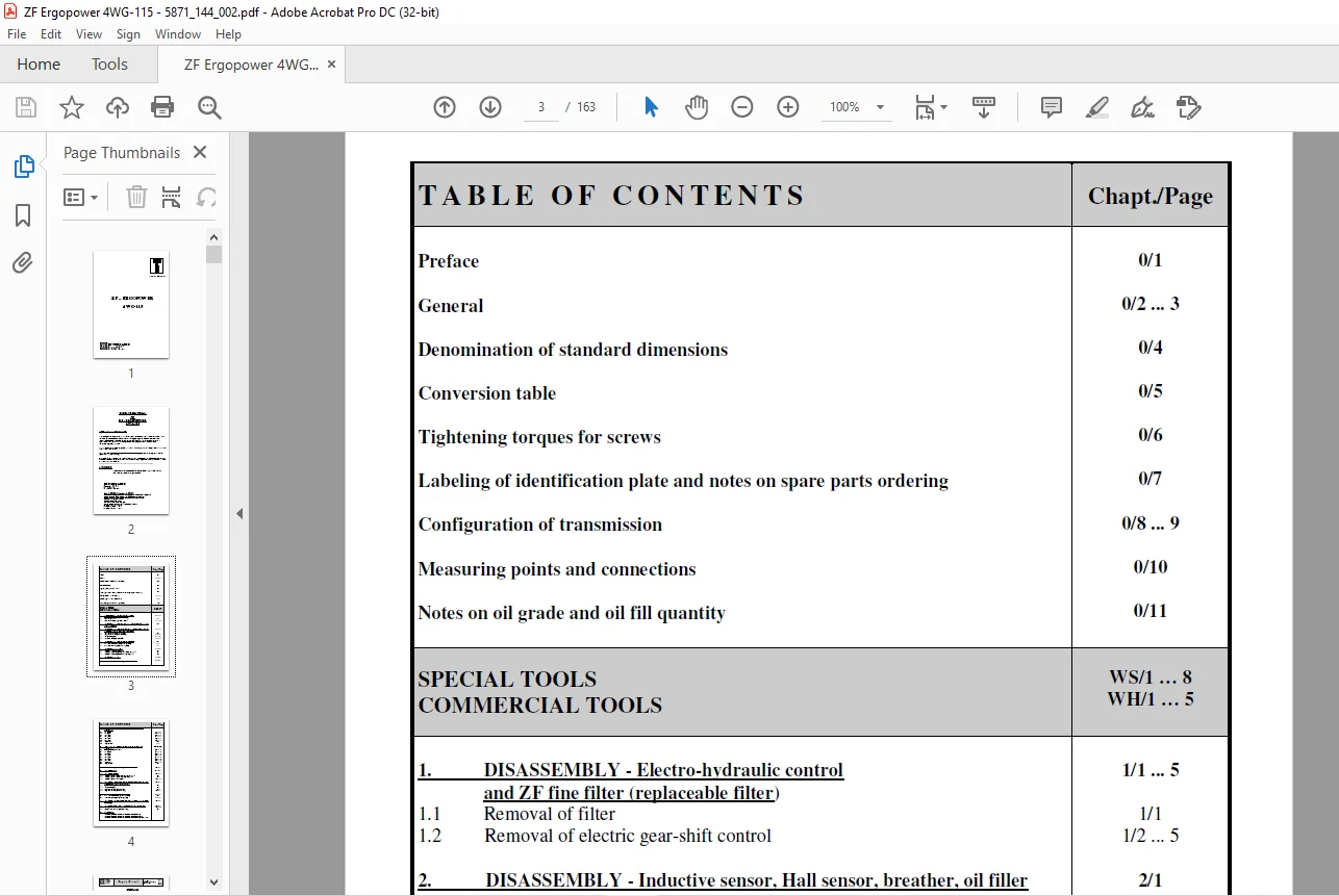
TABLE OF CONTENTS:
ZF ERGOPOWER 4 WG-115 Repair Manual – PDF DOWNLOAD
ZF - ERGOPOWER  4 WG-115...........................................................................................  1
	Note...........................................................................................................  2
	Table of Contents..............................................................................................  3
	Preface........................................................................................................  5
	General........................................................................................................  6
	Denomination of standard dimensions............................................................................  8
	Conversion table...............................................................................................  9
	Tightening torques for screws.................................................................................. 10
	Labeling of identification plate and notes on spare parts ordering............................................. 11
	Configuration of transmission.................................................................................. 12
	Measuring points and connections............................................................................... 14
	Notes on oil grade and oil fill quantity....................................................................... 15
	Special Tools.................................................................................................. 16
	Commercial Tools............................................................................................... 24
	1. Disassembly -Electro-hydraulic control and ZF fine filter (replaceable filter).............................. 29
		1.1 Removal of filter ..................................................................................... 29
		1.2 Removal of electric gear-shift control................................................................. 30
	2. Disassembly - Inductive sensor, Hall sensor, breather, oil filler and oil drain plug........................ 34
	3. Disassembly -Engine connection, oil pressure pump, converter back-pressure valve and temperature sensor..... 35
		3.1 Engine connection (direct mount).......................................................................  0
		3.2 Engine connection (remote mount).......................................................................  0
		3.3 Oil pressure pump......................................................................................  0
		3.4 Converter back-pressure valve..........................................................................  0
	4. Disassembly - Emergency steering pump....................................................................... 40
		4.1 Version without emergency steering pump................................................................  0
		4.2 Version with emergency steering pump...................................................................  0
	5. Disassembly - Outputs....................................................................................... 41
		5.1 Output flange on converter side........................................................................ 41
		5.2 Output flange on output side without parking brake..................................................... 41
		5.3 Output flange on output side with parking brake........................................................ 42
	6. Disassembly - PTO........................................................................................... 43
	7. Removal of input shaft, output shaft and clutches........................................................... 45
	8. Disassembly - Clutches KV/KR/K1/K2/K3/K4, input and output shaft............................................ 48
		8.1 KV clutch.............................................................................................. 48
		8.2 KR clutch.............................................................................................. 52
		8.3 K1 clutch.............................................................................................. 56
		8.4 K2 clutch.............................................................................................. 60
		8.5 K3 clutch.............................................................................................. 64
		8.6 K4 clutch.............................................................................................. 68
		8.7 Input shaft............................................................................................ 72
		8.8 Ouput shaft............................................................................................ 73
	9. Reassembly - Clutches KV/KR/K1/K2/K3/K4, input and output shaft............................................. 74
		9.0 General notes on the clutch............................................................................ 74
		9.1 KV clutch.............................................................................................. 76
		9.2 KR clutch.............................................................................................. 81
		9.3 K1 clutch.............................................................................................. 86
		9.4 K2 clutch.............................................................................................. 91
		9.5 K3 clutch.............................................................................................. 96
		9.6 K4 clutch..............................................................................................101
		9.7 Input shaft............................................................................................107
		9.8 Output shaft...........................................................................................109
	10. Installation of input shaft, output shaft and clutches.....................................................110
	11. Reassembly - PTO...........................................................................................116
	12. Reassembly - Outputs.......................................................................................118
		12.1 Output flange on output side without parking brake....................................................118
		12.2 Output flange on output side with parking brake.......................................................119
		12.3 Output flange on converter side.......................................................................120
	13. Reassembly - Engine connection, oil pressure pump, converter back-pressure valve and temperature sensor....122
		13.1 Converter back-pressure valve.........................................................................122
		13.2 Oil pressure pump.....................................................................................123
		13.3 Engine connection (direct mount)......................................................................126
		13.4 Engine connection (remote mount)......................................................................126
	14. Reassembly - Emergency steering pump.......................................................................130
		14.1 Version without emergency steering pump...............................................................130
		14.2 Version with emergency steering pump..................................................................130
	15. Reassembly - Inductive sensor, Hall sensor, breather , oil filler and oil drain plug.......................132
	16. Reassembly - Electro-hydraulic control with proportional valves............................................134
		16.1 Fitting of electric control...........................................................................135
		16.2 Fitting of ZF fine filter (pressure filter)...........................................................141
	17. Parking brake..............................................................................................143
		Functional characteristics and maintenance instructions M 90...............................................143
		Functional characteristics and maintenance instructions FSG 75.............................................145
		Functional characteristics and maintenance instructions FSG 90/FSG 110.....................................155
Customer Support: [email protected]
PLEASE NOTE:
- This is the SAME MANUAL used by the dealerships to diagnose your vehicle
- No waiting for couriers / posts as this is a PDF manual and you can download it within 2 minutes time once you make the payment.
- Your payment is all safe and the delivery of the manual is INSTANT – You will be taken to the DOWNLOAD PAGE.
- So have no hesitations whatsoever and write to us about any queries you may have : heydownloadss @gmail.com
S.V