Zoll 1600 Defibrillator Service Manual – PDF DOWNLOAD
Original price was: $95.00.$16.95Current price is: $16.95.
In-depth Zoll 1600 defibrillator service manual covering checkout procedures, troubleshooting guides, functional descriptions, schematics, disassembly procedures, and calibration adjustments for the Zoll 1600 pacer and defibrillator. Includes ECG tests, pacer tests, defibrillator tests, MRM details, and replacement parts for biomedical technicians. Essential for Zoll 1600 maintenance and repair, with safety considerations and service policy. 190 pages of technical schematics and functional descriptions.
Description
Zoll 1600 Defibrillator Service Manual – PDF DOWNLOAD
Description
This comprehensive Zoll 1600 defibrillator service manual provides essential technical guidance for servicing the Zoll 1600 series, a semi-automatic defibrillator with optional pacing and medical reporting module (MRM). Aimed at biomedical engineers and technicians, it details Zoll 1600 checkout procedures for routine maintenance, including initialization, leakage, power supply, ECG tests, pacer tests and troubleshooting, defibrillator tests, and real-time clock checks. The manual covers troubleshooting guides with text and status messages, functional descriptions of system components like power supply, digital board (CPU/EPU), analog board (ECG/CRT), pace/defib stimulator board, and MRM. It includes Zoll 1600 schematics and functional descriptions for interconnect diagrams, power supply, digital/analog modules, and more, alongside component layout drawings for precise repairs.
Key sections emphasize Zoll 1600 disassembly procedures, from lower housing and printer/recorder to high voltage assemblies, patient relay, and battery components. Replacement parts list field-replaceable units, while Appendix A outlines Zoll 1600 calibration and adjustment guide for intensity, X/Y-axis, impedance, and manufacturing configuration (system/MRM serial numbers). Appendix B includes the Zoll 1600 Operator’s Guide for operational reference. Safety considerations, symbols, and service policy ensure compliance during repairs.
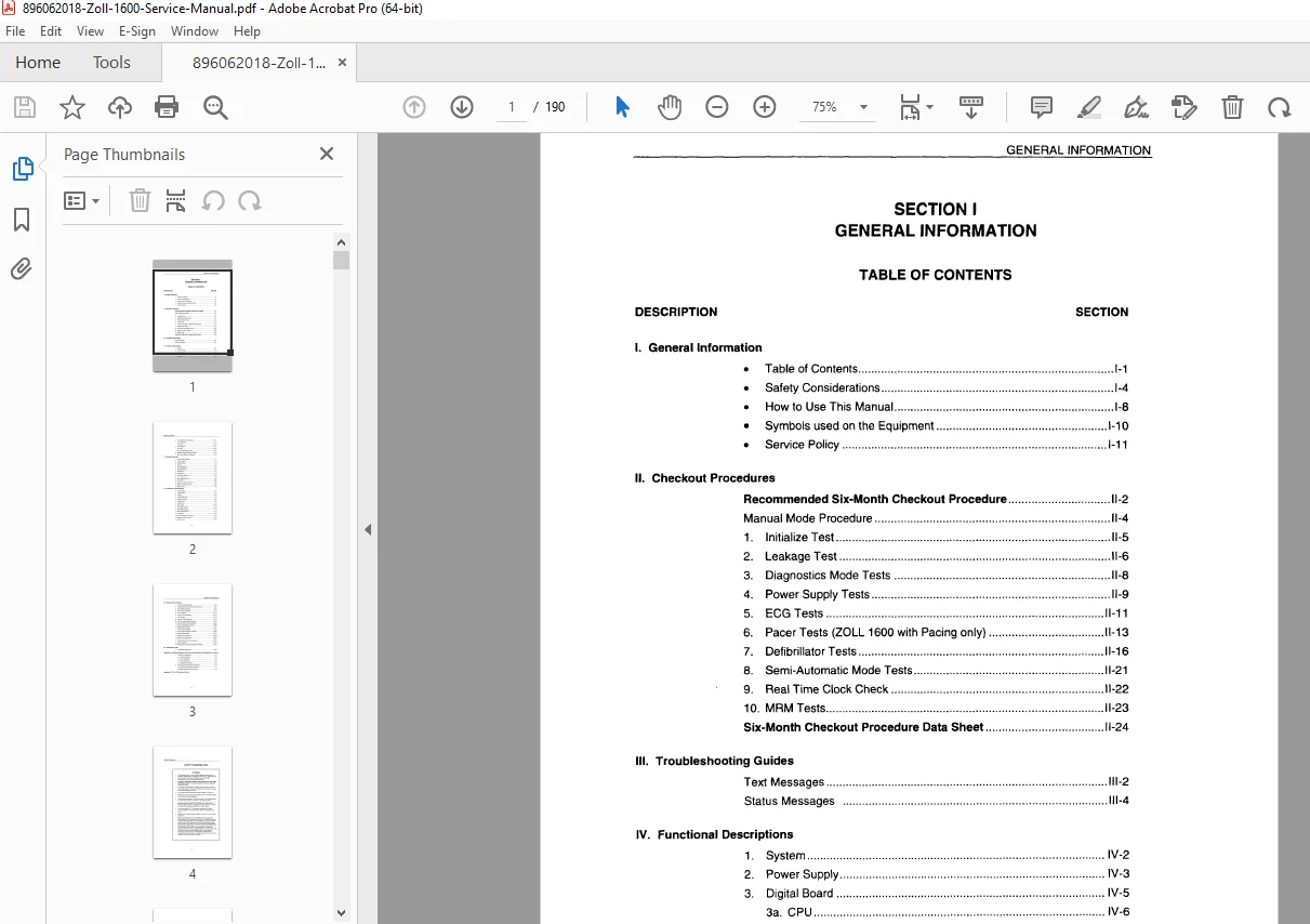
Table of Contents
| DESCRIPTION | SECTION |
|---|---|
| I. General Information | |
| • Table of Contents | I-1 |
| • Safety Considerations | I-4 |
| • How to Use This Manual | I-8 |
| • Symbols used on the Equipment | I-10 |
| • Service Policy | I-11 |
| II. Checkout Procedures | |
| Recommended Six-Month Checkout Procedure | II-2 |
| Manual Mode Procedure | II-4 |
| 1. Initialize Test | II-5 |
| 2. Leakage Test | II-6 |
| 3. Diagnostics Mode Tests | II-8 |
| 4. Power Supply Tests | II-9 |
| 5. ECG Tests | II-11 |
| 6. Pacer Tests (ZOLL 1600 with Pacing only) | II-13 |
| 7. Defibrillator Tests | II-16 |
| 8. Semi-Automatic Mode Tests | II-21 |
| 9. Real Time Clock Check | II-22 |
| 10. MRM Tests | II-23 |
| Six-Month Checkout Procedure Data Sheet | II-24 |
| III. Troubleshooting Guides | |
| Text Messages | III-2 |
| Status Messages | III-4 |
| IV. Functional Descriptions | |
| 1. System | IV-2 |
| 2. Power Supply | IV-3 |
| 3. Digital Board | IV-5 |
| 3a. CPU | IV-6 |
| 3b. EPU | IV-8 |
| 4. Pace/Defib Stimulator Board | IV-11 |
| 4a. Defibrillator | IV-11 |
| 4b. Pacer | IV-13 |
| 5. Analog Board | IV-15 |
| 5a. ECG | IV-15 |
| 5b. CRT Deflection Circuit | IV-17 |
| 6. Medical Reporting Module (MRM) | IV-18 |
| 7. Strip Chart Recorder (Optional) | IV-21 |
| V. Schematic Drawings | |
| 1. Interconnect Diagram | V-3 |
| 2. Power Supply | V-4 |
| 3. Digital Module | V-5 |
| 4. Analog | V-13 |
| 5. Pacer/Defibrillator | V-15 |
| 6. Module Interface | V-16 |
| 7. Module Port | V-17 |
| 8. Charger Port | V-17 |
| 9. Recorder Interface | V-18 |
| 10. Main MRM Section I | V-19 |
| 11. Main MRM Section II | V-24 |
| 12. Audio DSP | V-28 |
| 13. Communications Connector | V-31 |
| 14. Memory Card Connector | V-32 |
| 15. Main Control | V-33 |
| VI. Component Layout Drawings | |
| 1. Power Supply | VI-3 |
| 2. Digital Board | VI-4 |
| 3. Analog | VI-6 |
| 4. Pacer/Defibrillator | VI-7 |
| 5. Module Interface | VI-8 |
| 6. Charger Port | VI-8 |
| 7. Module Port | VI-9 |
| 8. Main Cable | VI-10 |
| 9. Recorder Interface | VI-11 |
| 10. Main MRM Section I | VI-12 |
| 11. Main MRM Section II | VI-14 |
| 12. Audio DSP | VI-16 |
| 13. Communications Connector | VI-17 |
| 14. Memory Card Connector | VI-17 |
| 15. Main Control | VI-18 |
| VII. Disassembly Procedures | |
| 1. Lower Housing Assembly | VII-5 |
| 2. Printer/Recorder or Recorder Well Filler Kit | VII-7 |
| 3. Main Cable Assembly | VII-9 |
| 4. Main Control Assembly | VII-11 |
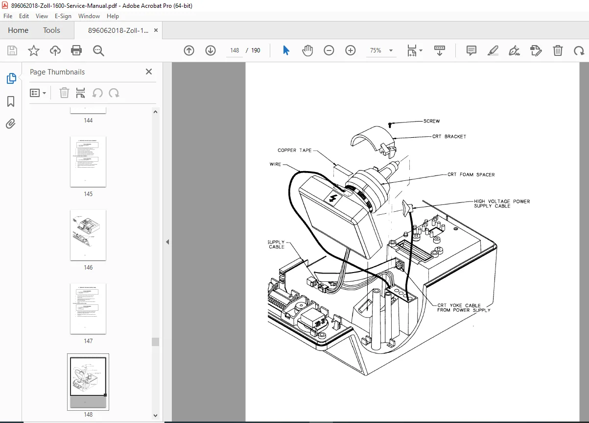
| 5. CRT Assembly | VII-13 |
| 6. Upper Control Assembly | VII-15 |
| 7. CRT Window | VII-17 |
| 8. Display Control Assembly | VII-19 |
| 9. High Voltage Multiplier Assembly | VII-21 |
| 10. Module Interface PCB Assembly | VII-23 |
| 11. Power Supply PCB Assembly | VII-25 |
| 12. Digital PCB Assembly | VII-27 |
| Analog PCB Assembly | VII-27 |
| 13. High Voltage Capacitor Assembly | VII-29 |
| 14. Defib PCB Assembly | VII-31 |
| 15. Patient Relay Assembly | VII-33 |
| 16. Battery Terminal Harness | VII-35 |
| Battery Contact Pin | VII-35 |
| 17. Patient Connector Panel Assembly | VII-37 |
| 18. Choke Assembly | VII-39 |
| 19. Medical Reporting Module (MRM) Assembly | VII-40 |
| VIII. Replacement Parts | |
| • Field Replaceable Units | VIII-2 |
| Appendix A Calibration/Adjustment Procedure & Manufacturing Configuration Procedure | |
| 1. Calibration / Adjustment | A-2 |
| 1a. Intensity Calibration | A-2 |
| 1b. X-Axis Calibration | A-2 |
| 1c. Y-Axis Calibration | A-3 |
| 1d. Impedance Calibration | A-3 |
| 2. Manufacturing Configuration Procedure | A-4 |
| 2a. System Serial Number Procedure | A-4 |
| 2b. MRM Serial Number Procedure | A-4 |
| Appendix B ZOLL 1600 Operator’s Guide |
Key Highlights and Features (Incorporating Long Tail Keywords):
- Checkout Procedures: Detailed Zoll 1600 checkout procedures for six-month maintenance, including diagnostics, power supply, ECG, and semi-automatic mode tests.
- Troubleshooting: Zoll 1600 pacer tests and troubleshooting with error messages for quick diagnostics.
- Functional Descriptions: In-depth Zoll 1600 schematics and functional descriptions for digital, analog, and pace/defib boards.
- Disassembly and Parts: Step-by-step Zoll 1600 disassembly procedures for assemblies like CRT, high voltage, and patient connectors.
- Calibration: Comprehensive Zoll 1600 calibration and adjustment guide for accurate system performance.
No index or bookmarks are present in the provided excerpt, but the detailed TOC facilitates navigation. This manual is crucial for maintaining the Zoll 1600 defibrillator service manual standards in emergency medical settings.
Short File Details
- Manual Name: Zoll 1600 Service Manual
- Models Covered: Zoll 1600 (with optional pacing and MRM)
- Year: 1995
- Manual PDF Quality: High-quality scanned document with clear text, tables, and diagrams; minor scan artifacts but fully legible
- No of Pages: 190