
1998 Nissan Sentra Electrical System Repair Manual – Section EL PDF Download
Original price was: $29.95.$17.95Current price is: $17.95.
Section EL of the 1998 Nissan Sentra service manual, covering every electrical circuit on the car – starting, charging, lighting, wipers, power windows, power door locks, theft warning, multi-remote control, ASCD and more, with full wiring diagrams, harness layouts and step-by-step trouble diagnoses.
Description
1998 Nissan Sentra Electrical System Repair Manual – Section EL
This is the complete Electrical System (EL) section of the 1998 Nissan Sentra service manual, delivered as an instant PDF download. It is the electrical volume only – not the whole workshop manual – and it is dedicated entirely to how the Sentra’s wiring, relays, lamps, motors and control units work, how to test them, and how to trace a fault from the symptom down to the connector pin.
If you are chasing a dead starter, a headlamp that will not come on, a power window that stopped halfway, a rear defogger grid that only half clears, or a theft warning system that will not arm, this 1998 Nissan Sentra electrical system repair manual is the document that gives you the actual circuit, the actual connector number and the actual voltage reading you should see.
File Details
- Manual type: Service manual – Electrical System section (EL)
- Brand: Nissan
- Model: Sentra, 1998
- Language: English
- Page count: 253 pages
- File format: PDF
- Section code: EL
Chapters Covered
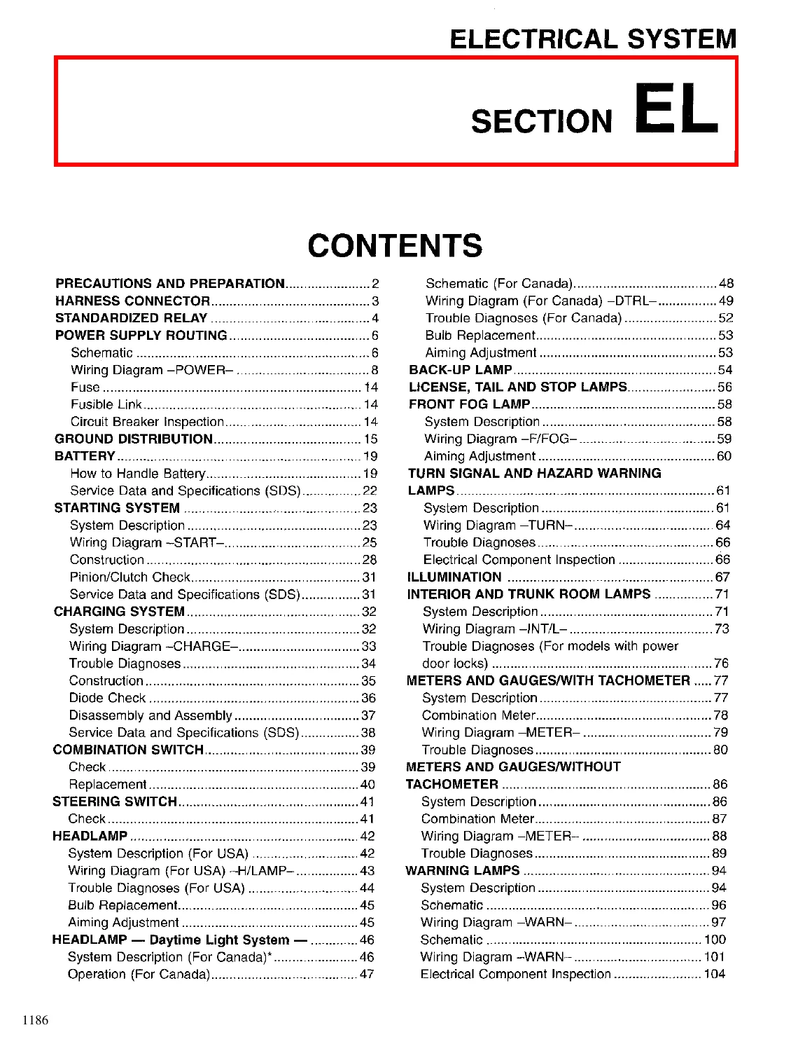
- Precautions and Preparation
- Harness Connector – locking sections, terminal retainers, water-proof types
- Standardized Relay – normal open, normal closed and mixed type relays; 1M, 1T, 2M and 1M-1B relay layouts
- Power Supply Routing – schematic, wiring diagram POWER, fuse, fusible link, circuit breaker inspection
- Ground Distribution – ground connection tables and cell codes
- Battery – handling, electrolyte level, sulphation, specific gravity check and correction chart, charging rates, service data
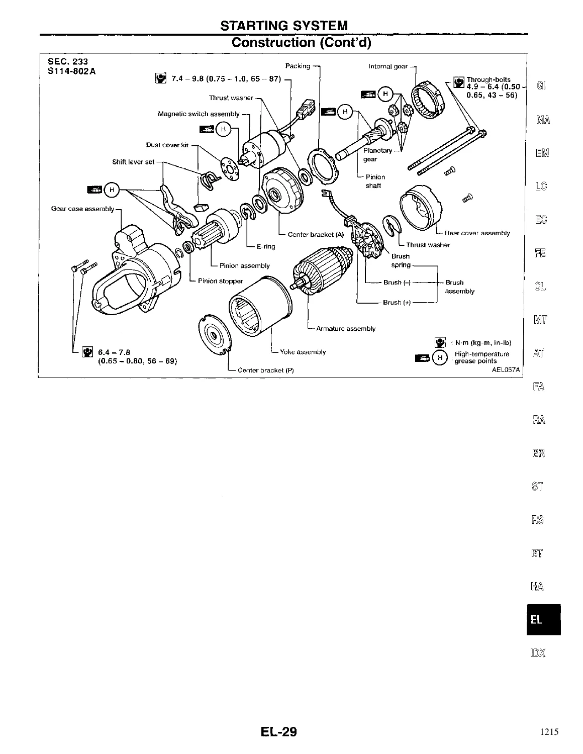
- Starting System – system description for M/T and A/T, wiring diagram START, construction, pinion/clutch check, specifications
- Charging System – system description, wiring diagram CHARGE, trouble diagnoses with IC regulator, construction, diode check, disassembly and assembly, specifications
- Combination Switch – check and replacement
- Steering Switch – check
- Headlamp (USA) – system description, wiring diagram, trouble diagnoses, bulb replacement, aiming adjustment
- Headlamp Daytime Light System (Canada) – system description, operation, schematic, wiring diagram DTRL, trouble diagnoses, bulb replacement, aiming adjustment
- Back-up Lamp
- License, Tail and Stop Lamps
- Front Fog Lamp – system description, wiring diagram, aiming adjustment
- Turn Signal and Hazard Warning Lamps – system description, wiring diagram TURN, trouble diagnoses, component inspection
- Illumination – power and ground terminal chart by component
- Interior and Trunk Room Lamps – system description, wiring diagram INT/L, trouble diagnoses
- Meters and Gauges with Tachometer – system description, combination meter, wiring diagram METER, trouble diagnoses for gauges, tachometer and speedometer
- Meters and Gauges without Tachometer – system description, combination meter, wiring diagram METER, trouble diagnoses
- Warning Lamps – system description, schematic, wiring diagram WARN, electrical component inspection
- Warning Chime – system description, wiring diagram CHIME, trouble diagnoses, electrical components inspection
- Wiper and Washer – system description, wiring diagram WIPER, trouble diagnoses, wiper installation and adjustment, washer nozzle adjustment
- Horn
- Cigarette Lighter
- Rear Window Defogger – system description, wiring diagram DEF, trouble diagnoses, filament check, filament repair
- Audio – system description, wiring diagram AUDIO, trouble diagnoses, inspection
- Electric Sunroof
- Door Mirror
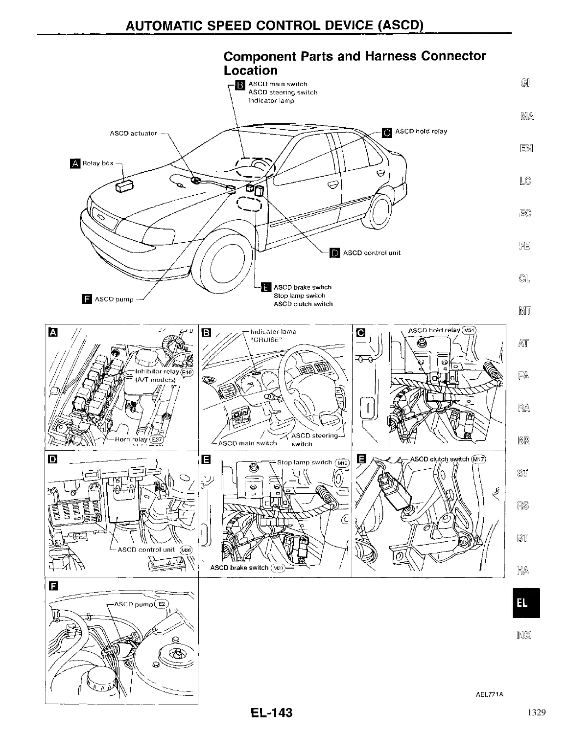
- Automatic Speed Control Device (ASCD) – component parts and harness connector location, system description, schematic, wiring diagram, fail-safe system, trouble diagnoses, ASCD wire adjustment, electrical component inspection
- Power Window – system description, wiring diagram WINDOW, trouble diagnoses
- Power Door Lock – system description, schematic, wiring diagram D/LOCK, trouble diagnoses
- Multi-Remote Control System – system description, schematic, wiring diagram MULTI, trouble diagnoses, ID code entry procedure
- Theft Warning System – component parts and harness connector location, system description, schematic, wiring diagram THEFT, trouble diagnoses
- Smart Entrance Control Unit – description and input/output operation signals
- Location of Electrical Units
- Harness Layout – main, engine room, engine control, engine No. 2 and generator, body, body No. 2, room lamp, air bag, tail, front door (2-door and 4-door) and rear door harnesses
- Bulb Specifications
- Wiring Diagram Codes (Cell Codes)
What makes this section useful is that it does not stop at a picture of the circuit. Each system is written up in three layers: a system description that explains in plain language when power is supplied, where ground comes from and what makes the relay or control unit switch; a wiring diagram that shows the same thing as a circuit with connector numbers, wire colours, splice points and ground references; and a trouble diagnosis section that takes a complaint – lamps do not operate, indicator does not flash, window will not go down – and walks it back through fuses, grounds, switches, harnesses and components in a defined order. The combination meter, warning lamp and diode checks, the fuel tank gauge unit and thermal transmitter resistance values, the vehicle speed sensor voltage test and the rear window defogger filament check all sit in the same volume, so a single electrical complaint can usually be worked end to end without leaving the document.
What You Can Diagnose With This Manual
The starting and charging chapters give you the complete crank circuit for both manual and automatic cars, including the clutch interlock relay, inhibitor relay, theft warning relay and starter cut output, plus the IC regulator test sequence, diode check procedure and the no-load and hot output figures for the generator.
The lighting chapters cover USA and Canada headlamp circuits separately, including the daytime light control unit that runs the high beams at half brightness in series – one of the few places that circuit is documented in full, with the terminal voltage table and parking brake logic spelled out.
For body electrics, the power window and power door lock sections include the express down circuit, the power window lock, the key reminder door system and the door unlock sensor logic. The multi-remote control and theft warning chapters cover the smart entrance control unit inputs and outputs, the ID code entry procedure, panic alarm operation and hazard reminder flashing, all with diagnostic procedures that show you which terminal to probe and what voltage or continuity to expect.
Under the hood and behind the dash, the harness layout drawings show routing and connector positions for the main, engine room, engine control, body, room lamp, air bag, tail and door harnesses, so you can physically find the connector a diagram refers to instead of guessing.
Why the Correct Electrical Data Matters
Electrical faults punish guesswork. Replacing a relay that was never the problem, or chasing a ground that was fine, costs time and often creates new faults in brittle 1998-era connectors. This manual removes the guessing by giving the factory wire colours, connector numbers, ground locations and expected readings, so a circuit can be proved good or bad before a part is touched. It also documents the interaction between systems – how the theft warning system interrupts the starter, how the smart entrance control unit drives the interior lamp timer, how the ASCD hold relay keeps the cruise circuit alive after the main switch is released – which is exactly where intermittent faults usually hide.
IMAGES PREVIEW
Instant PDF Delivery
The 1998 Nissan Sentra Electrical System repair manual is delivered as an immediate PDF download after checkout. There is no shipping, no waiting and no physical book to lose. Open it on a laptop, tablet or phone in the garage, print only the diagram pages you need for the job, and keep the rest of the volume intact. Because the file is organised by system, you can jump straight to the section that matches the fault in front of you and work from the wiring diagram and trouble diagnosis chart without paging through an entire workshop manual.
Reviews
There are no reviews yet.