
2001 Cummins NTC-400 Big Cam I & III Diesel Engine DS/GS Maintenance Repair Parts Manual TM 9-2815-225-34&P
Original price was: $44.95.$27.95Current price is: $27.95.
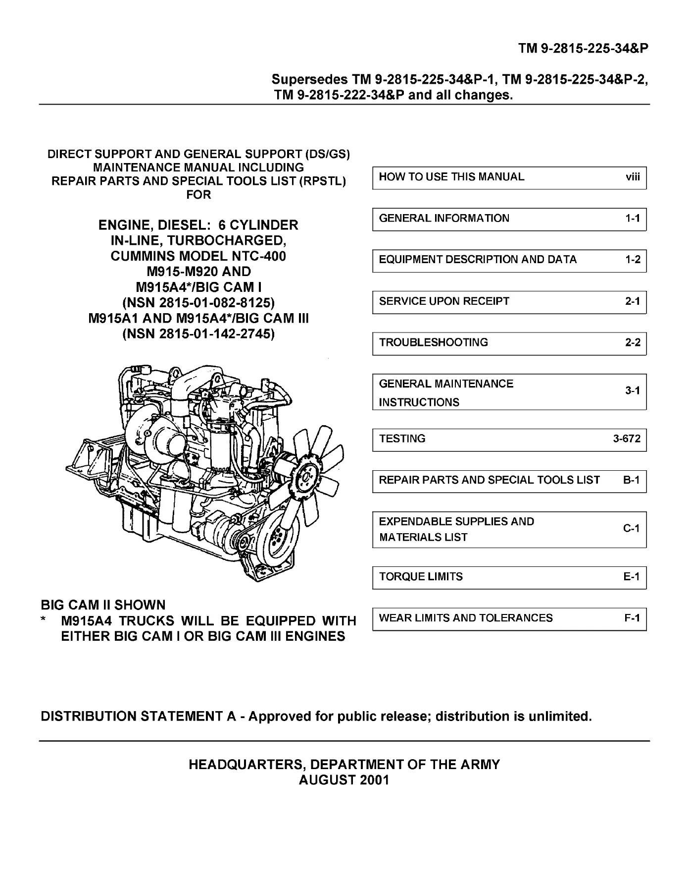
Complete 2001 Direct Support and General Support maintenance reference for the Cummins NTC-400 six-cylinder in-line turbocharged diesel engine in M915 through M920 and M915A4 Big Cam I applications, plus M915A1 and M915A4 Big Cam III applications. Covers troubleshooting, engine disassembly and assembly, component repair, injector and fuel-pump testing, torque limits, wear limits, illustrated repair parts, special tools, and storage procedures.
Description
2001 Cummins NTC-400 Big Cam I & III Diesel Engine DS/GS Maintenance Repair Parts Manual TM 9-2815-225-34&P
The 2001 Cummins NTC-400 Big Cam I & III Diesel Engine DS/GS Maintenance Repair Parts Manual TM 9-2815-225-34&P is a Direct Support and General Support maintenance reference built around the Cummins NTC-400 six-cylinder, in-line, turbocharged diesel engine. Its coverage separates the Big Cam I and Big Cam III applications where their components or procedures differ: M915 through M920 and M915A4 trucks with Big Cam I engines, and M915A1 and M915A4 trucks with Big Cam III engines. The manual combines troubleshooting, complete engine disassembly, component-level repair, reassembly, testing, storage, repair parts, special tools, torque limits, and wear limits in one extensive technical publication.
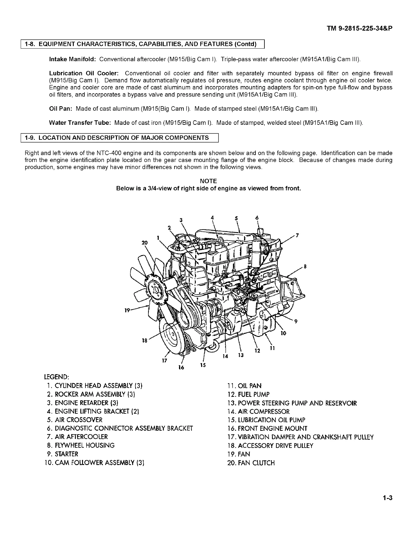
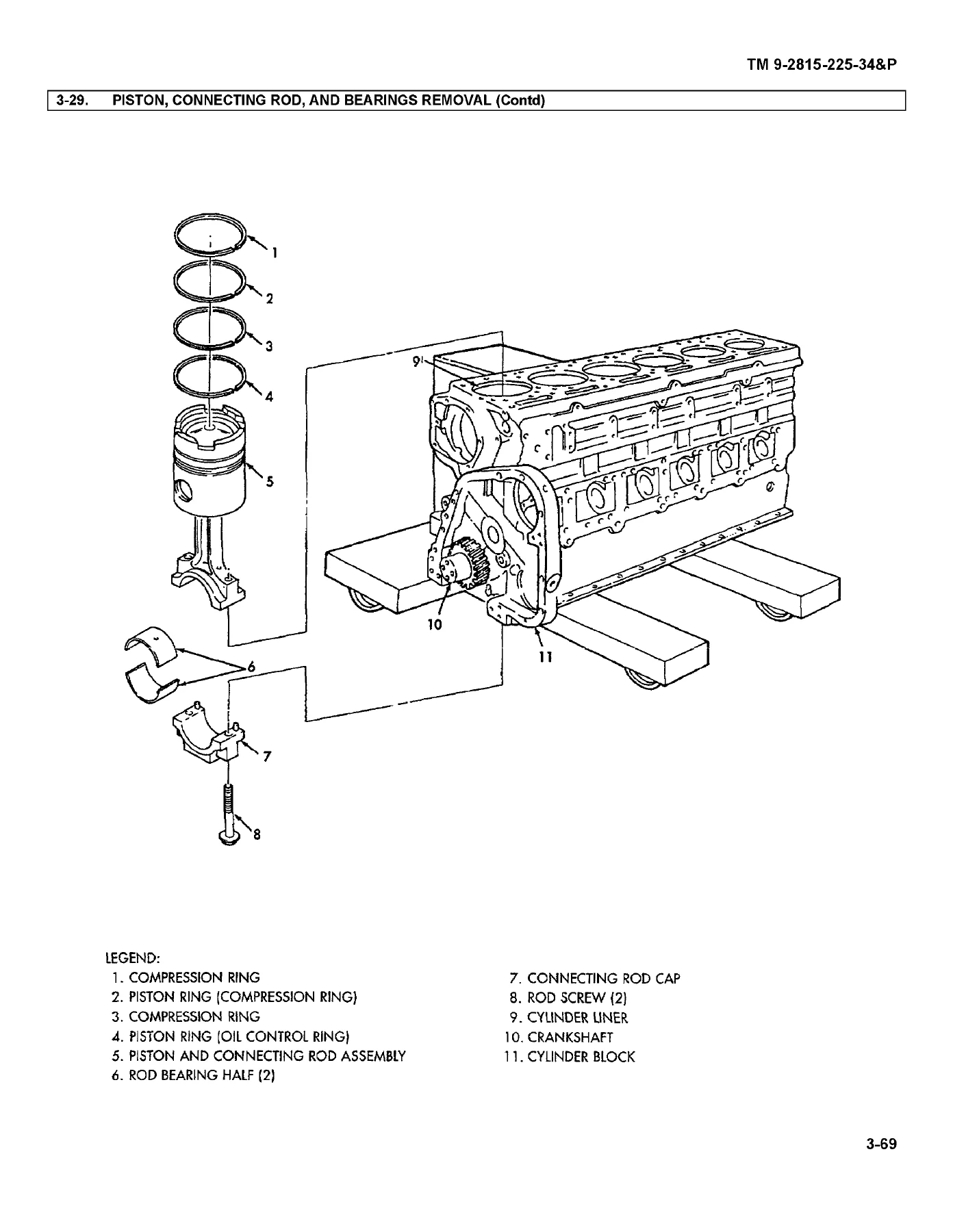
This manual is especially useful when the job goes beyond routine service. Its maintenance tasks are arranged so they can be followed in sequence for a complete engine teardown, but the publication also explains that individual procedures can be used with the troubleshooting section to repair a specific component without carrying out a full overhaul. Illustrated procedures identify parts by callout number and pair the drawings with detailed location/item, action, and remarks instructions.
File Details
- Manual type: Direct Support and General Support (DS/GS) Maintenance Manual Including Repair Parts and Special Tools List (RPSTL)
- Brand / engine: Cummins NTC-400
- Engine description: six-cylinder, in-line, turbocharged diesel
- Coverage: M915 through M920 and M915A4 / Big Cam I; M915A1 and M915A4 / Big Cam III
- Technical manual: TM 9-2815-225-34&P
- Date: 28 August 2001
- Language: English
- Page count: 934 PDF pages
- File format: PDF
Big Cam I and Big Cam III Coverage
The manual identifies the NTC-400 as a turbocharged, liquid-cooled, overhead-valve, four-cycle, in-line six-cylinder engine. It also records configuration differences instead of treating Big Cam I and Big Cam III as identical. Examples include a T-50 turbocharger for the M915/Big Cam I configuration and a T-46-B turbocharger for the M915A1/Big Cam III configuration, different exhaust-manifold designs, different aftercooler arrangements, different lubrication-oil-cooler arrangements, and cast-aluminum versus stamped-steel oil pans. Procedures throughout the maintenance section mark model-specific steps where required.
Equipment data in TM 9-2815-225-34&P provides the working reference values needed to identify and evaluate the engine. The NTC-400 is listed at 855 cu-in. (14 L) displacement with a 5.5 in. bore and 6 in. stroke. The manual gives 400 BHP maximum output, along with configuration-specific compression ratios and torque figures. Lubrication pressures and capacities, cooling-system operating temperature, governed speeds, dimensions, dry weight, fuel-flow data and other operating information are also included in the equipment-data section.
IMAGES PREVIEW
Chapters Covered
- Chapter 1 – Introduction
- General Information
- Equipment Description and Data
- Chapter 2 – Service and Troubleshooting Instructions
- Repair Parts, Special Tools, TMDE, and Support Equipment
- Service Upon Receipt of Equipment
- Troubleshooting and Mechanical Troubleshooting
- Chapter 3 – Maintenance
- General Maintenance Instructions: lifting, draining, cleaning, inspection, wear limits, repair, and assembly practices
- Disassembly: engine stand mounting; vibration damper and crankshaft pulley; accessory drive; fuel pump; air compressor; oil pump; aftercooler; engine retarder; rocker assemblies; injectors; cylinder heads; flywheel or flexplate; oil pan; gear cover; camshaft; pistons; liners; crankshaft and main bearings
- Repair: engine block; cylinder head and valves; crankshaft; piston and connecting rod assemblies; camshaft and followers; rocker levers; oil cooler and oil pump; aftercooler; exhaust manifold; turbocharger; accessory drive; engine retarder; air compressor; injectors; fuel-pump components; water pump
- Assembly: cylinder liners; crankshaft and main bearings; pistons and rods; camshaft and followers; cylinder heads and pushrods; injection timing; lubrication components; accessory drive; air compressor; fuel pump; vibration damper; flywheel or flexplate; oil pan; injectors; valve crossheads; rocker housings; injector and valve adjustment; engine retarder; aftercooler
- Testing: starting the repaired engine, engine dynamometer testing, and on-engine fuel-pump adjustment
- Storage: temporary storage, long-term storage, and preparing an engine from storage to service
- Appendix A – Reference
- Publication indexes, forms, and related publications
- Appendix B – Repair Parts and Special Tools List
- RPSTL introduction and column explanations
- Engine repair-parts groups
- Fuel-system repair-parts groups
- Cooling-system repair-parts groups
- Repair kits and bulk material
- Direct Support and General Support special tools
- National Stock Number and part-number cross-reference indexes
- Appendix C – Expendable/Durable Supplies and Materials List
- Appendix D – Illustrated List of Manufactured Items
- Manufactured item part-number index
- Illustrated manufacturing instructions
- Appendix E – Torque Limits
- Standard torque specifications
- Engine assembly tightening specifications
- Appendix F – Wear Limits and Tolerances
- Repair standards
- Glossary and Index
The scope is broad enough to support a complete NTC-400 engine rebuild workflow while still providing direct entry points for a single fault or component repair. Rather than stopping at removal and replacement, the manual follows major assemblies through cleaning, inspection, measurement, repair, testing and installation. The appendices then supply the tightening data, wear standards, parts identification and tool references needed to complete those tasks against defined limits.
Troubleshooting Linked to Corrective Procedures
The troubleshooting section is organized by malfunction, test or inspection, and corrective action, with paragraph references that lead directly into the maintenance procedures. The symptom index covers an engine that will not crank, cranks but will not start, stops or fails to stop, overheats, produces excessive exhaust smoke, develops low oil pressure or knocking, consumes excessive fuel or oil, vibrates, will not idle, leaks fuel, loses power, misses or runs erratically, produces excessive gear noise, loses oil, forms crankcase sludge, suffers oil dilution or low compression, and overspeeds.
That structure makes the Cummins NTC-400 Big Cam I and III maintenance manual useful for diagnosis as well as overhaul. For example, troubleshooting can direct a technician from a symptom to checks involving valves, injectors, fuel-pump components, turbocharger, cylinder liners, pistons, bearings, timing, lubrication or cooling components, then point to the appropriate repair or adjustment procedure.
Engine Repair, Inspection and Reassembly Depth
Major repair procedures are developed in detail. Engine-block work includes inspection of cylinder sleeves, bearing caps, camshaft bushings, counterbores and related surfaces, with dimensional checks and repair limits. Cylinder-head and valve procedures cover disassembly, cleaning, inspection, valve guides, valve-seat inserts, injector sleeves, assembly and testing. The manual also provides dedicated procedures for the crankshaft, pistons and connecting rods, camshaft and followers, rocker levers, lubrication components, turbocharger, air compressor, engine retarder and water pump.
The fuel system receives extensive treatment. In addition to fuel-pump and injector removal and repair, the manual includes three injector-test procedures and a fuel-pump testing and calibration section. Fuel-pump calibration content covers mounting to the test stand, run-in, vacuum and seal checks, governor cut-off rpm, throttle leakage and travel, idle-speed checks, main-pressure adjustment, calibration check points and Air Fuel Control settings. Assembly procedures include injection timing plus injector and valve adjustment after major components are installed.
Initial-setup blocks are a recurring part of the maintenance tasks and identify applicable models, special tools, test equipment, materials and parts, personnel, references, equipment conditions, environmental conditions and safety instructions. That layout is valuable during larger jobs because it shows what must be prepared before a procedure begins. The illustrated pages then use numbered callouts and exploded views to show component relationships and support the step-by-step instructions.
Repair Parts, Special Tools, Torque and Wear Data
The included Repair Parts and Special Tools List is more than a general parts overview. It organizes engine, fuel-system and cooling-system parts into illustrated functional groups and includes repair kits, bulk material, special tools, and National Stock Number and part-number indexes. The RPSTL explains the Source, Maintenance, and Recoverability coding used with listed items and cross-references parts to their illustration figures and item numbers.
Appendix E provides standard torque specifications and engine-assembly tightening specifications, while Appendix F contains wear limits, tolerances and repair standards. These sections complement the main procedures, where individual tasks also specify tightening values, clearances, measurements, limits and model-specific differences. The result is a maintenance reference that supports inspection decisions as well as the physical sequence of disassembly and reassembly.
Get the NTC-400 Repair Reference Ready for the Job
The 2001 Cummins NTC-400 Big Cam I & III Diesel Engine DS/GS Maintenance Repair Parts Manual TM 9-2815-225-34&P supports fault diagnosis, complete teardown, component repair, dimensional inspection, fuel-system testing, engine assembly, adjustment, final testing and parts identification for the covered Big Cam I and Big Cam III applications. Having the specified procedures, torque information and wear limits at hand helps keep repair decisions tied to the measurements and sequences provided for the NTC-400 instead of relying on memory or approximations.
Purchase includes instant PDF delivery after payment. There is no physical book and no shipping delay: open the manual on a computer, tablet or phone, keep it available at the workbench, and print the pages you need for the repair.
Reviews
There are no reviews yet.