Trusted Business
Verified & Licensed
Virus Free Files
100% Safe Downloads
Secure Payment
SSL Protected
Instant Delivery
Available Immediately
2001 INFINITI Q45 FY33 Series Service Manual PDF DOWNLOAD
$24.95
2001 INFINITI Q45 FY33 Series Service Manual PDF DOWNLOAD
Instant PDF Download
Available immediately
Save to Your Device
Download & keep forever
Antivirus Scanned
100% virus-free
Trusted Worldwide
175,000+ customers
Description
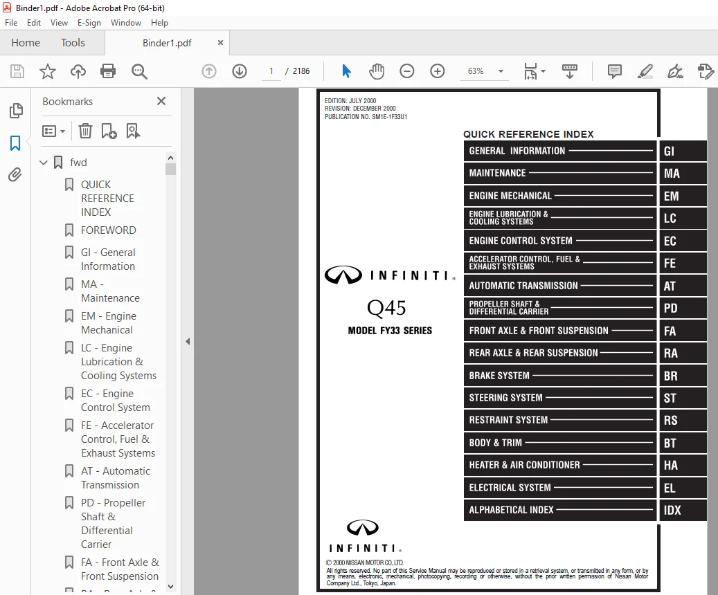
2001 INFINITI Q45 FY33 Series Service Manual PDF DOWNLOAD
FILE DETAILS:
2001 INFINITI Q45 FY33 Series Service Manual PDF DOWNLOAD
Language : English
Pages : 2186
Downloadable : Yes
File Type : PDF
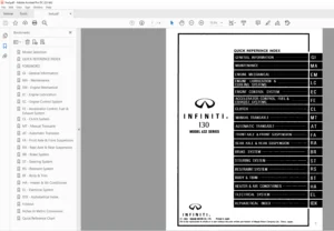
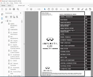
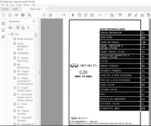
IMAGES PREVIEW OF THE MANUAL:
TABLE OF CONTENTS:
2001 INFINITI Q45 FY33 Series Service Manual PDF DOWNLOAD
fwd...............................................................................................................................................................   1
	QUICK REFERENCE INDEX.........................................................................................................................................   1
	FOREWORD......................................................................................................................................................   2
	GI - General Information......................................................................................................................................   0
	MA - Maintenance..............................................................................................................................................   0
	EM - Engine Mechanical........................................................................................................................................   0
	LC - Engine Lubrication & Cooling Systems.....................................................................................................................   0
	EC - Engine Control System....................................................................................................................................   0
	FE - Accelerator Control, Fuel & Exhaust Systems..............................................................................................................   0
	AT - Automatic Transmission...................................................................................................................................   0
	PD - Propeller Shaft & Differential Carrier...................................................................................................................   0
	FA - Front Axle & Front Suspension............................................................................................................................   0
	RA - Rear Axle & Rear Suspension..............................................................................................................................   0
	BR - Brake system.............................................................................................................................................   0
	ST - Steerring System.........................................................................................................................................   0
	RS - Restraint System.........................................................................................................................................   0
	BT - Body & Trim..............................................................................................................................................   0
	HA - Heater & Air Conditioner.................................................................................................................................   0
	EL - Electrical System........................................................................................................................................   0
	IDX - Alphabetical Index......................................................................................................................................   1
	SUPER MULTIPLE JUNCTION (SMJ).................................................................................................................................   0
	FUSE BLOCK - JUNCTION BOX (J/B)...............................................................................................................................   4
	FUSE AND FUSIBLE LINK BOX.....................................................................................................................................   5
	ELECTRICAL UNITS..............................................................................................................................................   6
	JOINT CONNECTOR (J/C).........................................................................................................................................   7
	QUICK REFERENCE CHART.........................................................................................................................................   8
	Comment Sheet.................................................................................................................................................   3
	Inch to Metric Conversion Table...............................................................................................................................   4
	GST Mode 6 - Test Value & Test Limit Chart....................................................................................................................   5
at................................................................................................................................................................   6
	QUICK REFERENCE INDEX.........................................................................................................................................   0
	Table of Contents.............................................................................................................................................   6
	DIAGNOSTIC TROUBLE CODE INDEX.................................................................................................................................   8
		Alphabetical & P No. Index for DTC........................................................................................................................   8
	PRECAUTIONS AND PREPARATION...................................................................................................................................   9
		Precautions for Supplemental Restraint System (SRS) "AIR BAG" and "SEAT BELT PRE-TENSIONER"...............................................................   9
		Precautions for On Board Diagnostic (OBD) System of A/T and Engine........................................................................................   9
		Precautions...............................................................................................................................................  10
		Service Notice or Precautions.............................................................................................................................  11
		Special Service Tools.....................................................................................................................................  13
	OVERALL SYSTEM................................................................................................................................................  15
		A/T Electrical Parts Location.............................................................................................................................  15
		Circuit Diagram...........................................................................................................................................  16
		Wiring Diagram............................................................................................................................................  17
		Cross-sectional View......................................................................................................................................  23
		Hydraulic Control Circuits................................................................................................................................  24
		Shift Mechanism...........................................................................................................................................  25
		Control System............................................................................................................................................  34
		Control Mechanism.........................................................................................................................................  36
		Control Valve.............................................................................................................................................  41
	ON BOARD DIAGNOSTIC SYSTEM DESCRIPTION........................................................................................................................  43
		Introduction..............................................................................................................................................  43
		OBD-II Function for A/T System............................................................................................................................  43
		One or Two Trip Detection Logic of OBD-II.................................................................................................................  43
		OBD-II Diagnostic Trouble Code (DTC)......................................................................................................................  43
		Malfunction Indicator Lamp (MIL)..........................................................................................................................  47
		CONSULT-II................................................................................................................................................  47
		Diagnostic Procedure without CONSULT-II...................................................................................................................  54
	TROUBLE DIAGNOSIS - Introduction..............................................................................................................................  59
		Introduction..............................................................................................................................................  59
		Diagnostic Worksheet......................................................................................................................................  60
		Work Flow.................................................................................................................................................  63
	TROUBLE DIAGNOSIS - Basic Inspection..........................................................................................................................  64
		A/T Fluid Check...........................................................................................................................................  64
		Stall Test................................................................................................................................................  64
		Line Pressure Test........................................................................................................................................  67
		Road Test.................................................................................................................................................  69
	TROUBLE DIAGNOSIS - General Description.......................................................................................................................  79
		Symptom Chart.............................................................................................................................................  79
		TCM Terminals and Reference Value.........................................................................................................................  82
	TROUBLE DIAGNOSIS FOR DTC P0705...............................................................................................................................  86
		Park/Neutral Position (PNP) Switch........................................................................................................................  86
	TROUBLE DIAGNOSIS FOR DTC P0710...............................................................................................................................  90
		A/T Fluid Temperature Sensor..............................................................................................................................  90
	TROUBLE DIAGNOSIS FOR DTC P0720...............................................................................................................................  94
		Vehicle Speed Sensor・A/T (Revolution sensor)..............................................................................................................  94
	TROUBLE DIAGNOSIS FOR DTC P0725...............................................................................................................................  97
		Engine Speed Signal.......................................................................................................................................  97
	TROUBLE DIAGNOSIS FOR DTC P0731............................................................................................................................... 100
		A/T 1st Gear Function..................................................................................................................................... 100
	TROUBLE DIAGNOSIS FOR DTC P0732............................................................................................................................... 105
		A/T 2nd Gear Function..................................................................................................................................... 105
	TROUBLE DIAGNOSIS FOR DTC P0733............................................................................................................................... 109
		A/T 3rd Gear Function..................................................................................................................................... 109
	TROUBLE DIAGNOSIS FOR DTC P0734............................................................................................................................... 113
		A/T 4th Gear Function..................................................................................................................................... 113
	TROUBLE DIAGNOSIS FOR DTC P0740............................................................................................................................... 119
		Torque Converter Clutch Solenoid Valve.................................................................................................................... 119
	TROUBLE DIAGNOSIS FOR DTC P0744............................................................................................................................... 123
		A/T TCC S/V Function (Lock-up)............................................................................................................................ 123
	TROUBLE DIAGNOSIS FOR DTC P0745............................................................................................................................... 130
		Line Pressure Solenoid Valve.............................................................................................................................. 130
	TROUBLE DIAGNOSIS FOR DTC P0750............................................................................................................................... 134
		Shift Solenoid Valve A.................................................................................................................................... 134
	TROUBLE DIAGNOSIS FOR DTC P0755............................................................................................................................... 138
		Shift Solenoid Valve B.................................................................................................................................... 138
	TROUBLE DIAGNOSIS FOR DTC P1705............................................................................................................................... 142
		Throttle Position Sensor.................................................................................................................................. 142
	TROUBLE DIAGNOSIS FOR DTC P1760............................................................................................................................... 148
		Overrun Clutch Solenoid Valve............................................................................................................................. 148
	TROUBLE DIAGNOSIS FOR BATT/FLUID TEMP SEN..................................................................................................................... 152
		A/T Fluid Temperature Sensor Circuit and TCM Power Source................................................................................................. 152
	TROUBLE DIAGNOSIS FOR VHCL SPEED SEN・MTR...................................................................................................................... 156
		Vehicle Speed Sensor・MTR.................................................................................................................................. 156
	TROUBLE DIAGNOSIS FOR TURBINE REV............................................................................................................................. 159
		Turbine Revolution Sensor................................................................................................................................. 159
	TROUBLE DIAGNOSIS FOR A/T COMM LINE........................................................................................................................... 162
		A/T Communication Line.................................................................................................................................... 162
	CONTROL UNIT (RAM), CONTROL UNIT (ROM)........................................................................................................................ 165
		TCM (Transmission Control Module)......................................................................................................................... 165
	TROUBLE DIAGNOSES FOR SYMPTOMS................................................................................................................................ 167
		1. O/D OFF Indicator Lamp Does Not Come On................................................................................................................ 167
		2. Engine Cannot Be Started In "P" and "N" Position....................................................................................................... 168
		3. In "P" Position, Vehicle Moves Forward Or Backward When Pushed......................................................................................... 168
		4. In "N" Position, Vehicle Moves......................................................................................................................... 169
		5. Large Shock. "N" -> "R" Position....................................................................................................................... 170
		6. Vehicle Does Not Creep Backward In "R" Position........................................................................................................ 171
		7. Vehicle Does Not Creep Forward In "D", "2" Or "1" Position............................................................................................. 172
		8. Vehicle Cannot Be Started From D1...................................................................................................................... 173
		9. A/T Does Not Shift: D1 -> D2 Or Does Not Kickdown: D4 -> D2............................................................................................ 174
		10. A/T Does Not Shift: D2 -> D3.......................................................................................................................... 175
		11. A/T Does Not Shift: D3 -> D4.......................................................................................................................... 176
		12. A/T Does Not Perform Lock-up.......................................................................................................................... 177
		13. A/T Does Not Hold Lock-up Condition................................................................................................................... 178
		14. Lock-up Is Not Released............................................................................................................................... 178
		15. Engine Speed Does Not Return To Idle (Light Braking D4 -> D3)......................................................................................... 179
		16. Vehicle Does Not Start From D1........................................................................................................................ 180
		17. A/T Does Not Shift: D4 -> D3, When Overdrive Control Switch "ON" -> "OFF"............................................................................. 180
		18. A/T Does Not Shift: D3 -> 22, When Selector Lever "D" -> "2" Position................................................................................. 181
		19. A/T Does Not Shift: 22 -> 11, When Selector Lever "2" -> "1" Position................................................................................. 181
		20. Vehicle Does Not Decelerate By Engine Brake........................................................................................................... 182
		21. TCM Self-diagnosis Does Not Activate (Park/Neutral Position, Overdrive Control and Throttle Position Switch Circuit Checks)........................... 182
	TROUBLE DIAGNOSES - A/T Shift Lock System..................................................................................................................... 188
		A/T Shift Lock System..................................................................................................................................... 188
		Wiring Diagram............................................................................................................................................ 189
		Diagnostic Procedure 1.................................................................................................................................... 190
		Diagnostic Procedure 2.................................................................................................................................... 194
		Shift Lock Control Unit Inspection........................................................................................................................ 197
		Shift Lock Control Unit Inspection Table.................................................................................................................. 197
		Component Check........................................................................................................................................... 198
	ON-VEHICLE SERVICE............................................................................................................................................ 200
		Control Valve Assembly and Accumulators................................................................................................................... 200
		Turbine Revolution Sensor Replacement..................................................................................................................... 200
		Revolution Sensor Replacement............................................................................................................................. 201
		Rear Oil Seal Replacement................................................................................................................................. 201
		Parking Pawl Components Inspection........................................................................................................................ 201
		Park/Neutral Position (PNP) Switch Adjustment............................................................................................................. 202
		Manual Control Linkage Adjustment......................................................................................................................... 202
	REMOVAL AND INSTALLATION...................................................................................................................................... 203
		Removal................................................................................................................................................... 203
		Installation.............................................................................................................................................. 204
	MAJOR OVERHAUL................................................................................................................................................ 206
		Oil Channel............................................................................................................................................... 208
		Locations of Needle Bearings, Thrust Washers and Snap Rings............................................................................................... 209
	DISASSEMBLY................................................................................................................................................... 210
	REPAIR FOR COMPONENT PARTS.................................................................................................................................... 222
		Oil Pump.................................................................................................................................................. 222
		Control Valve Assembly.................................................................................................................................... 226
		Control Valve Upper Body.................................................................................................................................. 232
		Control Valve Lower Body.................................................................................................................................. 237
		Reverse Clutch............................................................................................................................................ 239
		High Clutch............................................................................................................................................... 243
		Forward and Overrun Clutches.............................................................................................................................. 245
		Low & Reverse Brake....................................................................................................................................... 249
		Forward Clutch Drum Assembly.............................................................................................................................. 253
		Rear Internal Gear and Forward Clutch Hub................................................................................................................. 255
		Band Servo Piston Assembly................................................................................................................................ 257
		Parking Pawl Components................................................................................................................................... 261
	ASSEMBLY...................................................................................................................................................... 263
		Assembly (1).............................................................................................................................................. 263
		Adjustment................................................................................................................................................ 271
		Assembly (2).............................................................................................................................................. 273
	SERVICE DATA AND SPECIFICATIONS (SDS)......................................................................................................................... 281
		General Specifications.................................................................................................................................... 281
		Specifications and Adjustment............................................................................................................................. 281
		Shift Solenoid Valves..................................................................................................................................... 285
		Solenoid Valves........................................................................................................................................... 285
		A/T Fluid Temperature Sensor.............................................................................................................................. 285
		Turbine Revolution Sensor................................................................................................................................. 285
		Revolution Sensor......................................................................................................................................... 285
		Dropping Resistor......................................................................................................................................... 285
	SUPER MULTIPLE JUNCTION (SMJ).................................................................................................................................   0
	FUSE BLOCK - JUNCTION BOX (J/B)...............................................................................................................................   4
	FUSE AND FUSIBLE LINK BOX.....................................................................................................................................   5
	ELECTRICAL UNITS..............................................................................................................................................   6
	JOINT CONNECTOR (J/C).........................................................................................................................................   7
br................................................................................................................................................................ 286
	QUICK REFERENCE INDEX.........................................................................................................................................   0
	Table of Contents............................................................................................................................................. 286
	PRECAUTIONS AND PREPARATION................................................................................................................................... 288
		Supplemental Restraint System (SRS) "AIR BAG" and "SEAT BELT PRE-TENSIONER"............................................................................... 288
		Precautions for Brake System.............................................................................................................................. 288
		Commercial Service Tools.................................................................................................................................. 289
	NOISE, VIBRATION AND HARSHNESS (NVH) TROUBLESHOOTING.......................................................................................................... 290
		NVH Troubleshooting Chart................................................................................................................................. 290
	ON-VEHICLE SERVICE............................................................................................................................................ 291
		Checking Brake Fluid Level................................................................................................................................ 291
		Checking Brake Line....................................................................................................................................... 291
		Changing Brake Fluid...................................................................................................................................... 291
		Brake Burnishing Procedure................................................................................................................................ 291
		Bleeding Brake System..................................................................................................................................... 292
	BRAKE HYDRAULIC LINE.......................................................................................................................................... 293
		Removal................................................................................................................................................... 293
		Inspection................................................................................................................................................ 293
		Installation.............................................................................................................................................. 293
	CONTROL VALVE................................................................................................................................................. 294
		Proportioning Valve....................................................................................................................................... 294
	BRAKE PEDAL AND BRACKET....................................................................................................................................... 295
		Removal and Installation.................................................................................................................................. 295
		Inspection................................................................................................................................................ 295
		Adjustment................................................................................................................................................ 295
	MASTER CYLINDER............................................................................................................................................... 297
		Removal................................................................................................................................................... 297
		Disassembly............................................................................................................................................... 297
		Inspection................................................................................................................................................ 298
		Assembly.................................................................................................................................................. 298
		Installation.............................................................................................................................................. 299
	BRAKE BOOSTER................................................................................................................................................. 300
		On-vehicle Service........................................................................................................................................ 300
		Removal................................................................................................................................................... 300
		Inspection................................................................................................................................................ 300
		Installation.............................................................................................................................................. 300
	VACUUM HOSE................................................................................................................................................... 302
		Removal and Installation.................................................................................................................................. 302
		Inspection................................................................................................................................................ 302
	FRONT DISC BRAKE.............................................................................................................................................. 303
		Pad Replacement........................................................................................................................................... 303
		Components................................................................................................................................................ 304
		Removal................................................................................................................................................... 304
		Disassembly............................................................................................................................................... 305
		Inspection - Caliper...................................................................................................................................... 305
		Inspection - Rotor........................................................................................................................................ 305
		Assembly.................................................................................................................................................. 306
		Installation.............................................................................................................................................. 306
	REAR DISC BRAKE............................................................................................................................................... 307
		Pad Replacement........................................................................................................................................... 307
		Components................................................................................................................................................ 308
		Removal................................................................................................................................................... 308
		Disassembly............................................................................................................................................... 309
		Inspection - Caliper...................................................................................................................................... 309
		Inspection - Rotor........................................................................................................................................ 309
		Assembly.................................................................................................................................................. 310
		Installation.............................................................................................................................................. 310
	REAR DISC BRAKE - Parking Drum Brake.......................................................................................................................... 311
		Removal................................................................................................................................................... 311
		Inspection - Drum......................................................................................................................................... 312
		Inspection - Lining....................................................................................................................................... 313
		Installation.............................................................................................................................................. 313
		Shoe Clearance Adjustment................................................................................................................................. 314
		Breaking in Drum and Lining............................................................................................................................... 314
	PARKING BRAKE CONTROL......................................................................................................................................... 315
		Removal and Installation.................................................................................................................................. 315
		Inspection................................................................................................................................................ 316
		Adjustment................................................................................................................................................ 316
	TRACTION CONTROL SYSTEM - TCS -............................................................................................................................... 317
		Purpose................................................................................................................................................... 317
		System Components......................................................................................................................................... 318
		ABS (Anti-lock brake system) Operation.................................................................................................................... 319
		ABS Hydraulic Circuit..................................................................................................................................... 319
		TCS (Traction Control System) Operation................................................................................................................... 320
		Throttle Control + Engine Control TCS System Configuration (Tandem Throttle System)....................................................................... 320
		Secondary Throttle Fully-closed Position Self-learning Control............................................................................................ 321
		Removal and Installation.................................................................................................................................. 322
	TROUBLE DIAGNOSES............................................................................................................................................. 326
		How to Perform Trouble Diagnoses for Quick and Accurate Repair............................................................................................ 326
		Symptom Chart............................................................................................................................................. 330
		Preliminary Check (Check brake fluid level in reservoir tank and brake line for leakage.)................................................................. 333
		Component Parts and Harness Connector Location............................................................................................................ 334
		Schematic................................................................................................................................................. 335
		Wiring Diagram - TCS -.................................................................................................................................... 336
		Self-diagnosis for ABS/TCS Control Unit................................................................................................................... 344
		CONSULT-II for ABS/TCS Control Unit....................................................................................................................... 347
		CONSULT-II Inspection Procedure for ABS/TCS Control Unit.................................................................................................. 348
		Self-diagnosis for TAC Module............................................................................................................................. 355
		CONSULT-II for TAC Module................................................................................................................................. 357
		CONSULT-II Inspection Procedure for TAC Module............................................................................................................ 358
		Ground Circuit Check...................................................................................................................................... 364
	TROUBLE DIAGNOSES FOR SELF-DIAGNOSTIC ITEMS................................................................................................................... 365
		Diagnostic Procedure 1 (Engine system).................................................................................................................... 365
		Diagnostic Procedure 2 (TCM COMM: TAC module communication)............................................................................................... 365
		Diagnostic Procedure 3 (Engine speed signal).............................................................................................................. 368
		Diagnostic Procedure 4 (LAN SIGNAL 1: LAN monitoring)..................................................................................................... 369
		Diagnostic Procedure 5 (LAN SIGNAL 2: LAN communication start procedures incomplete)...................................................................... 370
		Diagnostic Procedure 6 (LAN CIRCUIT 1/LAN CIRCUIT 2: LAN communication system failure).................................................................... 371
		Diagnostic Procedure 7 (Wheel sensor or rotor)............................................................................................................ 372
		Diagnostic Procedure 8 (ABS actuator solenoid valve)...................................................................................................... 374
		Diagnostic Procedure 9 (Solenoid valve relay)............................................................................................................. 375
		Diagnostic Procedure 10 (Motor relay or motor)............................................................................................................ 378
		Diagnostic Procedure 11 (BATTERY VOLT: Low voltage)....................................................................................................... 381
		Diagnostic Procedure 12 (Control unit).................................................................................................................... 382
		Diagnostic Procedure 13 (Power supply and ground circuit for TAC module).................................................................................. 383
		Diagnostic Procedure 14 (THROTTLE POSI SEN: Throttle position sensor signal input circuit)................................................................ 385
		Diagnostic Procedure 15 (THROTTLE POSI SEN2: Secondary throttle position sensor signal input circuit)..................................................... 386
		Diagnostic Procedure 16 (THRTL POS/S-2 SIG:Secondary throttle valve operating signal circuitand throttle valve opening signal circuit).................... 387
		Diagnostic Procedure 17 (THROTTLE ACTUATOR/THROTTLE MOTOR: Throttle motor circuit)........................................................................ 389
		Diagnostic Procedure 18 (THROTTLE MOTORRLY [SHORT] (-a)/THROTTLE MOTOR RLY[OPEN] (-b): Throttle motor relay circuit for opencircuit and short circuit).... 390
		Diagnostic Procedure 19 (TH P/S PWR SUPPLY: Power supply circuit for sensor).............................................................................. 393
		Diagnostic Procedure 20 (THRTL/V RETURN SPR: Secondary throttle return spring)............................................................................ 393
		Diagnostic Procedure 21 (ENGINE START SIG: Start signal circuit).......................................................................................... 394
		Diagnostic Procedure 22 (NEUTRAL POSI SW: Park/Neutral position (PNP) switch circuit)..................................................................... 395
	TROUBLE DIAGNOSES FOR SYMPTOMS................................................................................................................................ 397
		Diagnostic Procedure 23 (SLIP indicator does not come on when ignition switch is turned on.).............................................................. 397
		Diagnostic Procedure 24 (TCS OFF indicator does not come on when ignition switch is turned on.)........................................................... 398
		Diagnostic Procedure 25 (ABS warning lamp does not come on when ignition switch is turned on.)............................................................ 399
		Diagnostic Procedure 26 (ABS warning lamp stays on when ignition switch is turned on.).................................................................... 401
		Diagnostic Procedure 27 (TCS OFF switch is inoperative.).................................................................................................. 404
		Diagnostic Procedure 28 (ABS works frequently.)........................................................................................................... 405
		Diagnostic Procedure 29 (Unexpected pedal action)......................................................................................................... 406
		Diagnostic Procedure 30 (Long stopping distance).......................................................................................................... 406
		Diagnostic Procedure 31 (ABS does not work.).............................................................................................................. 407
		Diagnostic Procedure 32 (Pedal vibration and noise)....................................................................................................... 407
		Electrical Component Inspection........................................................................................................................... 408
	TROUBLE DIAGNOSES FOR TCS..................................................................................................................................... 410
		Electrical Component Inspection........................................................................................................................... 410
	SERVICE DATA AND SPECIFICATIONS (SDS)......................................................................................................................... 413
		General Specifications.................................................................................................................................... 413
		Inspection and Adjustment................................................................................................................................. 413
	SUPER MULTIPLE JUNCTION (SMJ).................................................................................................................................   0
	FUSE BLOCK - JUNCTION BOX (J/B)...............................................................................................................................   4
	FUSE AND FUSIBLE LINK BOX.....................................................................................................................................   5
	ELECTRICAL UNITS..............................................................................................................................................   6
	JOINT CONNECTOR (J/C).........................................................................................................................................   7
bt................................................................................................................................................................ 414
	QUICK REFERENCE INDEX.........................................................................................................................................   0
	Table of Contents............................................................................................................................................. 414
	PRECAUTIONS................................................................................................................................................... 415
		Service Notice............................................................................................................................................ 415
		Supplemental Restraint System (SRS) "AIR BAG" and "SEAT BELT PRE-TENSIONER"............................................................................... 415
	PREPARATION................................................................................................................................................... 416
		Special Service Tools..................................................................................................................................... 416
		Commercial Service Tools.................................................................................................................................. 416
	SQUEAK AND RATTLE TROUBLE DIAGNOSES........................................................................................................................... 417
		Work Flow................................................................................................................................................. 417
		Generic Squeak and Rattle Troubleshooting................................................................................................................. 419
		Diagnostic Worksheet...................................................................................................................................... 421
	GENERAL SERVICING............................................................................................................................................. 423
		Clip and Fastener......................................................................................................................................... 423
	BODY END...................................................................................................................................................... 426
		Body Front End............................................................................................................................................ 426
		Body Rear End and Opener.................................................................................................................................. 429
	DOOR.......................................................................................................................................................... 432
		Front Door................................................................................................................................................ 432
		Front Door Limit Switch Reset............................................................................................................................. 433
		Rear Door................................................................................................................................................. 434
	INSTRUMENT PANEL.............................................................................................................................................. 435
	INTERIOR TRIM................................................................................................................................................. 439
		Side and Floor Trim....................................................................................................................................... 439
		Door Trim................................................................................................................................................. 441
		Roof Trim................................................................................................................................................. 443
		Trunk Room Trim........................................................................................................................................... 445
	EXTERIOR...................................................................................................................................................... 446
	SEAT.......................................................................................................................................................... 455
		Front Seat................................................................................................................................................ 455
		Heated Seat............................................................................................................................................... 456
		Active Head Restraint..................................................................................................................................... 456
		Rear Seat................................................................................................................................................. 457
	SUNROOF....................................................................................................................................................... 458
		Adjustment................................................................................................................................................ 458
		Removal................................................................................................................................................... 458
		Trouble Diagnoses......................................................................................................................................... 462
	WINDSHIELD AND WINDOWS........................................................................................................................................ 466
		Windshield and Rear Window................................................................................................................................ 467
	MIRROR........................................................................................................................................................ 468
		Door Mirror............................................................................................................................................... 468
	BODY ALIGNMENT................................................................................................................................................ 469
		Engine Compartment........................................................................................................................................ 469
		Underbody................................................................................................................................................. 471
ec................................................................................................................................................................ 474
	QUICK REFERENCE INDEX.........................................................................................................................................   0
	Table of Contents............................................................................................................................................. 474
	DIAGNOSTIC TROUBLE CODE INDEX................................................................................................................................. 477
		Alphabetical & P No. Index for DTC........................................................................................................................ 477
	PRECAUTIONS AND PREPARATION................................................................................................................................... 481
		Special Service Tool...................................................................................................................................... 481
		Commercial Service Tools.................................................................................................................................. 481
		Supplemental Restraint System (SRS) "AIR BAG" and "SEAT BELT PRE-TENSIONER"............................................................................... 483
		Precautions for On Board Diagnostic (OBD) System of Engine and A/T........................................................................................ 483
		Engine Fuel & Emission Control System..................................................................................................................... 484
		Precautions............................................................................................................................................... 485
	ENGINE AND EMISSION CONTROL OVERALL SYSTEM.................................................................................................................... 487
		Circuit Diagram........................................................................................................................................... 487
		System Diagram............................................................................................................................................ 489
		Engine Control Component Parts Location................................................................................................................... 490
		Vacuum Hose Drawing....................................................................................................................................... 492
		System Chart.............................................................................................................................................. 493
	ENGINE AND EMISSION BASIC CONTROL SYSTEM DESCRIPTION.......................................................................................................... 494
		Multiport Fuel Injection (MFI) System..................................................................................................................... 494
		Electronic Ignition (EI) System........................................................................................................................... 496
		Air Conditioning Cut Control.............................................................................................................................. 497
		Fuel Cut Control (at no load & high engine speed)......................................................................................................... 498
	EVAPORATIVE EMISSION SYSTEM................................................................................................................................... 499
		Description............................................................................................................................................... 499
		Inspection................................................................................................................................................ 499
		Evaporative Emission Line Drawing......................................................................................................................... 502
		On Board Refueling Vapor Recovery (ORVR).................................................................................................................. 504
	POSITIVE CRANKCASE VENTILATION................................................................................................................................ 509
		Description............................................................................................................................................... 509
		Inspection................................................................................................................................................ 509
	BASIC SERVICE PROCEDURE....................................................................................................................................... 510
		Fuel Pressure Release..................................................................................................................................... 510
		Fuel Pressure Check....................................................................................................................................... 510
		Injector Removal and Installation......................................................................................................................... 511
		Throttle Opener........................................................................................................................................... 512
		Fast Idle Cam (FIC) Inspection and Adjustment............................................................................................................. 513
		Direct Ignition System - How to Check Idle Speed and Ignition Timing...................................................................................... 513
		Idle Speed/Ignition Timing/Idle Mixture Ratio Adjustment.................................................................................................. 515
	ON BOARD DIAGNOSTIC SYSTEM DESCRIPTION........................................................................................................................ 522
		Introduction.............................................................................................................................................. 522
		Two Trip Detection Logic.................................................................................................................................. 522
		Emission-related Diagnostic Information................................................................................................................... 523
		Malfunction Indicator Lamp (MIL).......................................................................................................................... 538
		OBD System Operation Chart................................................................................................................................ 542
		CONSULT-II................................................................................................................................................ 547
		Generic Scan Tool (GST)................................................................................................................................... 558
	TROUBLE DIAGNOSIS - Introduction.............................................................................................................................. 560
		Introduction.............................................................................................................................................. 560
		Diagnostic Worksheet...................................................................................................................................... 560
	TROUBLE DIAGNOSIS - Work Flow................................................................................................................................. 562
		Work Flow................................................................................................................................................. 562
		Description for Work Flow................................................................................................................................. 563
	TROUBLE DIAGNOSIS - Basic Inspection.......................................................................................................................... 564
		Basic Inspection.......................................................................................................................................... 564
	TROUBLE DIAGNOSIS - General Description....................................................................................................................... 570
		Diagnostic Trouble Code (DTC) Inspection Priority Chart................................................................................................... 570
		Fail-Safe Chart........................................................................................................................................... 571
		Symptom Matrix Chart...................................................................................................................................... 572
		CONSULT-II Reference Value in Data Monitor Mode........................................................................................................... 575
		Major Sensor Reference Graph in Data Monitor Mode......................................................................................................... 578
		ECM Terminals and Reference Value......................................................................................................................... 580
	TROUBLE DIAGNOSIS FOR INTERMITTENT INCIDENT................................................................................................................... 590
		Description............................................................................................................................................... 590
		Common I/I Report Situations.............................................................................................................................. 590
		Diagnostic Procedure...................................................................................................................................... 590
	TROUBLE DIAGNOSIS FOR POWER SUPPLY............................................................................................................................ 591
		Main Power Supply and Ground Circuit...................................................................................................................... 591
	TROUBLE DIAGNOSIS FOR DTC P0100............................................................................................................................... 597
		Mass Air Flow Sensor (MAFS)............................................................................................................................... 597
	TROUBLE DIAGNOSIS FOR DTC P0105............................................................................................................................... 605
		Absolute Pressure Sensor.................................................................................................................................. 605
	TROUBLE DIAGNOSIS FOR DTC P0110............................................................................................................................... 613
		Intake Air Temperature Sensor............................................................................................................................. 613
	TROUBLE DIAGNOSIS FOR DTC P0115............................................................................................................................... 618
		Engine Coolant Temperature Sensor (ECTS).................................................................................................................. 618
	TROUBLE DIAGNOSIS FOR DTC P0120............................................................................................................................... 623
		Throttle Position Sensor.................................................................................................................................. 623
	TROUBLE DIAGNOSIS FOR DTC P0125............................................................................................................................... 634
		Engine Coolant Temperature (ECT) Sensor................................................................................................................... 634
	TROUBLE DIAGNOSIS FOR DTC P0130 (B1), P0150 (B2).............................................................................................................. 639
		Heated Oxygen Sensor 1 (Front) (P0130: Bank 1), (P0150: Bank 2) (Circuit)................................................................................. 639
	TROUBLE DIAGNOSIS FOR DTC P0131 (B1), P0151 (B2).............................................................................................................. 647
		Heated Oxygen Sensor 1 (Front) (P0131: Bank 1), (P0151: Bank 2) (Lean shift monitoring)................................................................... 647
	TROUBLE DIAGNOSIS FOR DTC P0132 (B1), P0152 (B2).............................................................................................................. 653
		Heated Oxygen Sensor 1 (Front) (P0132: Bank 1), (P0152: Bank 2) (Rich Shift Monitoring)................................................................... 653
	TROUBLE DIAGNOSIS FOR DTC P0133 (B1), P0153 (B2).............................................................................................................. 660
		Heated Oxygen Sensor 1 (Front) (P0133: Bank 1), (P0153: Bank 2) (Response monitoring)..................................................................... 660
	TROUBLE DIAGNOSIS FOR DTC P0134 (B1), P0154 (B2).............................................................................................................. 669
		Heated Oxygen Sensor 1 (Front) (P0134: Bank 1), (P0154: Bank 2)........................................................................................... 669
	TROUBLE DIAGNOSIS FOR DTC P0135 (B1), P0155 (B2).............................................................................................................. 677
		Heated Oxygen Sensor 1 Heater (Front) (P0135: Bank 1), (P0155: Bank 2).................................................................................... 677
	TROUBLE DIAGNOSIS FOR DTC P0137 (B1), P0157 (B2).............................................................................................................. 683
		Heated Oxygen Sensor 2 (Rear) (P0137: Bank 1), (P0157: Bank 2) (Min. Voltage Monitoring).................................................................. 683
	TROUBLE DIAGNOSIS FOR DTC P0138 (B1), P0158 (B2).............................................................................................................. 691
		Heated Oxygen Sensor 2 (Rear) (P0138: Bank 1), (P0158: Bank 2) (Max. Voltage Monitoring).................................................................. 691
	TROUBLE DIAGNOSIS FOR DTC P0139 (B1), P0159 (B2).............................................................................................................. 699
		Heated Oxygen Sensor 2 (Rear) (P0139: Bank 1), (P0159: Bank 2) (Response Monitoring)...................................................................... 699
	TROUBLE DIAGNOSIS FOR DTC P0140 (B1), P0160 (B2).............................................................................................................. 706
		Heated Oxygen Sensor 2 (Rear) (P0140: Bank 1), (P0160: Bank 2) (High voltage)............................................................................. 706
	TROUBLE DIAGNOSIS FOR DTC P0141 (B1), P0161 (B2).............................................................................................................. 712
		Heated Oxygen Sensor 2 Heaters (Rear) (P0141: Bank 1), (P0161: Bank 2).................................................................................... 712
	TROUBLE DIAGNOSIS FOR DTC P0171 (B1), P0174 (B2).............................................................................................................. 718
		Fuel Injection System Function (Lean side) (P0171: Bank 1), (P0174: Bank 2)............................................................................... 718
	TROUBLE DIAGNOSIS FOR DTC P0172 (B1), P0175 (B2).............................................................................................................. 724
		Fuel Injection System Function (Rich side) (P0172: Left bank), (P0175: Right bank)........................................................................ 724
	TROUBLE DIAGNOSIS FOR DTC P0180............................................................................................................................... 730
		Fuel Tank Temperature Sensor.............................................................................................................................. 730
	TROUBLE DIAGNOSIS FOR DTC P0300 - P0308....................................................................................................................... 735
		No. 1 - 8 Cylinder Misfire, Multiple Cylinder Misfire..................................................................................................... 735
	TROUBLE DIAGNOSIS FOR DTC P0325 (B1), P0330 (B2).............................................................................................................. 740
		Knock Sensor (KS) (P0325: Left bank), (P0330: Right bank)................................................................................................. 740
	TROUBLE DIAGNOSIS FOR DTC P0335............................................................................................................................... 743
		Crankshaft Position Sensor (CKPS) (OBD)................................................................................................................... 743
	TROUBLE DIAGNOSIS FOR DTC P0340............................................................................................................................... 748
		Camshaft Position Sensor (CMPS)........................................................................................................................... 748
	TROUBLE DIAGNOSIS FOR DTC P0400............................................................................................................................... 754
		EGR Function (Close)...................................................................................................................................... 754
	TROUBLE DIAGNOSIS FOR DTC P0402............................................................................................................................... 763
		EGRC-BPT Valve Function................................................................................................................................... 763
	TROUBLE DIAGNOSIS FOR DTC P0420 (B1), P0430 (B2).............................................................................................................. 768
		Three Way Catalyst Function (P0420: Left bank), (P0430: Right bank)....................................................................................... 768
	TROUBLE DIAGNOSIS FOR DTC P0440............................................................................................................................... 771
		Evaporative Emission (EVAP) Control System (Small Leak) (Negative Pressure)............................................................................... 771
	TROUBLE DIAGNOSIS FOR DTC P0443............................................................................................................................... 782
		Evaporative Emission (EVAP) Canister Purge Volume Control Valve (Circuit)................................................................................. 782
	TROUBLE DIAGNOSIS FOR DTC P0446............................................................................................................................... 788
		Evaporative Emission (EVAP) Canister Vent Control Valve (Circuit)......................................................................................... 788
	TROUBLE DIAGNOSIS FOR DTC P0450............................................................................................................................... 793
		Evaporative Emission (EVAP) Control System Pressure Sensor................................................................................................ 793
	TROUBLE DIAGNOSIS FOR DTC P0455............................................................................................................................... 799
		Evaporative Emission (EVAP) Control System (Gross Leak)................................................................................................... 799
	TROUBLE DIAGNOSIS FOR DTC P0500............................................................................................................................... 808
		Vehicle Speed Sensor (VSS)................................................................................................................................ 808
	TROUBLE DIAGNOSIS FOR DTC P0505............................................................................................................................... 813
		Idle Air Control Valve (IACV) - Auxiliary Air Control (AAC) Valve......................................................................................... 813
	TROUBLE DIAGNOSIS FOR DTC P0510............................................................................................................................... 819
		Closed Throttle Position Switch........................................................................................................................... 819
	TROUBLE DIAGNOSIS FOR DTC P0600, P1605........................................................................................................................ 825
		A/T Communication Line (P0600) and A/T Diagnostic Communication Line (P1605).............................................................................. 825
	TROUBLE DIAGNOSIS FOR DTC P0605............................................................................................................................... 828
		Engine Control Module (ECM)............................................................................................................................... 828
	TROUBLE DIAGNOSIS FOR DTC P1105............................................................................................................................... 831
		Manifold Absolute Pressure (MAP)/Barometric Pressure (BARO) Switch Solenoid Valve......................................................................... 831
	TROUBLE DIAGNOSIS FOR DTC P1110 (B1), P1135 (B2).............................................................................................................. 840
		Intake Valve Timing Control (P1110: Left bank), (P1135: Right bank)....................................................................................... 840
	TROUBLE DIAGNOSIS FOR DTC P1120............................................................................................................................... 848
		Secondary Throttle Position Sensor (STPS)................................................................................................................. 848
	TROUBLE DIAGNOSIS FOR DTC P1125............................................................................................................................... 854
		Tandem Throttle Position Sensor........................................................................................................................... 854
	TROUBLE DIAGNOSIS FOR DTC P1140 (B1), P1145 (B2).............................................................................................................. 855
		Intake Valve Timing Control Position Sensor (P1140: Left bank), (P1145: Right bank)....................................................................... 855
	TROUBLE DIAGNOSIS FOR DTC P1148 (B1), P1168 (B2).............................................................................................................. 861
		Closed Loop Control (P1148: Left bank), (P1168: Right bank)............................................................................................... 861
	TROUBLE DIAGNOSIS FOR DTC P1210............................................................................................................................... 863
		Traction Control System (TCS) Signal Circuit.............................................................................................................. 863
	TROUBLE DIAGNOSIS FOR DTC P1220............................................................................................................................... 866
		Fuel Pump Control Module (FPCM)........................................................................................................................... 866
	TROUBLE DIAGNOSIS FOR DTC P1320............................................................................................................................... 872
		Ignition Signal........................................................................................................................................... 872
	TROUBLE DIAGNOSIS FOR DTC P1336............................................................................................................................... 880
		Crankshaft Position Sensor (CKPS) (OBD) (COG)............................................................................................................. 880
	TROUBLE DIAGNOSIS FOR DTC P1400............................................................................................................................... 885
		EGRC-solenoid Valve ...................................................................................................................................... 885
	TROUBLE DIAGNOSIS FOR DTC P1401............................................................................................................................... 890
		EGR Temperature Sensor.................................................................................................................................... 890
	TROUBLE DIAGNOSIS FOR DTC P1402............................................................................................................................... 896
		EGR Function (Open)....................................................................................................................................... 896
	TROUBLE DIAGNOSIS FOR DTC P1440............................................................................................................................... 905
		Evaporative Emission (EVAP) Control System (Small Leak) (Positive Pressure)............................................................................... 905
	TROUBLE DIAGNOSIS FOR DTC P1444............................................................................................................................... 917
		Evaporative Emission (EVAP) Canister Purge Volume Control Valve........................................................................................... 917
	TROUBLE DIAGNOSIS FOR DTC P1446............................................................................................................................... 925
		Evaporative Emission (EVAP) Canister Vent Control Valve (Close)........................................................................................... 925
	TROUBLE DIAGNOSIS FOR DTC P1447............................................................................................................................... 930
		Evaporative Emission (EVAP) Control System Purge Flow Monitoring.......................................................................................... 930
	TROUBLE DIAGNOSIS FOR DTC P1448............................................................................................................................... 937
		Evaporative Emission (EVAP) Canister Vent Control Valve (Open)............................................................................................ 937
	TROUBLE DIAGNOSIS FOR DTC P1490............................................................................................................................... 943
		Vacuum Cut Valve Bypass Valve (Circuit)................................................................................................................... 943
	TROUBLE DIAGNOSIS FOR DTC P1491............................................................................................................................... 948
		Vacuum Cut Valve Bypass Valve............................................................................................................................. 948
	TROUBLE DIAGNOSIS FOR DTC P1492............................................................................................................................... 954
		Evaporative Emission (EVAP) Canister Purge Control Valve/Solenoid Valve (Circuit)......................................................................... 954
	TROUBLE DIAGNOSIS FOR DTC P1493............................................................................................................................... 960
		Evaporative Emission (EVAP) Canister Purge Control Valve/Solenoid Valve................................................................................... 960
	TROUBLE DIAGNOSIS FOR DTC P1706............................................................................................................................... 967
		Park/Neutral Position (PNP) Switch........................................................................................................................ 967
	TROUBLE DIAGNOSIS FOR ABS/TCS C/U SIGNAL...................................................................................................................... 972
		ABS/TCS Control Unit...................................................................................................................................... 972
	TROUBLE DIAGNOSIS FOR ECM - ABS/TCS COMM NG................................................................................................................... 973
		ABS/TCS Communication Line................................................................................................................................ 973
	TROUBLE DIAGNOSIS FOR OVERHEAT................................................................................................................................ 976
		Overheat.................................................................................................................................................. 976
	TROUBLE DIAGNOSIS FOR NON-DETECTABLE ITEMS.................................................................................................................... 988
		Injector.................................................................................................................................................. 988
		Start Signal.............................................................................................................................................. 994
		Fuel Pump Control......................................................................................................................................... 996
		Power Steering Oil Pressure Switch........................................................................................................................1000
		Electrical Load Signal....................................................................................................................................1005
		MIL & Data Link Connectors................................................................................................................................1008
	SERVICE DATA AND SPECIFICATIONS (SDS).........................................................................................................................1009
		General Specifications....................................................................................................................................1009
		Inspection and Adjustment.................................................................................................................................1009
	SUPER MULTIPLE JUNCTION (SMJ).................................................................................................................................   0
	FUSE BLOCK - JUNCTION BOX (J/B)...............................................................................................................................   4
	FUSE AND FUSIBLE LINK BOX.....................................................................................................................................   5
	ELECTRICAL UNITS..............................................................................................................................................   6
	JOINT CONNECTOR (J/C).........................................................................................................................................   7
el................................................................................................................................................................1012
	QUICK REFERENCE INDEX.........................................................................................................................................   0
	Table of Contents.............................................................................................................................................1012
	PRECAUTIONS...................................................................................................................................................1017
		Supplemental Restraint System (SRS) "AIR BAG" and "SEAT BELT PRE-TENSIONER"...............................................................................1017
	PREPARATION...................................................................................................................................................1018
		Special Service Tool......................................................................................................................................1018
	HARNESS CONNECTOR.............................................................................................................................................1019
		Description...............................................................................................................................................1019
	STANDARDIZED RELAY............................................................................................................................................1021
		Description...............................................................................................................................................1021
	POWER SUPPLY ROUTING..........................................................................................................................................1023
		Schematic.................................................................................................................................................1023
		Wiring Diagram - POWER -..................................................................................................................................1024
		Fuse......................................................................................................................................................1033
		Fusible Link..............................................................................................................................................1033
		Circuit Breaker Inspection................................................................................................................................1033
	GROUND DISTRIBUTION...........................................................................................................................................1034
		Engine Room Harness.......................................................................................................................................1034
		Main Harness..............................................................................................................................................1036
		Engine Control Harness....................................................................................................................................1040
		Engine Harness............................................................................................................................................1042
		Body Harness..............................................................................................................................................1043
		Body No. 2 Harness........................................................................................................................................1045
	BATTERY.......................................................................................................................................................1046
		How to Handle Battery.....................................................................................................................................1046
		Service Data and Specifications (SDS).....................................................................................................................1048
		Trouble Diagnoses with Battery/Starting/Charging System Tester............................................................................................1049
	STARTING SYSTEM...............................................................................................................................................1052
		System Description........................................................................................................................................1052
		Wiring Diagram - START -..................................................................................................................................1053
		Trouble Diagnoses with Battery/Starting/Charging System Tester............................................................................................1054
		Trouble Diagnoses.........................................................................................................................................1056
		Construction..............................................................................................................................................1058
		Removal and Installation..................................................................................................................................1058
		Pinion/Clutch Check.......................................................................................................................................1059
		Service Data and Specifications (SDS).....................................................................................................................1059
	CHARGING SYSTEM...............................................................................................................................................1060
		System Description........................................................................................................................................1060
		Wiring Diagram - CHARGE -.................................................................................................................................1061
		Trouble Diagnoses with Battery/Starting/Charging System Tester............................................................................................1062
		Removal and Installation..................................................................................................................................1067
		Construction..............................................................................................................................................1068
		Service Data and Specifications (SDS).....................................................................................................................1068
	COMBINATION SWITCH............................................................................................................................................1069
		Check.....................................................................................................................................................1069
		Replacement...............................................................................................................................................1070
	STEERING SWITCH...............................................................................................................................................1071
		Check.....................................................................................................................................................1071
	HEADLAMP (FOR U.S.A.) - CONVENTIONAL TYPE -...................................................................................................................1073
		Component Parts and Harness Connector Location............................................................................................................1073
		System Description........................................................................................................................................1073
		Schematic.................................................................................................................................................1075
		Wiring Diagram - H/LAMP -.................................................................................................................................1076
		CONSULT-II (For auto light operation).....................................................................................................................1079
		Trouble Diagnoses/Auto Light Operation....................................................................................................................1080
		Trouble Diagnoses/Headlamp (Conventional Type)............................................................................................................1086
		Bulb Replacement/Conventional Type........................................................................................................................1087
		Bulb Specifications/Conventional Type.....................................................................................................................1087
		Aiming Adjustment/Conventional Type.......................................................................................................................1087
	HEADLAMP (FOR U.S.A.) - XENON TYPE -..........................................................................................................................1089
		Component Parts and Harness Connector Location............................................................................................................1089
		System Description........................................................................................................................................1089
		Schematic.................................................................................................................................................1092
		Wiring Diagram - H/LAMP -.................................................................................................................................1093
		Trouble Diagnoses/Headlamp (Xenon Type)...................................................................................................................1096
		Bulb Replacement/Xenon Type...............................................................................................................................1098
		Aiming Adjustment/Xenon Type..............................................................................................................................1099
	HEADLAMP (FOR CANADA) - CONVENTIONAL TYPE -...................................................................................................................1101
		Component Parts and Harness Connector Location............................................................................................................1101
		Daytime Light System/System Description...................................................................................................................1101
		Operation (Daytime light system with conventional headlamp)...............................................................................................1103
		Schematic.................................................................................................................................................1104
		Wiring Diagram - DTRL -...................................................................................................................................1105
		Trouble Diagnoses.........................................................................................................................................1109
		Bulb Replacement/Conventional Type........................................................................................................................1110
		Bulb Specifications/Conventional Type.....................................................................................................................1110
		Aiming Adjustment/Conventional Type.......................................................................................................................1110
	HEADLAMP (FOR CANADA) - XENON TYPE -..........................................................................................................................1111
		Component Parts and Harness Connector Location............................................................................................................1111
		Daytime Light System/System Description...................................................................................................................1111
		Operation (Daytime light system with xenon headlamp)......................................................................................................1113
		Schematic.................................................................................................................................................1114
		Wiring Diagram - DTRL -...................................................................................................................................1115
		Trouble Diagnoses.........................................................................................................................................1119
		Bulb Replacement/Xenon Type...............................................................................................................................1120
		Aiming Adjustment/Xenon Type..............................................................................................................................1120
	HEADLAMP - Headlamp Aiming Control -..........................................................................................................................1121
		Wiring Diagram - H/AIM -..................................................................................................................................1121
	PARKING, LICENSE AND TAIL LAMPS...............................................................................................................................1122
		System Description........................................................................................................................................1122
		Wiring Diagram - TAIL/L -.................................................................................................................................1123
		Trouble Diagnoses.........................................................................................................................................1125
	STOP LAMP.....................................................................................................................................................1126
		Wiring Diagram - STOP/L -.................................................................................................................................1126
	BACK-UP LAMP..................................................................................................................................................1127
		Wiring Diagram - BACK/L -.................................................................................................................................1127
	FRONT FOG LAMP................................................................................................................................................1128
		System Description........................................................................................................................................1128
		Wiring Diagram - F/FOG -..................................................................................................................................1129
		Aiming Adjustment.........................................................................................................................................1131
		Bulb Specifications.......................................................................................................................................1131
	TURN SIGNAL AND HAZARD WARNING LAMPS..........................................................................................................................1132
		System Description........................................................................................................................................1132
		Schematic.................................................................................................................................................1134
		Wiring Diagram - TURN -...................................................................................................................................1135
		Trouble Diagnoses.........................................................................................................................................1138
		Electrical Components Inspection..........................................................................................................................1138
	ILLUMINATION..................................................................................................................................................1139
		System Description........................................................................................................................................1139
		Schematic.................................................................................................................................................1140
		Wiring Diagram - ILL -....................................................................................................................................1142
	TRUNK ROOM AND VANITY MIRROR LAMP.............................................................................................................................1152
		Wiring Diagram - INT/L -..................................................................................................................................1152
	METER AND GAUGES..............................................................................................................................................1153
		Component Parts and Harness Connector Location............................................................................................................1153
		System Description........................................................................................................................................1153
		Combination Meter.........................................................................................................................................1155
		Wiring Diagram - METER -..................................................................................................................................1156
		Meter/Gauge Operation and Odo/Trip Meter Segment Check in Diagnosis Mode..................................................................................1158
		Flexible Print Circuit (FPC)..............................................................................................................................1159
		Trouble Diagnoses.........................................................................................................................................1160
		Electrical Components Inspection..........................................................................................................................1164
	WARNING LAMPS.................................................................................................................................................1167
		System Description........................................................................................................................................1167
		Schematic.................................................................................................................................................1170
		Wiring Diagram - WARN -...................................................................................................................................1171
		CONSULT-II (For door warning lamp)........................................................................................................................1175
		Trouble Diagnoses/Door Warning Lamp.......................................................................................................................1176
		Trouble Diagnoses/Stop and Tail Lamp Sensor...............................................................................................................1178
		Electrical Components Inspection..........................................................................................................................1179
	A/T INDICATOR.................................................................................................................................................1180
		Schematic.................................................................................................................................................1180
		Wiring Diagram - AT/IND -.................................................................................................................................1181
	WARNING CHIME.................................................................................................................................................1184
		Component Parts and Harness Connector Location............................................................................................................1184
		System Description........................................................................................................................................1184
		Wiring Diagram - CHIME -..................................................................................................................................1186
		CONSULT-II................................................................................................................................................1188
		Trouble Diagnoses.........................................................................................................................................1189
		Electrical Components Inspection..........................................................................................................................1193
	WIPER AND WASHER..............................................................................................................................................1194
		Component Parts and Harness Connector Location............................................................................................................1194
		System Description........................................................................................................................................1194
		Schematic.................................................................................................................................................1196
		Wiring Diagram - WIPER -..................................................................................................................................1197
		CONSULT-II................................................................................................................................................1200
		Trouble Diagnoses.........................................................................................................................................1203
		Removal and Installation..................................................................................................................................1209
		Washer Nozzle Adjustment..................................................................................................................................1210
		Washer Tube Layout........................................................................................................................................1211
	HORN..........................................................................................................................................................1212
		Wiring Diagram - HORN -...................................................................................................................................1212
	CIGARETTE LIGHTER.............................................................................................................................................1213
		Wiring Diagram - CIGAR -..................................................................................................................................1213
	CLOCK.........................................................................................................................................................1214
		Wiring Diagram - CLOCK -..................................................................................................................................1214
	REAR WINDOW DEFOGGER..........................................................................................................................................1215
		Component Parts and Harness Connector Location............................................................................................................1215
		System Description........................................................................................................................................1215
		Wiring Diagram - DEF -....................................................................................................................................1217
		CONSULT-II................................................................................................................................................1221
		Trouble Diagnoses.........................................................................................................................................1222
		Filament Check............................................................................................................................................1225
		Filament Repair...........................................................................................................................................1226
	AUDIO.........................................................................................................................................................1227
		System Description........................................................................................................................................1227
		Schematic.................................................................................................................................................1228
		Wiring Diagram - AUDIO -..................................................................................................................................1229
		Trouble Diagnoses.........................................................................................................................................1236
		Wiring Diagram - REMOTE -.................................................................................................................................1238
	AUDIO ANTENNA.................................................................................................................................................1239
		System Description........................................................................................................................................1239
		Wiring Diagram - P/ANT -..................................................................................................................................1240
		Trouble Diagnoses.........................................................................................................................................1241
		Location of Antenna.......................................................................................................................................1241
		Antenna Rod Replacement...................................................................................................................................1241
		Window Antenna Repair.....................................................................................................................................1242
	TELEPHONE (Pre wire)..........................................................................................................................................1243
		Wiring Diagram - PHONE -..................................................................................................................................1243
	TRUNK LID AND FUEL FILLER LID OPENER..........................................................................................................................1245
		Wiring Diagram - T&FLID -.................................................................................................................................1245
	TRUNK CLOSURE.................................................................................................................................................1247
		Component Parts and Harness Connector Location............................................................................................................1247
		System Description........................................................................................................................................1247
		Wiring Diagram - T/CLOS -.................................................................................................................................1248
		Trouble Diagnosis.........................................................................................................................................1250
	ELECTRIC SUNROOF..............................................................................................................................................1253
		Component Parts and Harness Connector Location............................................................................................................1253
		System Description........................................................................................................................................1253
		Wiring Diagram - SROOF -..................................................................................................................................1254
		CONSULT-II................................................................................................................................................1256
		Trouble Diagnoses.........................................................................................................................................1257
	DOOR MIRROR...................................................................................................................................................1258
		Wiring Diagram - MIRROR -.................................................................................................................................1258
	AUTO ANTI-DAZZLING INSIDE MIRROR..............................................................................................................................1259
		Wiring Diagram - I/MIRR -.................................................................................................................................1259
	POWER SEAT (Passenger side)...................................................................................................................................1260
		Schematic.................................................................................................................................................1260
		Wiring Diagram - SEAT -...................................................................................................................................1261
	HEATED SEAT...................................................................................................................................................1265
		Wiring Diagram - HSEAT -..................................................................................................................................1265
	REAR SUNSHADE.................................................................................................................................................1267
		Component Parts and Harness Connector Location............................................................................................................1267
		System Description........................................................................................................................................1268
		Wiring Diagram - SHADE -..................................................................................................................................1269
		Trouble Diagnoses.........................................................................................................................................1271
	AUTOMATIC SPEED CONTROL DEVICE (ASCD).........................................................................................................................1273
		Component Parts and Harness Connector Location............................................................................................................1273
		System Description........................................................................................................................................1274
		Schematic.................................................................................................................................................1276
		Wiring Diagram - ASCD -...................................................................................................................................1277
		CONSULT-II................................................................................................................................................1282
		Fail-safe System Description..............................................................................................................................1284
		Fail-safe System Check....................................................................................................................................1285
		Trouble Diagnoses.........................................................................................................................................1286
		Electrical Components Inspection..........................................................................................................................1294
		ASCD Wire Adjustment......................................................................................................................................1295
	IVMS (LAN)....................................................................................................................................................1296
		Overall Description.......................................................................................................................................1296
		Component Parts Location..................................................................................................................................1297
		System Diagram............................................................................................................................................1298
		Sleep/Wake-up Control.....................................................................................................................................1299
		Fail-safe System..........................................................................................................................................1299
		CONSULT-II................................................................................................................................................1300
		On board Diagnosis........................................................................................................................................1307
		On board Diagnosis - Mode I (IVMS communication diagnosis)................................................................................................1308
		On board Diagnosis - Mode II (Switch monitor).............................................................................................................1310
		Schematic.................................................................................................................................................1312
		Wiring Diagram - COMM -...................................................................................................................................1313
		Trouble Diagnoses.........................................................................................................................................1317
	BCM (Body Control Module).....................................................................................................................................1321
		Schematic.................................................................................................................................................1321
	LOCAL CONTROL UNITS (LCUs)....................................................................................................................................1323
		Schematic.................................................................................................................................................1323
	POWER WINDOW - IVMS...........................................................................................................................................1327
		Component Parts and Harness Connector Location............................................................................................................1327
		System Description........................................................................................................................................1328
		Schematic.................................................................................................................................................1329
		Wiring Diagram - WINDOW -.................................................................................................................................1330
		CONSULT-II................................................................................................................................................1334
		Trouble Diagnoses.........................................................................................................................................1335
	POWER DOOR LOCK - IVMS........................................................................................................................................1343
		Component Parts and Harness Connector Location............................................................................................................1343
		System Description........................................................................................................................................1344
		Schematic.................................................................................................................................................1345
		Wiring Diagram - D/LOCK -.................................................................................................................................1346
		CONSULT-II................................................................................................................................................1350
		On board Diagnosis - Mode III (Power door lock operation).................................................................................................1353
		Trouble Diagnoses.........................................................................................................................................1355
	MULTI-REMOTE CONTROL SYSTEM - IVMS............................................................................................................................1364
		Component Parts and Harness Connector Location............................................................................................................1364
		System Description........................................................................................................................................1365
		Schematic.................................................................................................................................................1367
		Wiring Diagram - MULTI -..................................................................................................................................1368
		CONSULT-II................................................................................................................................................1374
		Trouble Diagnoses.........................................................................................................................................1375
		Electrical Components Inspection..........................................................................................................................1384
		ID Code Entry Procedure...................................................................................................................................1385
	INTERIOR ILLUMINATION CONTROL - IVMS..........................................................................................................................1388
		System Description........................................................................................................................................1388
		Schematic.................................................................................................................................................1392
		Wiring Diagram - ROOM/L -.................................................................................................................................1393
		CONSULT-II................................................................................................................................................1400
		Trouble Diagnoses.........................................................................................................................................1401
	STEP LAMP - IVMS..............................................................................................................................................1410
		Component Parts and Harness Connector Locations...........................................................................................................1410
		System Description........................................................................................................................................1411
		Schematic.................................................................................................................................................1412
		Wiring Diagram - STEP/L -.................................................................................................................................1413
		CONSULT-II................................................................................................................................................1418
		Trouble Diagnoses.........................................................................................................................................1419
	REAR POWER WINDOW SWITCH ILLUMINATION - IVMS..................................................................................................................1421
		System Description........................................................................................................................................1421
		Wiring Diagram - SW/ILL -.................................................................................................................................1422
		CONSULT-II................................................................................................................................................1424
		Trouble Diagnoses.........................................................................................................................................1425
	VEHICLE SECURITY (THEFT WARNING) SYSTEM - IVMS................................................................................................................1426
		Component Parts Harness Connector Location................................................................................................................1426
		System Description........................................................................................................................................1427
		Schematic.................................................................................................................................................1429
		Wiring Diagram - VEHSEC -.................................................................................................................................1430
		CONSULT-II................................................................................................................................................1438
		Trouble Diagnoses.........................................................................................................................................1439
	AUTOMATIC DRIVE POSITIONER - IVMS.............................................................................................................................1452
		Component Parts and Harness Connector Location............................................................................................................1452
		System Description........................................................................................................................................1453
		Schematic.................................................................................................................................................1457
		Wiring Diagram - AUT/DP -.................................................................................................................................1458
		CONSULT-II................................................................................................................................................1465
		On board Diagnosis - Mode IV (Automatic drive positioner operation).......................................................................................1469
		Trouble Diagnoses.........................................................................................................................................1471
	IVIS (Infiniti Vehicle Immobilizer System - NATS).............................................................................................................1497
		Component Parts and Harness Connector Location............................................................................................................1497
		System Description........................................................................................................................................1498
		System Composition........................................................................................................................................1498
		Wiring Diagram - NATS -...................................................................................................................................1499
		CONSULT-II................................................................................................................................................1500
		Trouble Diagnoses.........................................................................................................................................1502
		How to Replace IVIS (NATS) Antenna Amp....................................................................................................................1514
	INTEGRATED HOMELINK TRANSMITTER...............................................................................................................................1515
		Wiring Diagram - TRNSMT -.................................................................................................................................1515
		Trouble Diagnoses.........................................................................................................................................1516
	INFINITI COMMUNICATOR (IVCS)..................................................................................................................................1517
		Precaution................................................................................................................................................1517
		Communicator Response Center Telephone Number for Technicians.............................................................................................1517
		Component Parts and Harness Connector Location............................................................................................................1518
		System Description........................................................................................................................................1519
		Schematic.................................................................................................................................................1525
		Wiring Diagram - IVCS -...................................................................................................................................1526
		CONSULT-II................................................................................................................................................1530
		Trouble Diagnoses.........................................................................................................................................1534
		Trouble Diagnoses for Intermittent Incident...............................................................................................................1544
		Demonstration Mode........................................................................................................................................1545
		System Setting (When IVCS unit is replaced)...............................................................................................................1547
	NAVIGATION SYSTEM.............................................................................................................................................1551
		Precautions...............................................................................................................................................1551
		System Description........................................................................................................................................1552
		Schematic.................................................................................................................................................1559
		Wiring Diagram - NAVI -...................................................................................................................................1560
		Self-diagnosis Mode.......................................................................................................................................1564
		Setting Mode..............................................................................................................................................1576
		Trouble Diagnoses.........................................................................................................................................1584
		This Condition Is Not Abnormal............................................................................................................................1589
		Program Loading...........................................................................................................................................1597
		Initialize Location.......................................................................................................................................1598
	LOCATION OF ELECTRICAL UNITS..................................................................................................................................1601
		Engine Compartment........................................................................................................................................1601
		Luggage Compartment.......................................................................................................................................1602
		Passenger Compartment.....................................................................................................................................1603
	HARNESS LAYOUT................................................................................................................................................1605
		Outline...................................................................................................................................................1605
		How to Read Harness Layout................................................................................................................................1606
		Engine Room Harness.......................................................................................................................................1607
		Instrument Harness........................................................................................................................................1610
		Main Harness..............................................................................................................................................1613
		Engine Control Harness....................................................................................................................................1615
		Body Harness and Tail Harness.............................................................................................................................1617
		Body No. 2 Harness........................................................................................................................................1619
		Engine Harness............................................................................................................................................1621
		Room Lamp Harness.........................................................................................................................................1622
		Air Bag Harness...........................................................................................................................................1623
		Front Door Harness........................................................................................................................................1624
		Rear Door Harness.........................................................................................................................................1625
	SPLICE LOCATION...............................................................................................................................................1626
		How to Read Splice Location...............................................................................................................................1626
		Engine Room Harness.......................................................................................................................................1627
		Main Harness..............................................................................................................................................1629
		Instrument Harness........................................................................................................................................1630
		Engine Control Harness....................................................................................................................................1632
		Engine Harness............................................................................................................................................1633
		Body Harness and Tail Harness.............................................................................................................................1634
		Body No. 2 Harness........................................................................................................................................1635
		Room Lamp Harness.........................................................................................................................................1636
		Front Door Harness........................................................................................................................................1637
		Rear Door Harness.........................................................................................................................................1638
	BULB SPECIFICATIONS...........................................................................................................................................1639
		Headlamp..................................................................................................................................................1639
		Exterior Lamp.............................................................................................................................................1639
		Interior Lamp.............................................................................................................................................1639
	WIRING DIAGRAM CODES (Cell codes).............................................................................................................................1640
	SUPER MULTIPLE JUNCTION (SMJ).................................................................................................................................   0
	FUSE BLOCK - JUNCTION BOX (J/B)...............................................................................................................................   4
	FUSE AND FUSIBLE LINK BOX.....................................................................................................................................   5
	ELECTRICAL UNITS..............................................................................................................................................   6
	JOINT CONNECTOR (J/C).........................................................................................................................................   7
em................................................................................................................................................................1642
	QUICK REFERENCE INDEX.........................................................................................................................................   0
	Table of Contents.............................................................................................................................................1642
	PRECAUTIONS...................................................................................................................................................1643
		Parts Requiring Angular Tightening........................................................................................................................1643
		Liquid Gasket Application Procedure.......................................................................................................................1643
	PREPARATION...................................................................................................................................................1644
		Special Service Tools.....................................................................................................................................1644
		Commercial Service Tools..................................................................................................................................1645
	NOISE, VIBRATION AND HARSHNESS (NVH) TROUBLESHOOTING..........................................................................................................1647
		NVH Troubleshooting - Engine Noise........................................................................................................................1648
	OUTER COMPONENT PARTS.........................................................................................................................................1649
	COMPRESSION PRESSURE..........................................................................................................................................1651
		Measurement of Compression Pressure.......................................................................................................................1651
	OIL PAN.......................................................................................................................................................1652
		Removal...................................................................................................................................................1652
		Installation..............................................................................................................................................1653
	TIMING CHAIN..................................................................................................................................................1654
		Removal...................................................................................................................................................1656
		Inspection................................................................................................................................................1659
		Installation..............................................................................................................................................1660
	OIL SEAL REPLACEMENT..........................................................................................................................................1668
	CYLINDER HEAD.................................................................................................................................................1670
		Removal...................................................................................................................................................1671
		Camshaft Removal..........................................................................................................................................1671
		Camshaft Installation.....................................................................................................................................1672
		Cylinder Head Assembly Removal............................................................................................................................1673
		Disassembly...............................................................................................................................................1674
		Inspection................................................................................................................................................1676
		Assembly..................................................................................................................................................1681
		Installation..............................................................................................................................................1681
	ENGINE REMOVAL................................................................................................................................................1684
		Removal...................................................................................................................................................1685
	CYLINDER BLOCK................................................................................................................................................1686
		Disassembly...............................................................................................................................................1687
		Inspection................................................................................................................................................1688
		Assembly..................................................................................................................................................1693
	SERVICE DATA AND SPECIFICATIONS (SDS).........................................................................................................................1697
		General Specifications....................................................................................................................................1697
		Inspection and Adjustment.................................................................................................................................1697
fa................................................................................................................................................................1704
	QUICK REFERENCE INDEX.........................................................................................................................................   0
	Table of Contents.............................................................................................................................................1704
	PRECAUTIONS AND PREPARATION...................................................................................................................................1705
		Supplemental Restraint System (SRS) "AIR BAG" and "SEAT BELT PRE-TENSIONER"...............................................................................1705
		Precautions for Brake System..............................................................................................................................1705
		Special Service Tools.....................................................................................................................................1706
		Commercial Service Tools..................................................................................................................................1707
	NOISE, VIBRATION AND HARSHNESS (NVH) TROUBLESHOOTING..........................................................................................................1708
		NVH Troubleshooting Chart.................................................................................................................................1708
	FRONT SUSPENSION SYSTEM.......................................................................................................................................1709
	ON-VEHICLE SERVICE............................................................................................................................................1710
		Front Axle and Front Suspension Parts.....................................................................................................................1710
		Front Wheel Bearing.......................................................................................................................................1711
		Front Wheel Alignment.....................................................................................................................................1712
	FRONT AXLE....................................................................................................................................................1715
		Wheel Hub and Knuckle.....................................................................................................................................1715
		ABS Sensor Rotor..........................................................................................................................................1718
	FRONT SUSPENSION..............................................................................................................................................1719
		Coil Spring and Strut Assembly............................................................................................................................1720
		Tension Rod and Stabilizer Bar............................................................................................................................1724
		Transverse Link Assembly..................................................................................................................................1725
	ACTIVE DAMPER SUSPENSION......................................................................................................................................1726
		System Components.........................................................................................................................................1726
		Component Description.....................................................................................................................................1726
		Active Damper Suspension Configuration....................................................................................................................1728
		Active Damper.............................................................................................................................................1729
		Removal and Installation..................................................................................................................................1730
	TROUBLE DIAGNOSES.............................................................................................................................................1731
		How to Perform Trouble Diagnoses for Quick and Accurate Repair............................................................................................1731
		Symptom Chart.............................................................................................................................................1732
		Fail-safe Remarks.........................................................................................................................................1733
		Preliminary Check.........................................................................................................................................1734
		Component Parts and Harness Connector Locations...........................................................................................................1735
		Schematic.................................................................................................................................................1736
		Wiring Diagram............................................................................................................................................1737
		Self-diagnoses............................................................................................................................................1742
		CONSULT-II Inspection Procedure...........................................................................................................................1744
	TROUBLE DIAGNOSES FOR SELF-DIAGNOSTIC ITEMS...................................................................................................................1750
		Diagnostic Procedure 1 (Vehicle speed sensor).............................................................................................................1750
		Diagnostic Procedure 2 (Steering angle sensor)............................................................................................................1751
		Diagnostic Procedure 3 (Stop lamp switch).................................................................................................................1752
		Diagnostic Procedure 4 (Vertical G sensor)................................................................................................................1753
	TROUBLE DIAGNOSES FOR SYMPTOMS................................................................................................................................1754
		Diagnostic Procedure 5 (SPORT indicator does not come on when ignition switch is turned on.)..............................................................1754
		Diagnostic procedure 6 (Hard or soft feel)................................................................................................................1756
		Diagnostic Procedure 7 (Heavy steering operation during stationary turns).................................................................................1759
		Diagnostic Procedure 8 (Light steering during high-speed operation).......................................................................................1760
	TROUBLE DIAGNOSES FOR ACTIVE DAMPER SUSPENSION................................................................................................................1761
		Electrical Component Inspection...........................................................................................................................1761
	SERVICE DATA AND SPECIFICATIONS (SDS).........................................................................................................................1763
		General Specifications....................................................................................................................................1763
		Inspection and Adjustment.................................................................................................................................1763
	SUPER MULTIPLE JUNCTION (SMJ).................................................................................................................................   0
	FUSE BLOCK - JUNCTION BOX (J/B)...............................................................................................................................   4
	FUSE AND FUSIBLE LINK BOX.....................................................................................................................................   5
	ELECTRICAL UNITS..............................................................................................................................................   6
	JOINT CONNECTOR (J/C).........................................................................................................................................   7
fe................................................................................................................................................................1766
	QUICK REFERENCE INDEX.........................................................................................................................................   0
	Table of Contents.............................................................................................................................................1766
	PREPARATION...................................................................................................................................................1767
		Special Service Tool......................................................................................................................................1767
		Commercial Service Tools..................................................................................................................................1767
	ACCELERATOR CONTROL SYSTEM....................................................................................................................................1768
		Adjusting Accelerator Wire................................................................................................................................1769
	FUEL SYSTEM...................................................................................................................................................1770
		Fuel Tank.................................................................................................................................................1771
	EXHAUST SYSTEM................................................................................................................................................1772
foldout...........................................................................................................................................................1774
	QUICK REFERENCE INDEX.........................................................................................................................................   0
	SUPER MULTIPLE JUNCTION (SMJ).................................................................................................................................1774
	FUSE BLOCK - JUNCTION BOX (J/B)...............................................................................................................................1778
	FUSE AND FUSIBLE LINK BOX.....................................................................................................................................1779
	ELECTRICAL UNITS..............................................................................................................................................1780
	JOINT CONNECTOR (J/C).........................................................................................................................................1781
	QUICK REFERENCE CHART.........................................................................................................................................1782
gi................................................................................................................................................................1783
	QUICK REFERENCE INDEX.........................................................................................................................................   0
	Table of Contents.............................................................................................................................................1783
	PRECAUTIONS...................................................................................................................................................1784
		Precautions for Supplemental Restraint System (SRS) "AIR BAG" and "SEAT BELT PRE-TENSIONER"...............................................................1784
		Precautions for IVIS (Infiniti Vehicle Immobilizer System - NATS).........................................................................................1784
		Precautions for INFINITI Communicator (IVCS)..............................................................................................................1785
		General Precautions.......................................................................................................................................1785
		Precautions for Multiport Fuel Injection System or Engine Control System..................................................................................1787
		Precautions for Three Way Catalyst........................................................................................................................1787
		Precautions for Engine Oils...............................................................................................................................1788
		Precautions for Fuel......................................................................................................................................1789
		Precautions for Air Conditioning..........................................................................................................................1789
	HOW TO USE THIS MANUAL........................................................................................................................................1790
	HOW TO READ WIRING DIAGRAMS...................................................................................................................................1792
		Sample/Wiring Diagram - EXAMPL -..........................................................................................................................1792
		Description...............................................................................................................................................1794
	HOW TO CHECK TERMINAL.........................................................................................................................................1802
		Connector and Terminal Pin Kit............................................................................................................................1802
		How to Probe Connectors...................................................................................................................................1802
		How to Check Enlarged Contact Spring of Terminal..........................................................................................................1803
		Waterproof Connector Inspection...........................................................................................................................1804
		Terminal Lock Inspection..................................................................................................................................1804
	HOW TO PERFORM EFFICIENT DIAGNOSIS FOR AN ELECTRICAL INCIDENT.................................................................................................1805
		Work Flow.................................................................................................................................................1805
		Incident Simulation Tests.................................................................................................................................1806
		Circuit Inspection........................................................................................................................................1809
	HOW TO FOLLOW FLOW CHART IN TROUBLE DIAGNOSES.................................................................................................................1815
		How to Follow This Flow Chart.............................................................................................................................1816
	CONSULT-II CHECKING SYSTEM....................................................................................................................................1818
		Function and System Application...........................................................................................................................1818
		Nickel Metal Hydride Battery Replacement..................................................................................................................1818
		Checking Equipment........................................................................................................................................1819
		CONSULT-II Data Link Connector (DLC) Circuit..............................................................................................................1819
	IDENTIFICATION INFORMATION....................................................................................................................................1820
		Model Variation...........................................................................................................................................1820
		Identification Number.....................................................................................................................................1821
		Dimensions................................................................................................................................................1822
		Wheels and Tires..........................................................................................................................................1822
	LIFTING POINTS AND TOW TRUCK TOWING...........................................................................................................................1823
		Preparation...............................................................................................................................................1823
		Board-on Lift.............................................................................................................................................1823
		Garage Jack and Safety Stand..............................................................................................................................1824
		2-pole Lift...............................................................................................................................................1825
		Tow Truck Towing..........................................................................................................................................1825
	TIGHTENING TORQUE OF STANDARD BOLTS...........................................................................................................................1827
	SAE J1930 TERMINOLOGY LIST....................................................................................................................................1828
		SAE J1930 Terminology List................................................................................................................................1828
ha................................................................................................................................................................1833
	QUICK REFERENCE INDEX.........................................................................................................................................   0
	Table of Contents.............................................................................................................................................1833
	PRECAUTIONS AND PREPARATION...................................................................................................................................1835
		Supplemental Restraint System (SRS) "AIR BAG" and "SEAT BELT PRE-TENSIONER"...............................................................................1835
		Precautions for Working with HFC-134a (R-134a)............................................................................................................1835
		General Refrigerant Precautions...........................................................................................................................1836
		Precautions for Leak Detection Dye........................................................................................................................1836
		A/C Identification Label..................................................................................................................................1837
		Precautions for Refrigerant Connection....................................................................................................................1837
		Precautions for Servicing Compressor......................................................................................................................1840
		Special Service Tools.....................................................................................................................................1841
		HFC-134a (R-134a) Service Tools and Equipment.............................................................................................................1842
		Precautions for Service Equipment.........................................................................................................................1846
	DESCRIPTION...................................................................................................................................................1848
		Refrigeration Cycle.......................................................................................................................................1848
		V-6 Variable Displacement Compressor......................................................................................................................1849
		Component Layout..........................................................................................................................................1852
		Air Conditioner LAN System................................................................................................................................1853
		Automatic Temperature Control (ATC) System................................................................................................................1855
		Overview of Control System................................................................................................................................1856
		Control Operation.........................................................................................................................................1856
		Discharge Air Flow........................................................................................................................................1859
	TROUBLE DIAGNOSES.............................................................................................................................................1861
		How to Perform Trouble Diagnoses for Quick and Accurate Repair............................................................................................1861
		Operational Check.........................................................................................................................................1862
		Symptom Chart.............................................................................................................................................1868
		Self-diagnosis............................................................................................................................................1869
		Preliminary Check.........................................................................................................................................1887
		Performance Test Diagnoses................................................................................................................................1895
		Performance Chart.........................................................................................................................................1897
		Trouble Diagnoses for Abnormal Pressure...................................................................................................................1898
		Component Location........................................................................................................................................1901
		Circuit Diagram/Without Navigation System.................................................................................................................1903
		Wiring Diagram - A/C -/Without Navigation System..........................................................................................................1904
		Circuit Diagram/With Navigation System....................................................................................................................1909
		Wiring Diagram - A/C, A -/With Navigation System..........................................................................................................1910
		Auto Amp. Terminals and Reference Value...................................................................................................................1915
		Main Power Supply and Ground Circuit Check................................................................................................................1918
		Self-diagnosis Circuit....................................................................................................................................1920
		Multiplex Communication Circuit...........................................................................................................................1921
		Ambient Sensor Circuit....................................................................................................................................1922
		In-vehicle Sensor Circuit.................................................................................................................................1925
		Intake Sensor Circuit.....................................................................................................................................1928
		Sunload Sensor Circuit....................................................................................................................................1929
		Mode Door Motor Circuit (LAN).............................................................................................................................1932
		Air Mix Door Motor Circuit (LAN)..........................................................................................................................1934
		Bi-level Door Motor Circuit (LAN).........................................................................................................................1936
		LAN System Circuit........................................................................................................................................1938
		Intake Door Motor Circuit.................................................................................................................................1941
		Blower Motor Circuit......................................................................................................................................1945
		Magnet Clutch Circuit.....................................................................................................................................1950
		Rear Vent Door Motor Circuit..............................................................................................................................1954
		Control Linkage Adjustment................................................................................................................................1955
	SERVICE PROCEDURES............................................................................................................................................1957
		HFC-134a (R-134a) Service Procedure.......................................................................................................................1957
		Maintenance of Lubricant Quantity in Compressor...........................................................................................................1960
		Refrigerant Lines.........................................................................................................................................1962
		Checking Refrigerant Leaks................................................................................................................................1963
		Electronic Refrigerant Leak Detector......................................................................................................................1963
		Fluorescent Dye Leak Detector.............................................................................................................................1966
		Compressor Mounting.......................................................................................................................................1967
		Belt Tension..............................................................................................................................................1967
		Fast Idle Control Device (FICD)...........................................................................................................................1967
		Compressor................................................................................................................................................1968
		Compressor Clutch.........................................................................................................................................1968
		Ventilation Air Filter....................................................................................................................................1971
	SERVICE DATA AND SPECIFICATIONS (SDS).........................................................................................................................1972
		General Specifications....................................................................................................................................1972
		Inspection and Adjustment.................................................................................................................................1972
	SUPER MULTIPLE JUNCTION (SMJ).................................................................................................................................   0
	FUSE BLOCK - JUNCTION BOX (J/B)...............................................................................................................................   4
	FUSE AND FUSIBLE LINK BOX.....................................................................................................................................   5
	ELECTRICAL UNITS..............................................................................................................................................   6
	JOINT CONNECTOR (J/C).........................................................................................................................................   7
idx...............................................................................................................................................................1973
	QUICK REFERENCE INDEX.........................................................................................................................................   0
	GI - General Information......................................................................................................................................   0
	MA - Maintenance..............................................................................................................................................   0
	EM - Engine Mechanical........................................................................................................................................   0
	LC - Engine Lubrication & Cooling Systems.....................................................................................................................   0
	EC - Engine Control System....................................................................................................................................   0
	FE - Accelerator Control, Fuel & Exhaust Systems..............................................................................................................   0
	AT - Automatic Transmission...................................................................................................................................   0
	PD - Propeller Shaft & Differential Carrier...................................................................................................................   0
	FA - Front Axle & Front Suspension............................................................................................................................   0
	RA - Rear Axle & Rear Suspension..............................................................................................................................   0
	BR - Brake system.............................................................................................................................................   0
	ST - Steerring System.........................................................................................................................................   0
	RS - Restraint System.........................................................................................................................................   0
	BT - Body & Trim..............................................................................................................................................   0
	HA - Heater & Air Conditioner.................................................................................................................................   0
	EL - Electrical System........................................................................................................................................   0
lc................................................................................................................................................................1981
	QUICK REFERENCE INDEX.........................................................................................................................................   0
	Table of Contents.............................................................................................................................................1981
	PRECAUTIONS AND PREPARATION...................................................................................................................................1982
		Liquid Gasket Application Procedure.......................................................................................................................1982
		Special Service Tools.....................................................................................................................................1982
	ENGINE LUBRICATION SYSTEM.....................................................................................................................................1983
		Lubrication Circuit.......................................................................................................................................1983
		Oil Pressure Check........................................................................................................................................1984
		Oil Pump..................................................................................................................................................1985
	ENGINE COOLING SYSTEM.........................................................................................................................................1988
		Cooling Circuit...........................................................................................................................................1988
		System Check..............................................................................................................................................1988
		Water Pump................................................................................................................................................1989
		Thermostat................................................................................................................................................1991
		Radiator..................................................................................................................................................1993
		Cooling Fan (Crankshaft driven)...........................................................................................................................1997
		Cooling Fan (Motor driven)................................................................................................................................1997
		Overheating Cause Analysis................................................................................................................................1998
	SERVICE DATA AND SPECIFICATIONS (SDS).........................................................................................................................1999
		Engine Lubrication System.................................................................................................................................1999
		Engine Cooling System.....................................................................................................................................1999
ma................................................................................................................................................................2001
	QUICK REFERENCE INDEX.........................................................................................................................................   0
	Table of Contents.............................................................................................................................................2001
	PRECAUTIONS AND PREPARATION...................................................................................................................................2002
		Supplemental Restraint System (SRS) "AIR BAG" and "SEAT BELT PRE-TENSIONER"...............................................................................2002
		Special Service Tool......................................................................................................................................2002
		Commercial Service Tool...................................................................................................................................2002
	GENERAL MAINTENANCE...........................................................................................................................................2003
	PERIODIC MAINTENANCE..........................................................................................................................................2005
		Schedule 1................................................................................................................................................2006
		Schedule 2................................................................................................................................................2007
	RECOMMENDED FLUIDS AND LUBRICANTS.............................................................................................................................2008
		Fluids and Lubricants.....................................................................................................................................2008
		SAE Viscosity Number......................................................................................................................................2008
		Anti-freeze Coolant Mixture Ratio.........................................................................................................................2009
	ENGINE MAINTENANCE............................................................................................................................................2010
		Checking Drive Belts......................................................................................................................................2010
		Changing Engine Coolant...................................................................................................................................2011
		Checking Fuel Lines.......................................................................................................................................2012
		Changing Fuel Filter......................................................................................................................................2013
		Changing Air Cleaner Filter...............................................................................................................................2013
		Changing Engine Oil.......................................................................................................................................2014
		Changing Oil Filter.......................................................................................................................................2014
		Changing Spark Plugs......................................................................................................................................2015
		Checking EVAP Vapor Purge Lines...........................................................................................................................2016
	CHASSIS AND BODY MAINTENANCE..................................................................................................................................2017
		Checking Exhaust System...................................................................................................................................2017
		Checking A/T Fluid........................................................................................................................................2017
		Changing A/T Fluid........................................................................................................................................2018
		Checking Differential Gear Oil............................................................................................................................2018
		Changing Differential Gear Oil............................................................................................................................2018
		Balancing Wheels (Bonding Weight Type)....................................................................................................................2018
		Tire Rotation.............................................................................................................................................2019
		Checking Brake Fluid Level and Leaks......................................................................................................................2019
		Checking Brake Lines and Cables...........................................................................................................................2020
		Changing Brake Fluid......................................................................................................................................2020
		Checking Disc Brake.......................................................................................................................................2020
		Checking Steering Gear and Linkage........................................................................................................................2021
		Checking Power Steering Fluid and Lines...................................................................................................................2021
		Lubricating Locks, Hinges and Hood Latches................................................................................................................2022
		Checking Seat Belts, Buckles, Retractors, Anchors and Adjusters...........................................................................................2022
	SERVICE DATA AND SPECIFICATIONS (SDS).........................................................................................................................2023
		Engine Maintenance........................................................................................................................................2023
		Chassis and Body Maintenance..............................................................................................................................2023
pd................................................................................................................................................................2025
	QUICK REFERENCE INDEX.........................................................................................................................................   0
	Table of Contents.............................................................................................................................................2025
	PREPARATION...................................................................................................................................................2026
		Special Service Tools.....................................................................................................................................2026
		Commercial Service Tool...................................................................................................................................2028
	NOISE, VIBRATION AND HARSHNESS (NVH) TROUBLESHOOTING..........................................................................................................2029
		NVH Troubleshooting Chart.................................................................................................................................2029
	PROPELLER SHAFT...............................................................................................................................................2030
		On-vehicle Service........................................................................................................................................2030
		Removal...................................................................................................................................................2030
		Installation..............................................................................................................................................2031
		Inspection................................................................................................................................................2032
		Disassembly...............................................................................................................................................2032
		Assembly..................................................................................................................................................2033
	ON-VEHICLE SERVICE/REMOVAL AND INSTALLATION...................................................................................................................2035
		Front Oil Seal Replacement................................................................................................................................2035
		Side Oil Seal Replacement.................................................................................................................................2035
		Removal...................................................................................................................................................2036
		Installation..............................................................................................................................................2036
	FINAL DRIVE...................................................................................................................................................2037
	DISASSEMBLY...................................................................................................................................................2038
		Pre-inspection............................................................................................................................................2038
		Differential Carrier......................................................................................................................................2038
		Differential Case.........................................................................................................................................2040
	INSPECTION....................................................................................................................................................2042
		Contact Surfaces..........................................................................................................................................2042
		Bearing...................................................................................................................................................2042
	ADJUSTMENT....................................................................................................................................................2043
		Differential Case.........................................................................................................................................2043
		Side Bearing Preload......................................................................................................................................2044
		Pinion Gear Height and Pinion Bearing Preload.............................................................................................................2045
		Tooth Contact.............................................................................................................................................2050
	ASSEMBLY......................................................................................................................................................2051
	SERVICE DATA AND SPECIFICATIONS (SDS).........................................................................................................................2055
		Propeller Shaft...........................................................................................................................................2055
		Final Drive...............................................................................................................................................2055
ra................................................................................................................................................................2057
	QUICK REFERENCE INDEX.........................................................................................................................................   0
	Table of Contents.............................................................................................................................................2057
	PRECAUTIONS AND PREPARATION...................................................................................................................................2058
		Precautions...............................................................................................................................................2058
		Special Service Tools.....................................................................................................................................2058
		Commercial Service Tools..................................................................................................................................2059
	NOISE, VIBRATION AND HARSHNESS (NVH) TROUBLESHOOTING..........................................................................................................2060
		NVH Troubleshooting Chart.................................................................................................................................2060
	REAR SUSPENSION SYSTEM........................................................................................................................................2061
	ON-VEHICLE SERVICE............................................................................................................................................2062
		Rear Axle and Rear Suspension Parts.......................................................................................................................2062
		Rear Wheel Bearing........................................................................................................................................2063
		Rear Wheel Alignment......................................................................................................................................2063
		Drive Shaft...............................................................................................................................................2064
	REAR AXLE.....................................................................................................................................................2065
		Wheel Hub and Axle Housing................................................................................................................................2065
		Drive Shaft...............................................................................................................................................2071
	REAR SUSPENSION...............................................................................................................................................2075
		Removal and Installation..................................................................................................................................2076
		Coil Spring and Shock Absorber............................................................................................................................2077
		Multi-link and Lower Ball Joint...........................................................................................................................2078
		Stabilizer Bar............................................................................................................................................2081
	SERVICE DATA AND SPECIFICATIONS (SDS).........................................................................................................................2082
		General Specifications....................................................................................................................................2082
		Inspection and Adjustment.................................................................................................................................2082
rs................................................................................................................................................................2083
	QUICK REFERENCE INDEX.........................................................................................................................................   0
	Table of Contents.............................................................................................................................................2083
	PRECAUTION....................................................................................................................................................2084
		Supplemental Restraint System (SRS) "AIR BAG" and "SEAT BELT PRE-TENSIONER"...............................................................................2084
	SEAT BELTS....................................................................................................................................................2085
		Front Seat Belt...........................................................................................................................................2086
		Rear Seat Belt............................................................................................................................................2087
		Seat Belt Inspection......................................................................................................................................2089
		Tether Anchor Plate.......................................................................................................................................2092
	SUPPLEMENTAL RESTRAINT SYSTEM (SRS)...........................................................................................................................2093
		Precautions for SRS "AIR BAG" and "SEAT BELT PRE-TENSIONER" Service.......................................................................................2093
		Special Service Tools.....................................................................................................................................2093
		Description...............................................................................................................................................2094
		Seat Belt Pre-tensioner with Load Limiter.................................................................................................................2095
		Built-in Type Side Air Bag................................................................................................................................2095
		SRS Component Parts Location..............................................................................................................................2096
		Maintenance Items.........................................................................................................................................2096
		Removal and Installation - Diagnosis Sensor Unit, Seat Belt Pre-tensioner and Satellite Sensor............................................................2098
		Removal - Driver Air Bag Module and Spiral Cable..........................................................................................................2100
		Removal - Front Passenger Air Bag Module..................................................................................................................2101
		Removal - Side Air Bag Module (Built-in type).............................................................................................................2102
		Installation - Driver Air Bag Module and Spiral Cable.....................................................................................................2104
		Installation - Front Passenger Air Bag Module.............................................................................................................2105
		Installation - Side Air Bag Module (Built-in type)........................................................................................................2105
		Disposal of Air Bag Module and Seat Belt Pre-tensioner....................................................................................................2106
	TROUBLE DIAGNOSES - Supplemental Restraint System (SRS).......................................................................................................2112
		Trouble Diagnoses Introduction............................................................................................................................2112
		How to Perform Trouble Diagnoses for Quick and Accurate Repair............................................................................................2114
		Schematic.................................................................................................................................................2116
		Wiring Diagram - SRS -....................................................................................................................................2117
		Self-diagnosis............................................................................................................................................2120
		Trouble Diagnoses for Air Bag Warning Lamp................................................................................................................2138
		Trouble Diagnosis for Seat Belt Pre-tensioner Warning Lamp................................................................................................2140
	COLLISION DIAGNOSIS...........................................................................................................................................2142
	SUPER MULTIPLE JUNCTION (SMJ).................................................................................................................................   0
	FUSE BLOCK - JUNCTION BOX (J/B)...............................................................................................................................   4
	FUSE AND FUSIBLE LINK BOX.....................................................................................................................................   5
	ELECTRICAL UNITS..............................................................................................................................................   6
	JOINT CONNECTOR (J/C).........................................................................................................................................   7
st................................................................................................................................................................2147
	QUICK REFERENCE INDEX.........................................................................................................................................   0
	Table of Contents.............................................................................................................................................2147
	PRECAUTIONS AND PREPARATION...................................................................................................................................2148
		Supplemental Restraint System (SRS) "AIR BAG" and "SEAT BELT PRE-TENSIONER"...............................................................................2148
		Precautions for Steering System...........................................................................................................................2148
		Special Service Tools.....................................................................................................................................2149
		Commercial Service Tools..................................................................................................................................2150
	NOISE, VIBRATION AND HARSHNESS (NVH) TROUBLESHOOTING..........................................................................................................2151
		NVH Troubleshooting Chart.................................................................................................................................2151
	ON-VEHICLE SERVICE............................................................................................................................................2152
		Checking Steering Wheel Play..............................................................................................................................2152
		Checking Neutral Position on Steering Wheel...............................................................................................................2152
		Front Wheel Turning Angle.................................................................................................................................2152
		Checking Gear Housing Movement............................................................................................................................2153
		Adjusting Rack Retainer...................................................................................................................................2153
		Checking and Adjusting Drive Belts (For power steering)...................................................................................................2153
		Checking Fluid Level......................................................................................................................................2153
		Checking Fluid Leakage....................................................................................................................................2154
		Bleeding Hydraulic System.................................................................................................................................2154
		Checking Steering Wheel Turning Force (For power steering)................................................................................................2155
		Checking Hydraulic System.................................................................................................................................2155
	STEERING WHEEL AND STEERING COLUMN............................................................................................................................2157
		Removal...................................................................................................................................................2157
		Installation..............................................................................................................................................2158
		Disassembly and Assembly..................................................................................................................................2159
		Inspection................................................................................................................................................2160
	POWER STEERING GEAR AND LINKAGE...............................................................................................................................2161
		Removal and Installation..................................................................................................................................2161
		Disassembly...............................................................................................................................................2164
		Inspection................................................................................................................................................2164
		Assembly..................................................................................................................................................2166
		Adjustment................................................................................................................................................2171
	POWER STEERING OIL PUMP.......................................................................................................................................2173
		Pre-disassembly Inspection................................................................................................................................2173
		Disassembly...............................................................................................................................................2173
		Inspection................................................................................................................................................2174
		Assembly..................................................................................................................................................2174
	TWIN ORIFICE POWER STEERING SYSTEM............................................................................................................................2176
		Hydraulic Circuit.........................................................................................................................................2176
		Wiring Diagram............................................................................................................................................2177
	TWIN ORIFICE POWER STEERING SYSTEM - Trouble Diagnoses........................................................................................................2179
		Precautions...............................................................................................................................................2179
		Diagnostic Procedure......................................................................................................................................2180
		Control Unit Inspection Table.............................................................................................................................2183
	SERVICE DATA AND SPECIFICATIONS (SDS).........................................................................................................................2184
		General Specifications....................................................................................................................................2184
		Inspection and Adjustment.................................................................................................................................2184
	SUPER MULTIPLE JUNCTION (SMJ).................................................................................................................................   0
	FUSE BLOCK - JUNCTION BOX (J/B)...............................................................................................................................   4
	FUSE AND FUSIBLE LINK BOX.....................................................................................................................................   5
	ELECTRICAL UNITS..............................................................................................................................................   6
	JOINT CONNECTOR (J/C).........................................................................................................................................   7
Questions? Email us: [email protected]
https://vimeo.com/854901456?share=copy
DESCRIPTION:
2001 INFINITI Q45 FY33 Series Service Manual PDF DOWNLOAD
FOREWORD
- This manual contains maintenance and repair procedures for the 2001 INFINITI Q45.
- In order to assure your safety and the efficient functioning of the vehicle, this manual should be read thoroughly.
- It is especially important that the PRECAUTIONS in the GI section be completely understood before starting any repair task.
- All information in this manual is based on the latest product information at the time of publication. The right is reserved to make changes in specifications and methods at any time without notice.
Important Safety Notice:
- The proper performance of service is essential for both the safety of the technician and the efficient functioning of the vehicle.
- The service methods in this Service Manual are described in such a manner that the service may be performed safely and accurately.
- Service varies with the procedures used, the skills of the technician and the tools and parts available.
- Accordingly, anyone using service procedures, tools or parts which are not specifically recommended by INFINITI must first completely satisfy himself that neither his safety nor the vehicle’s safety will be jeopardized by the service method selected.
PLEASE NOTE:
- This is the same manual used by the dealers to diagnose and troubleshoot your vehicle
- You will be directed to the download page as soon as the purchase is completed. The whole payment and downloading process will take anywhere between 2-5 minutes
- Need any other service / repair / parts manual, please feel free to contact [email protected] . We still have 50,000 manuals unlisted
G.P