
2002 Honda VFR800/A Interceptor Service Manual – PDF Workshop Guide
Original price was: $39.95.$24.95Current price is: $24.95.
Complete 2002 Honda VFR800/A Interceptor service manual covering engine, VTEC, PGM-FI, ABS, linked brakes, suspension, and wiring diagrams across 639 pages.
Description
2002 Honda VFR800/A Interceptor Service Manual
This 2002 Honda VFR800/A Interceptor service manual delivers comprehensive factory-level repair and maintenance information for the VFR800 and VFR800 ABS models. Across 639 pages, this PDF workshop guide covers every major system on the motorcycle, from the 782 cm³ VTEC V4 engine and PGM-FI fuel injection to the linked brake system and anti-lock brake system. Whether you are performing scheduled maintenance, diagnosing an electrical fault, or rebuilding the engine, this 2002 Honda VFR800/A Interceptor service manual provides the procedures, specifications, and diagrams required to complete the work accurately.
File Details
- Manual Type: Service Manual
- Brand: Honda
- Model: VFR800/A Interceptor
- Year: 2002
- Language: English
- Page Count: 639
- File Format: PDF
Chapters Covered
- General Information
- Frame/Body Panels/Exhaust System
- Maintenance
- Lubrication System
- Fuel System (Programmed Fuel Injection)
- Cooling System
- Engine Removal/Installation
- Cylinder Head/Valves
- Clutch
- Gearshift Linkage
- Crankcase/Transmission
- Crankshaft/Piston/Cylinder
- Front Wheel/Suspension/Steering
- Rear Wheel/Suspension
- Hydraulic Brake
- Anti-Lock Brake System (ABS)
- Battery/Charging System
- Ignition System
- Electric Starter/Starter Clutch
- Lights/Meters/Switches
- Wiring Diagrams
- Technical Feature
- Troubleshooting
- Index
The 2002 Honda VFR800/A Interceptor service manual is organized so that each section opens with a component location or system illustration, followed by service information, troubleshooting guidance, and detailed step-by-step procedures. Sections 1 and 3 apply to the entire motorcycle, while Section 2 illustrates removal and installation of components that may be needed to perform service described in later sections. Sections 4 through 20 break the motorcycle down by location and system, making it straightforward to find the exact procedure you need.
The VTEC valve train receives thorough coverage in the Cylinder Head/Valves section. You will find valve clearance inspection and adjustment procedures for both the normal side and VTEC side, camshaft removal and installation with timing mark alignment, valve guide replacement with specified installation depths, and valve seat refacing with cutter angles. The camshaft holder bolt tightening sequence and the use of plastigauge for oil clearance measurement are documented in detail. The VTEC spool valve operation is explained in the Technical Feature section, covering the slide pin mechanism and the conditions under which the system switches between two-valve and four-valve operation.
The PGM-FI fuel injection system is documented with self-diagnosis procedures, MIL failure codes, and a full diagnostic troubleshooting flow chart. Each failure code from 1 through 33 is addressed with a step-by-step diagnostic procedure. The manual covers the fuel pump, fuel pressure regulator, injectors, throttle body, MAP sensor, ECT sensor, IAT sensor, TP sensor, cam pulse generator, and ignition pulse generator with resistance and voltage specifications. The ECM test harness connection procedure and terminal layout are provided for accurate circuit testing.
For the ABS-equipped model, the Anti-Lock Brake System section includes a complete system diagram, problem code retrieval and erasure procedures using the No.1 and No.3 fuses, and diagnostic troubleshooting flow charts for each problem code. Component service covers the wheel speed sensors with air gap inspection, the ABS modulators with removal and installation procedures, and the ABS control unit. The manual explains the pre-start self-diagnosis and how the ABS indicator communicates problem codes through blink patterns.
The Linked Brake System found on this model is covered extensively in the Hydraulic Brake section. The brake fluid replacement and air bleeding procedures address the unique dual-circuit layout, including the secondary master cylinder, proportional control valve, and the specific bleeding sequence required for the lever brake line, servo brake line, and pedal brake line. The front and rear calipers are documented with piston seal replacement, caliper body B bolt torque specifications, and pad replacement procedures. The brake disc inspection includes thickness and warpage service limits.
Engine mechanical service is equally comprehensive. The Crankcase/Transmission chapter explains case separation and assembly using the plastic region tightening method for the main journal 9 mm bolts, with a numbered tightening sequence cast into the lower crankcase. The transmission inspection covers gear I.D. measurement, gear bushing O.D., gear-to-bushing clearance, shift fork I.D. and claw thickness, and shift fork shaft O.D. with service limits for each. The Crankshaft/Piston/Cylinder section provides connecting rod side clearance measurement, main journal bearing selection tables with color codes, crankpin bearing selection, piston ring end gap and ring groove clearance, and cylinder bore measurement at three levels in X and Y axes. The piston installation procedure notes the oil hole orientation for front and rear connecting rods.
Chassis coverage includes front fork disassembly and reassembly with fork fluid level measurement and fork spring free length service limit. The steering stem section covers bearing replacement using the ball race remover set or the U.S.A.-specific special tools, bearing adjustment nut torque, lock washer tab bending, and steering head bearing pre-load measurement with a spring scale. The rear suspension section includes shock absorber removal and installation, needle bearing replacement in the lower mount, shock link bearing replacement, and the shock absorber disposal procedure with nitrogen release. Swingarm pivot bearing replacement is documented for both the radial ball bearings on the right pivot and the needle bearing on the left pivot, with installation depth specifications.
The Wiring Diagrams section contains a full schematic for the entire motorcycle, with switch continuity tables for the ignition switch, turn signal switch, dimmer switch, horn switch, engine stop switch, and starter switch. The battery/charging system section covers current leakage inspection, charging voltage inspection, alternator charging coil resistance, stator removal and installation, and flywheel removal using the rotor puller. The electric starter section includes starter motor disassembly and inspection with brush length service limit, starter relay switch operation, and starter clutch one-way clutch inspection.
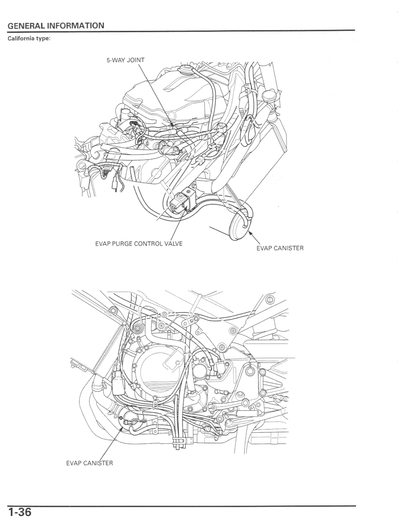
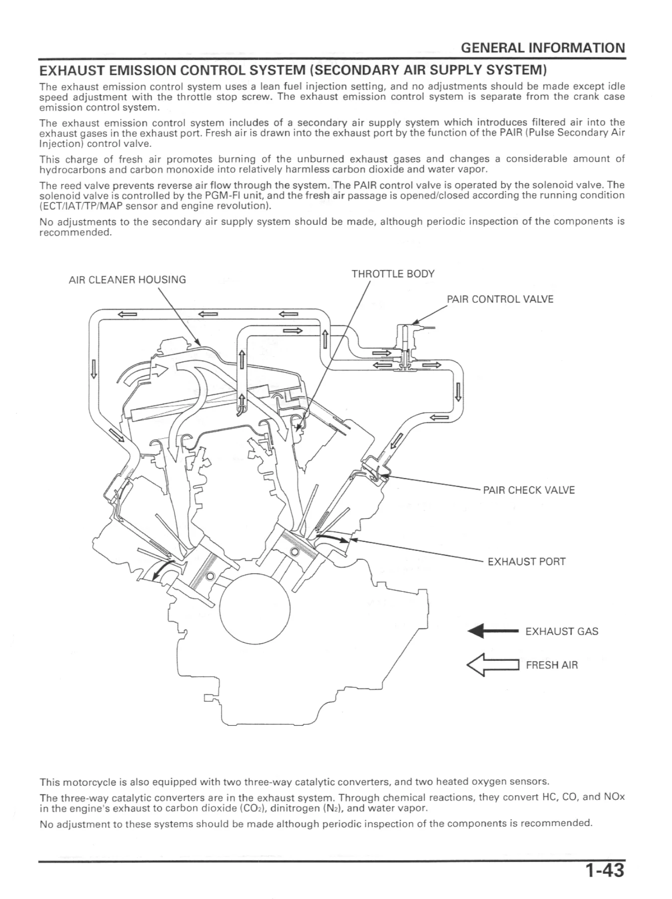
Maintenance procedures in Section 3 cover the fuel line, throttle operation, air cleaner, spark plug, valve clearance, engine oil and filter, engine idle speed, radiator coolant, cooling system, secondary air supply system, evaporative emission control system, drive chain, brake fluid, brake pad wear, brake system, brake light switch, headlight aim, clutch system, clutch fluid, side stand, suspension, nuts and bolts, wheels and tires, and steering head bearings. The maintenance schedule lists service intervals in miles and kilometers, with notes for severe duty and California-type models.
What This Manual Enables You to Do
With this 2002 Honda VFR800/A Interceptor service manual, you can confidently tackle:
- Complete engine tear-down and rebuild, including crankcase separation, crankshaft and piston service, and transmission inspection
- VTEC valve clearance inspection and adjustment with shim and valve lifter selection
- PGM-FI self-diagnosis and troubleshooting using MIL blink codes and diagnostic flow charts
- ABS problem code retrieval and component testing for wheel speed sensors and modulators
- Linked Brake System fluid replacement and air bleeding in the correct sequence
- Front and rear suspension service, including fork seal replacement, shock absorber service, and steering head bearing adjustment
- Drive chain inspection, adjustment, and replacement with the staked master link procedure
- Wiring diagram tracing and electrical troubleshooting for lights, meters, switches, and relays
- Routine maintenance scheduling and specification lookup for all service intervals
- Starter motor and starter clutch service, including one-way clutch inspection
- Fuel pump, injector, and fuel pressure regulator service
- Cooling system service, including water pump and thermostat inspection
Having the correct service procedures and torque specifications is essential when working on the VFR800. The VTEC system demands precise valve clearance adjustment and correct camshaft timing, and the linked brake system requires a specific bleeding sequence to function properly. This manual provides the exact figures and sequences the factory specifies, so you avoid guesswork and preventable damage to critical components.
IMAGES PREVIEW
Delivered as an instant PDF download, this 2002 Honda VFR800/A Interceptor service manual is ready to use immediately after purchase. There is no shipping, no waiting, and no physical book to keep track of. You can view it on any device, print only the pages you need for the job at hand, and keep the complete manual on hand for future service and repair work.

Reviews
There are no reviews yet.