
2004-2007 Yamaha WaveRunner FX High Output FX Cruiser 1100 Service Manual
Original price was: $34.95.$21.95Current price is: $21.95.
Complete Yamaha service and supplementary manual for the 2004-2007 WaveRunner FX High Output, FX Cruiser High Output, FX and FX Cruiser. Covers the 6B6 and 60E 1100cc four-stroke engines, jet pump, fuel injection, electrical system, hull and hood, plus full specifications and troubleshooting.
Description
2004-2007 Yamaha WaveRunner FX High Output FX Cruiser 1100 Service Manual
This is the service documentation set that Yamaha dealers and trained mechanics used on the WaveRunner FX High Output and FX Cruiser High Output personal watercraft, bundled with the supplementary manual that expands coverage to the FX and FX Cruiser models. Two editions are combined here: the original 2004 FX High Output / FX Cruiser High Output Service Manual and the December 2005 Supplementary Service Manual for the FX, FX Cruiser, FX High Output and FX Cruiser High Output. Between them, a technician gets a step-by-step reference for every major system on these 1100cc four-stroke WaveRunners, from routine periodic maintenance through complete engine, jet pump and electrical overhauls.
File Details
- Manual type: Service Manual + Supplementary Service Manual (combined)
- Brand: Yamaha
- Models covered: WaveRunner FX High Output, FX Cruiser High Output, FX, FX Cruiser
- Engine coverage: 6B6 (FX High Output / FX Cruiser High Output), 60E (FX / FX Cruiser)
- Language: English
- File format: PDF
- Main manual edition: 1st Edition, February 2004, LIT-18616-02-83, F1S-28197-1G-11
- Supplementary manual edition: 1st Edition, December 2005, LIT-18616-02-93, F1X-28197-1H-1X
- Page count: 500+ pages
Chapters Covered
The combined table of contents follows the Yamaha nine-chapter service format and mirrors how a technician actually works through a repair:
- General Information — identification numbers (primary I.D., engine serial, jet pump serial, H.I.N.), safety while working, fire prevention, ventilation, self-protection, parts/lubricants/sealants, good working practices, disassembly and assembly, special tools, measuring, removal and installation
- Specifications — general specifications, maintenance specifications (engine, jet pump unit, hull and hood, electrical), tightening torques (specified and general), cable and hose routing
- Periodic Inspection and Adjustment — maintenance interval chart, periodic service, control system (steering master, steering cable, throttle cable, QSTS cable, shift cable, trolling speed), fuel system (fuel line, water separator), power unit (valve clearance, engine oil level, oil change with oil changer, air filter element, spark plug inspection), electrical (battery), jet pump unit (impeller, water inlet strainer), bilge pump, drain plug, lubrication points
- Fuel System — arrangement of the throttle body components and couplers, fuel tank and fuel pump module, fuel injection system (throttle bodies, fuel injectors, bypass valve motor, throttle body synchronization, fuel pressure measurement, fuel hose disconnection and connection)
- Power Unit — engine unit removal and installation, oil filter, compression check, exhaust pipe 3, exhaust pipes 1 and 2, exhaust manifold, oil tank, oil pump, reduction drive gear, generator and starter motor, camshafts, cylinder head, valves and valve springs, crankcase, connecting rods and pistons, crankshaft, thermostat, cooling water hose
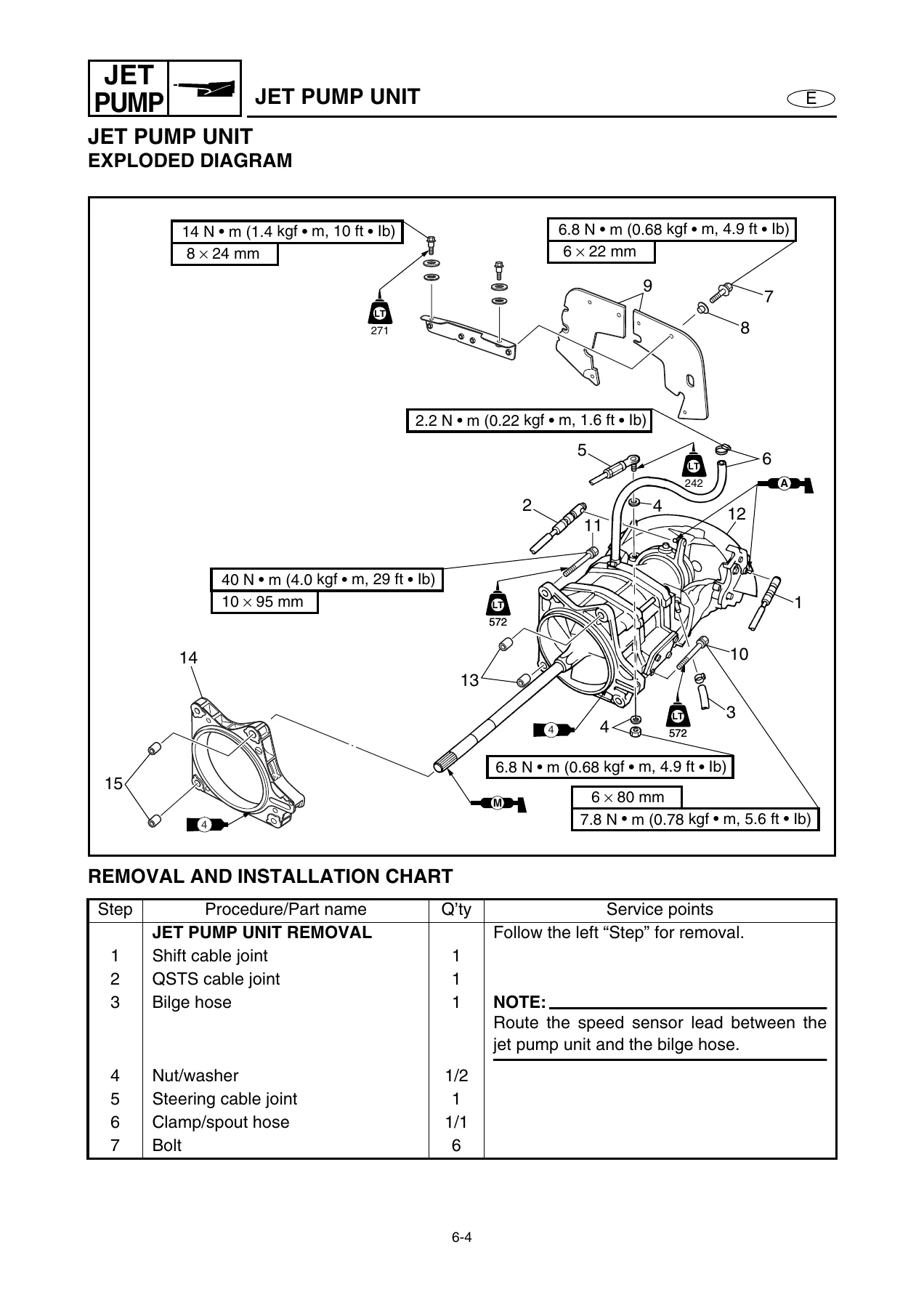
- Jet Pump Unit — intake grate, ride plate and intake duct, jet pump unit, reverse gate, jet thrust nozzle and nozzle ring, impeller duct and impeller housing, impeller duct and drive shaft, transom plate and hoses, bearing housing
- Electrical System — electrical components and box, electrical analysis (digital tester, low resistance measurement, peak voltage measurement, peak voltage adapter, test harness), ignition system, fuel control system, starting system, starter motor, charging system, electric bilge pump, off-throttle steering system, indication system, multifunction meter, remote control system
- Hull and Hood — handlebar, QSTS grip, steering master, remote control cables and speed sensor lead, front hood, steering console cover, hoses, shift lever, seats and hand grip, exhaust system, deck and hull, engine mount
- Trouble Analysis — introduction, hardware requirements, operating instructions, connecting the communication cable, trouble analysis chart, self-diagnosis
- Wiring Diagram — full fold-out style schematic with connector pin numbers, color codes and component index for FX, FX Cruiser, FX High Output and FX Cruiser High Output
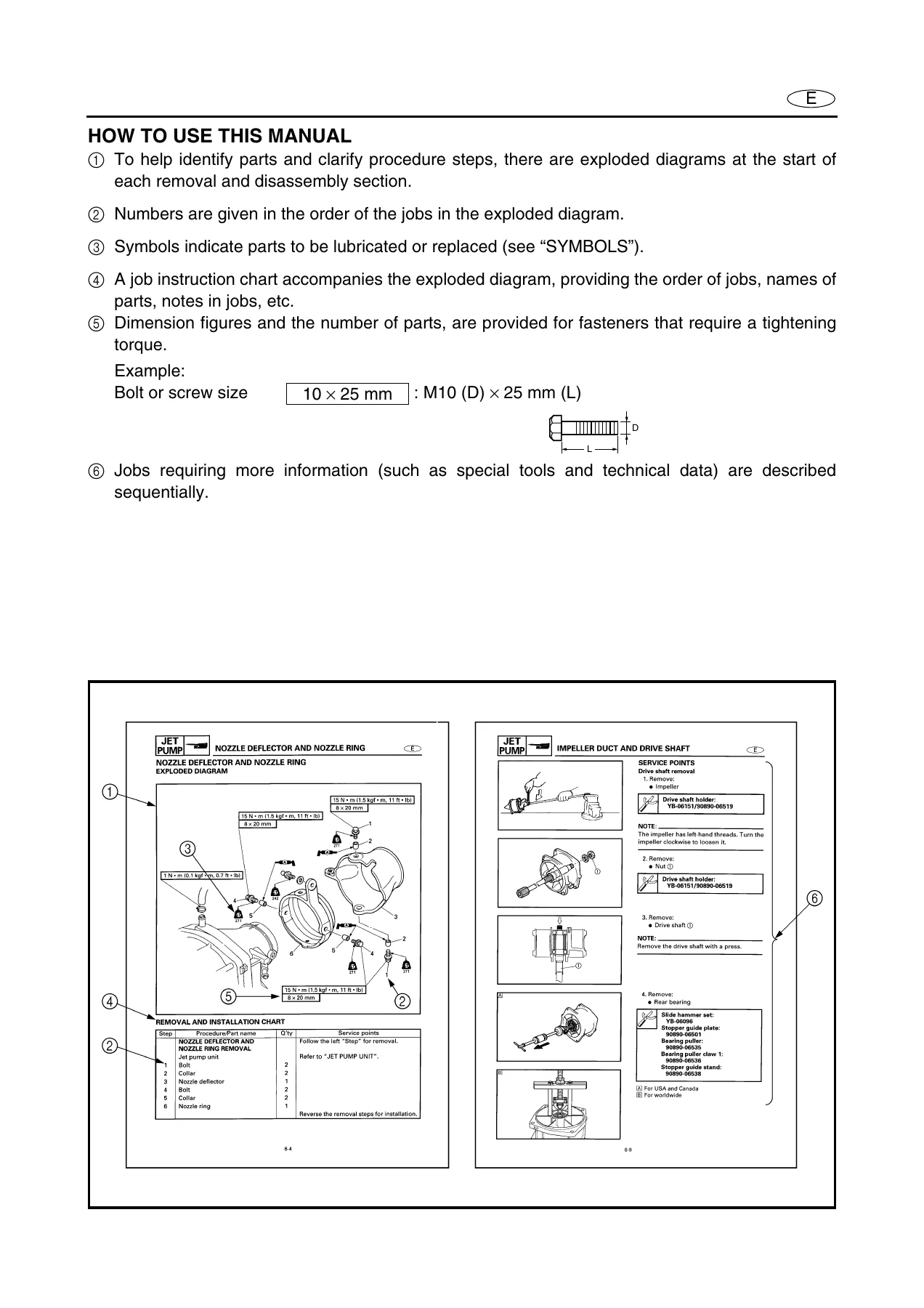
Across all nine chapters and the wiring diagram, the manual gives a working mechanic the complete sequence for any job on these WaveRunners: the order of disassembly, the torque value for every fastener, the clearance or wear limit for every inspected part, and the wiring colors and connector numbers needed to diagnose an electrical fault. Exploded diagrams open each removal and disassembly section, so the parts order, lubricant points and replacement items are visible before any tool is picked up. The troubleshooting chart cross-references symptom to system to chapter, and the self-diagnosis tables let the built-in multifunction meter display error codes without the Yamaha Diagnostic System if one is not on hand.
Engines, Serial Numbers and Models in This Manual
The main manual identifies the FX High Output and FX Cruiser High Output by hull code F1S and engine/jet code 6B6. The supplementary manual adds the FX and FX Cruiser, coded F1Y hull with 60E engine/jet. Yamaha’s published starting numbers are given so a technician can confirm which machine a manual page applies to: F1S 800101, F1X 800101, F1Y 800101, 6B6 1000001 (main manual) and 6B6 1018901, 60E 1017501 (supplementary). These identifications are printed inside the engine compartment, on the engine unit and on the intermediate housing, and the H.I.N. is on the aft deck plate — exactly where the manual tells you to look.
Engine and Driveline Specifications Included
The specifications section is deep enough to rebuild these engines without guesswork. The FX High Output and FX Cruiser High Output run the 6B6 four-stroke, inline four-cylinder, DOHC 1,052cc powerplant with a 76.0 × 58.0 mm bore and stroke, 11.9:1 compression and a 160 PS / 117.7 kW rating at 10,000 r/min. The FX and FX Cruiser run the 60E engine at 998cc with a 74.0 × 58.0 mm bore and stroke, 11.4:1 compression and 140 PS / 103 kW at 10,000 r/min. Both use a wet exhaust, dry sump lubrication and a single-stage axial-flow jet pump with a stainless steel 3-blade impeller, driven counterclockwise when viewed from the rear. Valve clearances, camshaft lobe dimensions, piston-to-cylinder clearances, ring end gaps, big-end oil clearances, crankshaft journal clearances and runout limits, cylinder head warpage limits, valve spring free lengths and installed lengths, bearing color codes for big-end and journal selection, and the throttle body and fuel pump data are all tabulated.
Fuel, Electrical and Diagnostic Coverage
The fuel system chapter covers the Mikuni throttle body arrangement, fuel tank and pump module, fuel sender, rollover and check valves, and the entire fuel injection system including injector resistance, bypass valve motor checks, throttle body synchronization, and fuel pressure measurement at 310–330 kPa. The electrical chapter supports real diagnosis: ECM output peak voltages at cranking, 2,000 and 3,500 r/min; pickup coil and lighting coil resistance and peak voltages; ignition coil primary and secondary resistance; rectifier/regulator output voltage; engine temperature sensor resistance at 20 °C and 100 °C; thermoswitch continuity temperatures for engine and exhaust; speed sensor output; throttle position sensor output voltage at trolling speed; cam position sensor output at three positions; fuel sender resistance; oil pressure switch continuity pressure; and the main and fuel pump relay test procedure. The self-diagnosis table lists the multifunction meter error codes 01, 13, 15, 18, 19, 23, 24, 29, 47, 48, 54, 55 and 63 with their meaning.
Tightening Torques and Service Values
Every assembly in the manual has a specified torque, and the values are grouped so they can be found quickly during a rebuild. Examples from the tightening torque tables include the cylinder head nuts at 20 N·m first stage plus 105°, 121° or 140° second-stage depending on the nut position; the cylinder head bolts at 10 N·m; the connecting rod nuts at 20 N·m plus 120°; the crankcase bolts staged at 7.8 N·m, then loosened completely, then 15 N·m plus 49 ± 5°; the flywheel magneto bolt at 75 N·m; the camshaft sprocket bolts at 24 N·m; the oil filter at 17 N·m; the fuel pump module nuts at 3.2 N·m then 6.4 N·m; the spark plug at 13 N·m; the jet pump drive shaft nut at 69 N·m; the impeller at 75 N·m; the intermediate housing bolts at 31 N·m; and the engine unit mount bolts at 17 N·m. A general torque chart covers standard M5 through M12 fasteners where no special value is listed.
Wiring Diagram
A full machine schematic is included with wire color codes (B, Br, G, Gy, L, O, P, R, W, Y and the two-tone combinations such as B/O, B/Y, R/Y, G/B, G/R, G/Y, L/B, L/R, P/W, Pu/B, Pu/G, Pu/R, Pu/Y, W/B, W/L, W/R, Y/B), connector pin numbering, and a component key that lists the ECM, main and fuel pump relay, starter relay, rectifier/regulator, noise filter, all sensors, all switches, multifunction meter, remote control unit, antenna, and the tachometer and entry box connections. This is the diagram a technician uses to trace a no-start, a warning indicator, or a remote control registration problem back to the offending circuit.
Who This Yamaha WaveRunner FX 1100 Service Manual Is For
This PDF is written for the mechanic who already understands basic mechanical and electrical procedures — the same audience Yamaha addressed when the manual was published — and for the experienced owner who is willing to work through a job in the proper order. It is not a beginner’s picture book; it is a dealer service reference with exploded views, step-by-step sequences, and the numbers needed to verify every measurement against the factory value. If you are chasing a hard-start, a rough idle, a low oil pressure warning, an overheating condition, a slipping impeller, a loose steering response, or an electrical fault on a 2004–2007 FX High Output, FX Cruiser High Output, FX or FX Cruiser, this manual gives you the diagnostic path and the specification to confirm it.
Why the Correct Procedures and Specifications Matter on a WaveRunner
Personal watercraft are unforgiving of wrong torque values and wrong clearances. Over-torquing a cylinder head nut, skipping the angle-controlled second stage on the crankcase, reusing a connecting rod bolt, or setting valve clearance cold with the wrong pad size can all end in a destroyed engine. The same applies to the jet pump — the impeller-to-housing clearance has a defined service limit, the drive shaft has a runout limit, and the bearing and oil seal installation depths are given to fractions of a millimetre. Using the factory sequence and the factory value is the difference between a repair that lasts a season and one that fails at the dock.
IMAGES PREVIEW
Instant PDF Delivery — No Shipping, Any Device
The Yamaha WaveRunner FX High Output FX Cruiser 1100 service manual and supplementary manual are delivered as a single downloadable PDF immediately after payment. There is no printed book to wait for, no shipping cost, and no region restriction. Read it on a laptop, tablet or phone in the workshop, print the pages you need for the job at hand, and keep the whole file on hand for the next repair. Everything shown here — the engine teardown, the jet pump service, the electrical diagnosis, the wiring schematic, the torque tables — is included in the file.
Reviews
There are no reviews yet.