2004 Buell Firebolt Xb9r Xb12r Service Manual – PDF DOWNLOAD
Original price was: $24.95.$14.95Current price is: $14.95.
LANGUAGE:ENGLISH
PAGES:500+
FILE TYPE:PDF
DOWNLOADABLE:YES
Description
2004 Buell Firebolt Xb9r Xb12r Service Manual
IMAGES PREVIEW OF THE MANUAL:
2004 BUELL FIREBOLT XB9R XB12R SERVICE MANUAL – PDF DOWNLOAD:
TABLE OF CONTENTS:
1.MAINTENANCE:
1.1 General 1-1
1.2 Fuel and Oil 1-5
1.3 Maintenance Schedule 1-6
1.4 Care of Molded-in-Color Body Panels 1-7
1.5 Battery Maintenance 1-8
1.6 Engine Lubrication System 1-11
1.7 Brake System Maintenance 1-14
1.8 Tires and Wheels 1-22
1.9 Clutch 1-23
1.10 Drive Belt System 1-26
1.11 Primary Chain 1-29
1.12 Suspension Damping Adjustments 1-31
1.13 Steering Head Bearings 1-35
1.14 Spark Plugs 1-36
1.15 Air Cleaner Filter 1-38
1.16 Throttle Cable and Idle Speed Adjustment 1-40
1.17 Interactive Exhaust Cable (XB12R) 1-41
1.18 Ignition Timing 1-43
1.19 Headlights 1-45
1.20 Throttle Position Sensor (TPS) 1-47
1.21 Storage 1-48
1.22 Troubleshooting 1-49
2.CHASSIS:
2.1 Specifications 2-1
2.2 Tire Specifications 2-5
2.3 Vehicle Identification Number 2-6
2.4 Wheels 2-7
2.5 Front Wheel 2-9
2.6 Rear Wheel 2-16
2.7 Checking Cast Rim Runout 2-20
2.8 Tires 2-21
2.9 Brake Pedal 2-25
2.10 Front Brake Master Cylinder 2-26
2.11 Front Brake Line 2-30
2.12 Front Brake Caliper 2-32
2.13 Rear Brake Master Cylinder 2-35
2.14 Rear Brake Line 2-39
2.15 Rear Brake Caliper 2-41
2.16 Front Fork 2-44
2.17 Fork Clamps, Upper and Lower 2-53
2.18 Steering Head Bearings 2-55
2.19 Swingarm and Brace 2-57
2.20 Front and Rear Isolator 2-61
2.21 Frame 2-62
2.22 Rear Shock Absorber 2-63
2.23 Throttle Control 2-65
2.24 Clutch Hand Lever 2-66
2.25 Headlight Assembly and Support Bracket 2-67
2.26 Fairing Support Bracket 2-70
2.27 Handlebars 2-72
2.28 Exhaust System 2-74
2.29 Footpeg, Heel Guard, and Mount 2-76
2.30 Sprocket Cover 2-78
2.31 Fenders 2-79
2.32 Belt Guards 2-80
2.33 Chin Fairing 2-82
2.34 Intake Cover Assembly 2-83
2.35 Air Scoops 2-84
2.36 Subframe Tail Assembly and Body Work 2-85
2.37 Front Fairing, Windshield, and Mirrors 2-89
2.38 Seat 2-90
2.39 Passenger Seat Lock 2-91
2.40 Sidestand 2-92
3.ENGINE:
3.1 Specifications 3-1
3.2 Engine 3-6
3.3 Engine Rotation for Service 3-8
3.4 Stripping Motorcycle for Engine Service 3-19
3.5 Engine Installation 3-29
3.6 Cylinder Head 3-45
3.7 Cylinder and Piston 3-63
3.8 Lubrication System 3-73
3.9 Oil Hose Routing and Oil Reservoir 3-74
3.10 Oil Pressure Indicator Switch 3-75
3.11 Crankcase Breathing System 3-76
3.12 Oiling System 3-78
3.13 Oil Pump 3-79
3.14 Oil Filter Mount 3-82
3.15 Hydraulic Lifters 3-83
3.16 Gearcase Cover And Cam Gears 3-85
3.17 Crankcase 3-90
4.FUEL SYSTEM:
4.1 Specifications 4-1
4.2 Dynamic Digital Fuel Injection 4-3
4.3 Diagnostic Introduction 4-5
4.4 Checking For Trouble Codes 4-6
4.5 Check Engine Lamp Diagnostics 4-8
4.6 Breakout Box 4-10
4.7 Wiggle Test 4-11
4.8 Initial Diagnostic Check 4-12
4.9 Check Engine Lamp Not Illuminated at Key ON 4-17
4.10 Check Engine Lamp On Continuously 4-20
4.11 Engine Cranks But Will Not Start 4-23
4.12 No ECM Power 4-28
4.13 Fuel Pressure Test 4-31
4.14 Idle Speed Control 4-36
4.15 Misfire 4-37
4.16 Trouble Code 11 4-41
4.17 Trouble Code 13 4-45
4.18 Trouble Code 14 4-50
4.19 Trouble Code 15 4-54
4.20 Trouble Code 16 4-58
4.21 Trouble Code 21 4-62
4.22 Trouble Codes 23 and 32 4-64
4.23 Trouble Codes 24 and 25 4-68
4.24 Trouble Code 33 4-71
4.25 Trouble Code 35 4-74
4.26 Trouble Code 36 4-77
4.27 Trouble Code 44 4-81
4.28 Trouble Codes 52, 53, 54 and 55 4-85
4.29 Trouble Code 56 4-86
4.30 Electronic Control Module 4-91
4.31 Cam Position Sensor and Rotor 4-93
4.32 Ignition Coil 4-97
4.33 Oxygen Sensor 4-99
4.34 Engine Temperature Sensor 4-100
4.35 Bank Angle Sensor 4-102
4.36 Intake Air Temperature Sensor 4-103
4.37 Throttle Position Sensor 4-104
5.ELECTRIC STARTER:
5.1 Specifications 5-1
5.2 Electric Starter System 5-2
5.3 Starting System Diagnosis 5-4
5.4 Starter Activation Circuits 5-8
5.5 Diagnostics/Troubleshooting 5-9
5.6 Starter System Testing 5-11
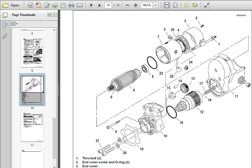
5.7 Starter 5-12
5.8 Starter Solenoid 5-21
6.DRIVE/TRANSMISSION:
6.1 Specifications 6-1
6.2 Primary Cover 6-3
6.3 Clutch Release Mechanism 6-7
6.4 Clutch 6-9
6.5 Primary Chain 6-16
6.6 Drive Belt System 6-21
6.7 Transmission 6-25
6.8 Case Disassembly For Transmission Removal 6-26
6.9 Transmission Disassembly 6-29
6.10 Transmission Assembly 6-36
6.11 Main Drive Gear 6-38
6.12 Transmission Right Case Bearings 6-41
6.13 Transmission Left Case Bearings 6-43
6.14 Transmission Installation 6-44
6.15 Shifter Shaft Installation 6-48
6.16 Transmission Sprocket 6-49
7.ELECTRICAL:
7.1 Specifications 7-1
7.2 Ignition System 7-3
7.3 Ignition/Headlight Key Switch 7-5
7.4 Spark Plug Cables 7-9
7.5 Starter Interlock 7-11
7.6 Interactive Exhaust System (XB12R) 7-18
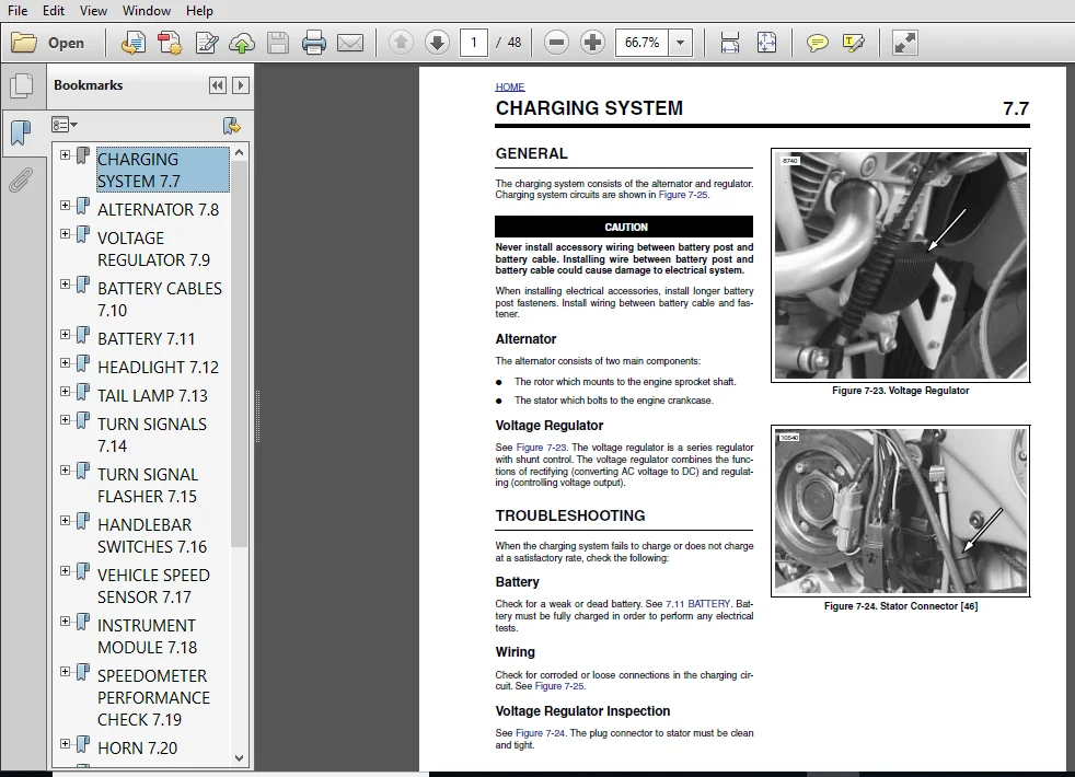
7.7 Charging System 7-23
7.8 Alternator 7-30
7.9 Voltage Regulator 7-32
7.10 Battery Cables 7-33
7.11 Battery 7-35
7.12 Headlight 7-41
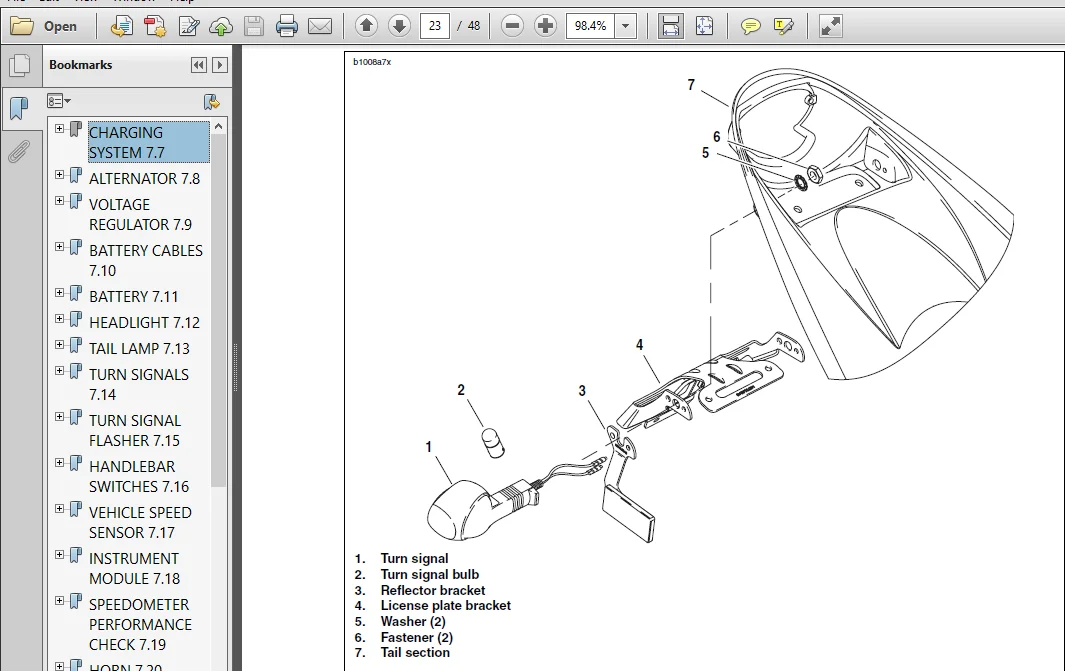
7.13 Tail Lamp 7-43
7.14 Turn Signals 7-44
7.15 Turn Signal Flasher 7-47
7.16 Handlebar Switches 7-48
7.17 Speedometer Sensor 7-50
7.18 Instrument Module 7-52
7.19 Speedometer Performance Check 7-53
7.20 Horn 7-58
7.21 Neutral Indicator Switch 7-60
7.22 Main Fuse and Fuses 7-61
7.23 Main Wire Harness 7-62
7.24 Interactive Exhaust Harness 7-67
7.25 Sprocket Cover Wiring 7-69
PLEASE NOTE:
- This is the same manual used by the DEALERSHIPS to SERVICE your vehicle.
- The manual can be all yours – Once payment is complete, you will be taken to the download page from where you can download the manual. All in 2-5 minutes time!!
- Need any other service / repair / parts manual, please feel free to contact us at heydownloadss @gmail.com . We may surprise you with a nice offer

Callum Ephraim –
How do I download it in Kindle?
Ricky Legend –
Did a great job providing needed manual. Small problem with initial order but customer service quickly addressed & fixed the issue. Very professional & HIGHLY suggest using this service again!!!