2005-2008 Porsche 911 Carrera 997-1 Workshop Manual – PDF DOWNLOAD
$30.95
2005-2008 Porsche 911 Carrera 997-1 Workshop Manual – PDF DOWNLOAD
Description
2005-2008 Porsche 911 Carrera 997-1 Workshop Manual – PDF DOWNLOAD
FILE DETAILS:
2005-2008 Porsche 911 Carrera 997-1 Workshop Manual – PDF DOWNLOAD
Language : English
Pages : 5222
Downloadable : Yes
File Type : PDF
IMAGES PREVIEW OF THE MANUAL:
TABLE OF CONTENTS:
2005-2008 Porsche 911 Carrera 997-1 Workshop Manual – PDF DOWNLOAD
01 01 IN Diagnostic system: reading out fault memory and activating systems – as of MY 2005 1
Tools 1
Performing vehicle handover 1
Reading out and erasing fault memory 2
10 01 TW Technical data, engine – as of MY 2005 5
Technical values 5
M96/05 and M97/01 engines 5
Engine design 6
Engine control 7
13 44 IN Mounting specification for connecting rod bolts – as of MY 2005 10
Tools 10
Securing connecting rod bolts 10
Securing connecting rod bolts 10
17 01 TW Technical data, lubrication system – as of MY 2005 13
Technical values 13
Engine lubrication 13
19 01 TW Technical data, cooling system – as of MY 2005 16
Technical values 16
Engine cooling 16
20 01 AW Basic safety instructions for working with the fuel system – as of MY 2005 19
Information 19
Safety instructions when working on fuel system 19
20 01 TW Technical data, fuel system – as of MY 2005 22
Technical values 22
Fuel supply 22
20 10 EN Emptying and filling the fuel tank – as of MY 2005 25
Tools 25
Preliminary work 25
Preliminary work 25
Emptying the fuel tank 26
Emptying the fuel tank 26
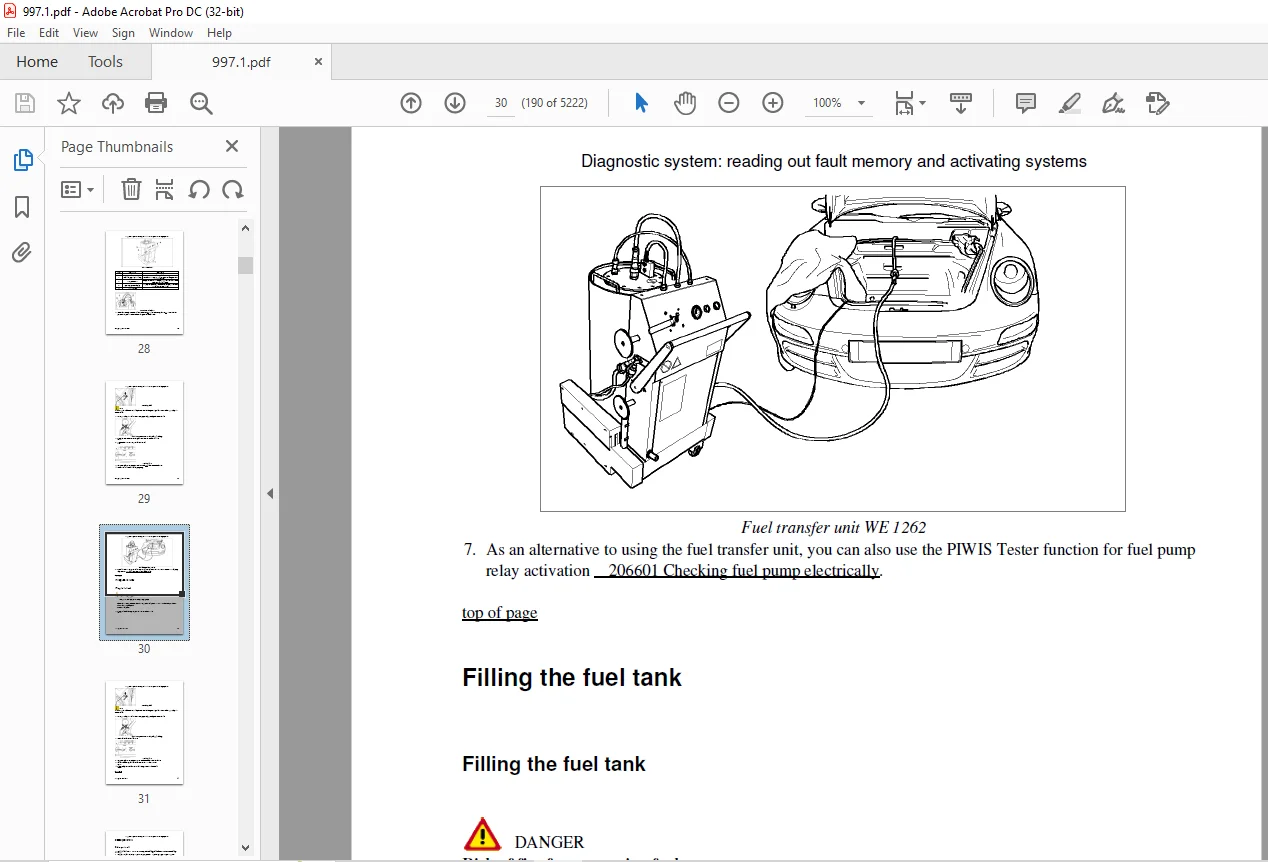
Filling the fuel tank 30
Filling the fuel tank 30
Subsequent work 32
Subsequent work 32
20 15 IN Calibrating fuel-level sensor system – as of MY 2005 34
Warning notes for calibrating fuel-level sensor system 34
Calibrating fuel-level sensor system, C4 35
Diagnostic system: reading out fault memory and activating systems
i
Table of Contents
20 15 IN Calibrating fuel-level sensor system – as of MY 2005 38
Warning notes for calibrating fuel-level sensor system 38
Calibrating fuel-level sensor system, C2 39
24 46 TW Technical data, intake system – as of MY 2005 42
Technical values 42
Intake system 42
Intake system tightening torques 42
26 01 TW Technical data, exhaust system – as of MY 2005 45
Technical values 45
Exhaust system and emission control 45
Exhaust system tightening torques 45
27 06 IN External power connection, jump lead starting – as of MY 2005 48
Preliminary work 48
Preliminary work for external power connection, jump lead starting 48
General warning notes 49
Warning notes for external power connection, jump lead starting 49
Information 49
External power connection 49
Jump lead starting 50
Subsequent work 51
Rework on external power connection, jump lead starting 51
27 06 IN Work instructions after disconnecting the battery – as of MY 2005 54
Disconnecting and connecting the battery 54
Disconnecting and connecting the battery 54
Effect of disconnection or total discharge of battery on electrical systems in the vehicle and
the precautions to be taken 55
Test drive after disconnecting battery 59
Effects of overvoltage on electrical and electronic systems during welding work and the
precautions to be taken 59
27 06 IN Electrical emergency release for lid – as of MY 2005 62
Electrical emergency release, front lid 62
34 35 TW Technical data, transmission – as of MY 2005 65
Technical values 65
Technical data 65
Transmission ratios 65
Filling capacities 65
34 35 TW Technical data, transmission – as of MY 2005 68
Technical values 68
Technical data 68
Transmission ratios 68
Filling capacities 68
Diagnostic system: reading out fault memory and activating systems
ii
Table of Contents
37 35 TW Technical data, automatic transmission – as of MY 2005 71
Technical values 71
Technical data 71
Transmission ratios 71
Filling capacities 71
37 35 TW Technical data, automatic transmission – as of MY 2005 74
Technical values 74
Technical data 74
Transmission ratios 74
Filling capacities 74
39 88 TW Technical data on front final drive – as of MY 2006 77
Technical values 77
Technical values 77
Transmission ratio 77
Filling capacities 77
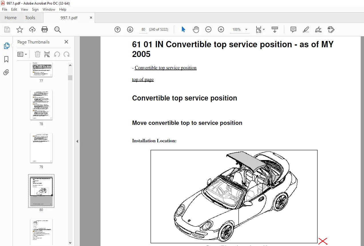
61 01 IN Convertible top service position – as of MY 2005 80
Convertible top service position 80
Move convertible top to service position 80
Ending convertible top service position 81
61 01 IN Overview of convertible-top components – as of MY 2005 85
Overview of convertible-top components 85
61 01 IN Diagram of convertible top – as of MY 2005 88
Diagram of convertible top 88
61 01 K2 Calibrating convertible top – as of MY 2005 91
Preliminary work 91
Preliminary work for calibration 91
General warning notes 91
Warning note on calibration 91
Calibrating convertible top 92
61 02 IN Assembly instructions for hardtop assembly fixture – as of MY 2005 94
Tools 94
Tools and materials 94
Tools and materials 94
Assembly instructions for hardtop assembly fixture 95
Making support cheeks 96
Making swivel arm 96
Fitting swivel and support cheeks on the basic plate 97
Fitting mounting points for the hardtop locking lever on the plate 98
Fitting horizontal banner arm and support on the base plate 99
Diagnostic system: reading out fault memory and activating systems
iii
Table of Contents
61 28 IN Care and cleaning of the convertible top – as of MY 2005 102
Care and cleaning of the convertible top 102
General information 102
Cleaning the convertible top 103
Care of convertible top 103
Care of convertible-top seals 103
64 12 IN Processing of Porsche 2-component window bonding agents – as of MY 2005 106
Pre-treatment of bonding surfaces 106
Pre-treating adhesive flanges on vehicle windows 106
Pre-treating adhesive flanges on vehicle body 107
Handling processing device 107
Double cartridge press 107
69 68 K2 Calibrating AWS control unit – as of MY 2005 113
Tools 113
Calibrating AWS control unit 113
Calibrating AWS control unit 113
87 43 IN Laying compressor/condenser line – as of MY 2005 118
Laying compressor/condenser line 118
87 45 IN Laying compressor/evaporator line – as of MY 2005 122
Laying compressor/evaporator line 122
94 15 IN Converting headlights for left/right-hand driving – as of MY 2005 126
Converting halogen headlights for left/right-hand driving 126
Converting Bi-Xenon headlights for left/right-hand driving 127
94 23 IN Bulb table and installation instructions – as of MY 2005 130
Bulb table 130
Bulb table 130
Installation instructions 131
Installation instructions for bulbs 131
97 72 IN Optical waveguide (LWL) – MOST bus – as of MY 2005 134
Tools 134
Optical waveguide (LWL) – MOST bus 134
Requirements when working with LWL 134
Storage, Packing, Transport 134
Installing the LWL in the vehicle 135
Repair 135
Push-on connector – dust boots 135
Control unit plug connector (wiring harness side) 136
Push-on connector – connection points 136
Optical fiber (LWL) – module 136
Optical waveguide variants 137
Removing and installing optical contacts on connector side 140
Diagnostic system: reading out fault memory and activating systems
iv
Table of Contents
97 72 IN Optical waveguide (LWL) – MOST bus – as of MY 2005
Installing optical contacts on connector side 141
Removing and installing optical contacts on socket side 141
Installing optical contacts on socket side 142
97 97 IN Connector – General information – as of MY 2005 146
Tools 146
Connector – General information 146
Procedure for releasing connectors that are difficult to move 149
01 01 00 Sales check – as of MY 2005 153
Sales check 153
03 24 00 Minor maintenance – as of MY 2005 157
Minor maintenance 157
03 26 00 Major maintenance – as of MY 2005 161
Major maintenance 161
03 35 00 On-board diagnosis (OBD) – as of MY 2005 165
Tools 165
Reading out and erasing fault memory 165
Reading out and erasing fault memory 165
03 60 00 Additional maintenance of drive belt – as of MY 2005 168
Additional maintenance of drive belt 168
03 81 00 Additional maintenance of spark plugs – as of MY 2005 171
Additional maintenance of spark plugs 171
Additional maintenance for spark plugs 171
03 83 00 Additional maintenance every 90,000 km/60 000 mls or every 6 years – as of MY 2005 174
Additional maintenance every 90,000 km/60 000 mls or every 6 years 174
03 88 00 Additional maintenance every 180,000 km/120 000 mls or every 12 years – as of MY 2005 177
Additional maintenance every 180,000 km/120 000 mls or every 12 years 177
Notes 177
Additional maintenance every 180,000 km/120,000 mls or every 12 years 177
Additional maintenance every 180,000 km/120,000 mls or every 12 years 177
03 88 00 Additional maintenance every 180,000 km/120 000 mls or every 12 years – as of MY 2005 180
Additional maintenance every 180,000 km/120 000 mls or every 12 years 180
Notes 180
Additional maintenance every 180,000 km/120,000 mls or every 12 years 180
Additional maintenance every 180,000 km/120,000 mls or every 12 years 180
Additional maintenance every 180,000 km/120,000 mls or every 12 years 181
Diagnostic system: reading out fault memory and activating systems
v
Table of Contents
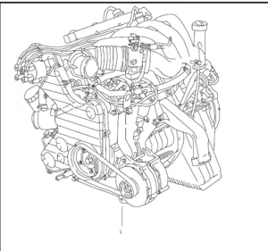
10 01 19 Removing and installing engine – as of MY 2005 183
Tools 183
Preliminary work for removing the engine 184
Preparations for removing the engine 185
Removing engine 186
Removing engine 186
Installing engine 201
Installing engine 201
Subsequent work for installation of engine 208
Installing engine – subsequent work 209
10 01 37 Disassembling and assembling engine – as of MY 2005 212
Tools 212
Preliminary work for disassembling engine 214
Preliminary work for disassembling engine 214
Component overview – engine 215
Component overview – engine 215
Disassembling engine – up to crankcase 217
Disassembling engine – up to crankcase 217
Assembling engine – from crankcase 231
Assembling engine – from crankcase 231
Assembling engine, subsequent work 237
Assembling engine, touching up 237
10 30 19 Removing and installing engine carrier – as of MY 2005 240
Preliminary work 240
Preliminary work 240
Removing engine carrier 240
Removing engine carrier 240
Installing engine carrier 242
Installing engine carrier 242
Subsequent work 242
Subsequent work 242
10 55 19 Removing and installing oil separator – as of MY 2005 245
Tools 245
Preliminary work 245
Preliminary work for removing oil separator 245
Removing oil separator 245
Removing oil separator 245
Installing oil separator 249
Installing oil separator 249
Subsequent work 251
Subsequent work for installing oil separator 251
13 10 20 Removing and installing pistons – as of MY 2005 254
Tools 254
Removing pistons, preliminary work 257
Diagnostic system: reading out fault memory and activating systems
vi
Table of Contents
13 10 20 Removing and installing pistons – as of MY 2005
Removing pistons, preliminary work 257
Removing pistons 257
Removing pistons 258
Disassembling pistons/connecting rods, cylinder 1-3 262
Disassembling pistons/connecting rods, cylinder 1-3 262
Assembling pistons/connecting rods, cylinder 1-3 263
Assembling pistons/connecting rods, cylinder 1-3 264
Piston markings 266
Piston markings 266
Installing pistons 267
Installing pistons 267
Installing pistons, touching up 280
Installing pistons, touching up 280
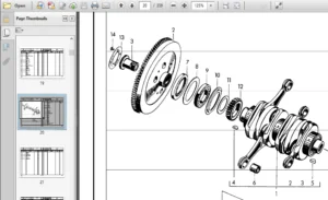
13 48 19 Removing and installing crankshaft – as of MY 2005 283
Tools 283
Removing crankshaft, preliminary work 284
Removing crankshaft, preliminary work 284
Removing crankshaft 287
Removing crankshaft 287
Installing crankshaft 290
Installing crankshaft 290
Installing crankshaft, touching up 294
Installing crankshaft, touching up 294
13 59 19 Removing and installing crankshaft sealing ring – Flywheel side – as of MY 2005 299
Tools 299
Preliminary work for crankshaft sealing ring on flywheel side 300
Preliminary work for crankshaft sealing ring on flywheel side 300
Removing crankshaft sealing ring on flywheel side 301
Removing crankshaft sealing ring on flywheel side 301
Installing crankshaft sealing ring on flywheel side 303
Installing crankshaft sealing ring (PTFE) on flywheel side 303
Subsequent work for crankshaft sealing ring on flywheel side 307
Subsequent work for crankshaft sealing ring on flywheel side 307
13 60 19 Removing and installing double-mass flywheel – as of MY 2005 310
Tools 310
Preliminary work 310
Preliminary work for double-mass flywheel 310
Removing double-mass flywheel – 3 8 l 310
Removing double-mass flywheel – 3 8 l 310
Installing double-mass flywheel 312
Installing double-mass flywheel 312
Subsequent work 312
Subsequent work for double-mass flywheel 312
Diagnostic system: reading out fault memory and activating systems
vii
Table of Contents
13 60 19 Removing and installing double-mass flywheel – as of MY 2005 315
Tools 315
Preliminary work 315
Preliminary work for double-mass flywheel 315
Removing double-mass flywheel – 3 6 l 315
Removing double-mass flywheel – 3 6 l 315
Installing double-mass flywheel 317
Installing double-mass flywheel 317
Subsequent work 317
Subsequent work for double-mass flywheel 317
13 63 19 Removing and installing drive plate for converter – as of MY 2005 320
Tools 320
Preliminary work for drive plate for converter 320
Preliminary work for drive plate for converter 320
Removing drive plate for converter 320
Removing drive plate for converter 320
Installing drive plate for converter 321
Installing drive plate for converter 321
Subsequent work for drive plate for converter 322
Subsequent work for drive plate for converter 322
13 74 19 Removing and installing crankshaft sealing ring – belt pulley side – as of MY 2005 324
Tools 324
Preliminary work for crankshaft sealing ring – belt pulley side 324
Preliminary work for crankshaft sealing ring – belt pulley side 324
Removing crankshaft sealing ring – belt pulley side 324
Removing the crankshaft sealing ring – belt pulley side 324
Installing crankshaft sealing ring – belt pulley side 326
Installing crankshaft sealing ring – belt pulley side 326
Subsequent work for crankshaft sealing ring – belt pulley side 327
Subsequent work for crankshaft sealing ring – belt pulley side 327
13 76 19 Removing and installing belt pulley/vibration damper – engine installed – as of MY 2005 330
Tools 330
Preliminary work – engine installed 330
Preliminary work for removing belt pulley/vibration damper – engine installed 330
Removing belt pulley/vibration damper – engine installed 331
Removing belt pulley (3 6 l) – engine installed 331
Installing belt pulley/vibration damper – engine installed 332
Installing belt pulley – 3 6 l engine installed 332
Subsequent work for installing belt pulley – engine installed 332
Subsequent work for installing belt pulley – engine installed 332
13 76 19 Removing and installing belt pulley/vibration damper – engine installed – as of MY 2005 335
Tools 335
Preliminary work – engine installed 335
Preliminary work for removing belt pulley/vibration damper – engine installed 335
Diagnostic system: reading out fault memory and activating systems
viii
Table of Contents
13 76 19 Removing and installing belt pulley/vibration damper – engine installed – as of MY 2005
Removing belt pulley/vibration damper – engine installed 336
Removing vibration damper (3 8 l) – engine installed 336
Installing belt pulley/vibration damper – engine installed 337
Installing vibration damper – 3 8 l engine installed 337
Subsequent work for installing belt pulley – engine installed 338
Subsequent work for installing belt pulley – engine installed 338
13 78 19 Removing and installing drive belt – as of MY 2005 341
Preliminary work 341
Preliminary work for removing drive belt 341
removing 341
Removing drive belt 341
Installing 342
Installing drive belt 342
Reworking 343
Work subsequent to installing drive belt 343
15 05 20 Removing and installing camshaft, adjusting timing – engine removed – as of MY 2005 345
Tools 345
Camshaft designation M96/05 346
Camshaft designation M96/05 346
Allocation of inlet camshaft adjustment device 347
Allocation of inlet camshaft adjustment device 347
Allocation of chain tensioners 348
Allocation of chain tensioners 348
Preliminary work for removing camshafts 349
Preliminary work for removing camshafts 349
Removing camshaft – engine removed 351
Removing camshafts – engine removed 351
Installing camshaft – engine removed 354
Installing camshafts, adjusting timing – engine removed 354
Subsequent work for installing camshafts 363
Subsequent work for installing camshafts 363
15 05 20 Removing and installing camshaft, adjusting timing – engine removed – as of MY 2005 367
Tools 367
Allocation of inlet camshaft adjustment device 368
Allocation of inlet camshaft adjustment device 368
Allocation of chain tensioners 369
Allocation of chain tensioners 369
Preliminary work for removing camshafts 370
Preliminary work for removing camshafts 370
Removing camshaft – engine removed 372
Removing camshafts – engine removed 372
Installing camshaft – engine removed 375
Installing camshafts, adjusting timing – engine removed 375
Subsequent work for installing camshafts 384
Diagnostic system: reading out fault memory and activating systems
ix
Table of Contents
15 05 20 Removing and installing camshaft, adjusting timing – engine removed – as of MY 2005
Subsequent work for installing camshafts 384
15 05 20 Removing and installing camshaft, adjusting timing – engine removed – as of MY 2005 388
Tools 388
Camshaft designation M97/01 389
Camshaft designation M97/01 389
Allocation of inlet camshaft adjustment device 390
Allocation of inlet camshaft adjustment device 390
Allocation of chain tensioners 391
Allocation of chain tensioners 391
Preliminary work for removing camshafts 392
Preliminary work for removing camshafts 392
Removing camshaft – engine removed 394
Removing camshafts – engine removed 394
Installing camshaft – engine removed 397
Installing camshafts, adjusting timing – engine removed 397
Subsequent work for installing camshafts 406
Subsequent work for installing camshafts 406
15 21 19 Removing and installing bearing cover for intermediate shaft – as of MY 2005 410
Tools 410
Preliminary work for bearing cover for intermediate shaft 411
Preliminary work for bearing cover for intermediate shaft 411
Removing bearing cover for intermediate shaft 411
Removing bearing cover for intermediate shaft 412
Installing bearing cover for intermediate shaft 415
Installing bearing cover for intermediate shaft 415
Subsequent work for bearing cover for intermediate shaft 417
Subsequent work for bearing cover for intermediate shaft 417
15 21 19 Removing and installing bearing cover for intermediate shaft – M97/01 – as of MY 2005 420
Tools 420
Preliminary work for bearing cover for intermediate shaft 421
Preliminary work for bearing cover for intermediate shaft 421
Removing bearing cover for intermediate shaft 422
Removing bearing cover for intermediate shaft – up to engine number 685 09 790 422
Removing bearing cover for intermediate shaft – from engine number 685 09 791 426
Installing bearing cover for intermediate shaft 431
Installing bearing cover for intermediate shaft – up to engine number 685 09 790 432
Installing bearing cover for intermediate shaft – from engine number 685 09 791 434
Subsequent work for bearing cover for intermediate shaft 437
Subsequent work for bearing cover for intermediate shaft 437
15 21 19 Removing and installing bearing cover for intermediate shaft – M96/05 – as of MY 2005 440
Tools 440
Removing bearing cover for intermediate shaft 441
Removing bearing cover for intermediate shaft – up to engine number 695 07 475 441
Diagnostic system: reading out fault memory and activating systems
x
Table of Contents
15 21 19 Removing and installing bearing cover for intermediate shaft – M96/05 – as of MY 2005
Removing bearing cover for intermediate shaft – from engine number 695 07 476 445
Installing bearing cover for intermediate shaft 451
Installing bearing cover for intermediate shaft – up to engine number 695 07 475 451
Installing bearing cover for intermediate shaft – from engine number 695 07 476 453
15 23 55 Replacing sealing ring for bearing cover for intermediate shaft – as of MY 2005 458
Preliminary work for bearing cover sealing ring 458
Preliminary work for bearing cover sealing ring 458
Replacing sealing ring for bearing cover for intermediate shaft 458
Replacing sealing ring for bearing cover for intermediate shaft 458
Subsequent work for bearing cover sealing ring 459
Subsequent work for bearing cover sealing ring 459
15 37 19 Removing and installing solenoid hydraulic valve (camshaft timing) – as of MY 2005 462
Tools 462
Removing hydraulic valve for camshaft timing 462
Removing hydraulic valve for camshaft timing 462
Installing hydraulic valve for camshaft timing 465
Installing hydraulic valve for camshaft timing 465
15 55 19 Removing and installing solenoid hydraulic valve (valve lift control) – as of MY 2005 470
Removing hydraulic valve for valve lift control 470
Removing hydraulic valve for valve lift control 470
Installing hydraulic valve for valve lift control 472
Installing hydraulic valve for valve lift control 472
15 70 19 Removing and installing cylinder head – engine removed – as of MY 2005 475
Tools 475
Preliminary work for removing cylinder head 475
Preliminary work for removing cylinder head 475
Removing cylinder head 477
Removing cylinder head 477
Installing cylinder head 478
Installing cylinder head 478
Subsequent work for installing cylinder head 480
Subsequent work for installing cylinder head 480
15 70 37 Disassembling and assembling cylinder head – as of MY 2005 484
Tools 484
Preliminary work for disassembling cylinder head 485
Preliminary work for disassembling cylinder head 485
Disassembling cylinder head 485
Disassembling cylinder head 485
Assembling cylinder head 489
Assembling cylinder head 489
Assembling cylinder head, touching up 491
Assembling cylinder head, touching up 491
Diagnostic system: reading out fault memory and activating systems
xi
Table of Contents
15 70 49 Machining the cylinder head – as of MY 2005 493
Preliminary work 493
Preliminary work for machining cylinder head 493
Machining the cylinder head 493
Machining the cylinder head 493
Subsequent work 494
Subsequent work for machining cylinder head 494
15 75 02 Checking valve guide (valve lateral play) – as of MY 2005 497
Tools 497
Preliminary work 497
Preliminary work 497
Checking valve guide (valve lateral play) 498
Checking valve guide (valve lateral play) 498
Subsequent work 499
Subsequent work 499
15 84 19 Removing and installing actuator for inlet camshaft – as of MY 2005 502
Tools 502
Removing actuator – camshaft removed 502
Removing actuator – camshaft removed 502
Installing actuator – camshaft removed 503
Installing actuator – camshaft removed 503
15 91 19 Removing and installing cylinder head cover – engine removed – as of MY 2005 507
Tools 507
Preliminary work for removing cylinder head cover 507
Preliminary work for removing cylinder head cover 507
Removing cylinder head cover – engine removed 507
Removing cylinder head cover – engine removed 507
Installing cylinder head cover – engine removed 510
Installing cylinder head cover – engine removed 511
Touch up for installing cylinder head cover 514
Touch up for installing cylinder head cover 514
17 01 01 Checking engine oil level – as of MY 2005 516
Checking engine oil level 516
Checking engine oil level 516
17 01 55 Engine oil and oil filter change – as of MY 2005 522
Tools 522
Draining engine oil 522
Draining engine oil 522
Changing oil filter 524
Changing oil filter 524
Refilling engine oil 526
Fill in engine oil 526
Reworking 527
Diagnostic system: reading out fault memory and activating systems
xii
Table of Contents
17 01 55 Engine oil and oil filter change – as of MY 2005
Subsequent work – topping up engine oil 527
17 04 19 Removing and installing oil-pressure sender – as of MY 2005 529
Tools 529
Removing oil-pressure sender 529
Removing oil-pressure sender 529
Installing oil-pressure sender 531
Installing oil-pressure sender 531
17 15 19 Removing and installing oil filler neck – as of MY 2005 534
Preliminary work 534
Preliminary work 534
Removing oil filler neck 535
Removing oil filler neck 536
Installing oil filler neck 536
Installing oil filler neck 536
Subsequent work 537
Subsequent work 537
19 01 01 Checking cooling system – as of MY 2005 541
Tools 541
checking 541
Coolant – check antifreeze and fluid level 541
Checking the cooling system for leaks 542
Cleaning the cooling air guides 543
Checking the antifreeze content using a refractometer 543
19 24 19 Removing and installing air guide – as of MY 2005 548
Preliminary work 548
Preliminary work for removing air guide 548
Removing air guide 548
Removing air guide for middle radiator 548
Removing air guide for side radiator 549
Installing air guide 550
Installing air guide for middle radiator 550
Installing air guide for side radiator 550
Subsequent work 552
Subsequent work for installing air guide 552
19 38 17 Draining and filling in coolant – as of MY 2005 554
Tools 554
Preliminary work 554
Preliminary work 554
Draining coolant 555
Draining coolant 555
Filling with coolant 558
Filling coolant (includes bleeding) 558
Diagnostic system: reading out fault memory and activating systems
xiii
Table of Contents
19 38 17 Draining and filling in coolant – as of MY 2005
Reworking 561
Subsequent work 561
19 40 19 Removing and installing reservoir for coolant – as of MY 2005 564
Tools 564
Preliminary work 564
Preliminary work 564
Removing reservoir for coolant 566
Removing reservoir for coolant 566
Installing reservoir for coolant 569
Installing reservoir for coolant 569
Subsequent work 570
Subsequent work 570
19 50 19 Removing and installing coolant pump – as of MY 2005 573
Preliminary work 573
Preliminary work 573
Removing coolant pump 574
Removing coolant pump 574
Installing coolant pump 575
Installing coolant pump 575
Subsequent work 576
Subsequent work 577
19 58 19 Removing and installing coolant regulator – as of MY 2005 580
Tools 580
Preliminary work 580
Preliminary work 580
Removing coolant regulator 581
Remove coolant regulator 581
Installing coolant regulator 582
Installing coolant regulator 583
Subsequent work 583
Subsequent work 583
19 70 19 Removing and installing radiator – as of MY 2005 586
Preliminary work 586
Preliminary work for removing radiator 586
Removing radiator 586
Removing radiator 586
Installing radiator 590
Installing radiator 590
Subsequent work 593
Subsequent work for installing radiator 594
Diagnostic system: reading out fault memory and activating systems
xiv
Table of Contents
19 80 19 Removing and installing middle radiator – as of MY 2005 596
Preliminary work 596
Preliminary work for removing middle radiator 596
Removing middle radiator 596
Removing middle radiator 596
Installing middle radiator 597
Installing middle radiator 597
Subsequent work 598
Subsequent work for installing middle radiator 598
20 02 01 Checking fuel pressure – as of MY 2005 601
Tools 601
Checking fuel pressure 601
Checking fuel pressure 601
20 07 19 Removing and installing filler neck – as of MY 2005 607
Tools 607
Preliminary work 607
Preliminary work 607
Removing filler neck 607
Removing filler neck 608
Installing filler neck 609
Installing filler neck 609
Subsequent work 610
Subsequent work 610
20 10 19 Removing and installing fuel tank – as of MY 2005 613
Tools 613
Preliminary work 613
Preliminary work – Carrera 4 613
Removing fuel tank 617
Removing fuel tank – Carrera 4 618
Installing fuel tank 620
Installing fuel tank – Carrera 4 620
Subsequent work 622
Subsequent work – Carrera 4 622
20 10 19 Removing and installing fuel tank – as of MY 2005 625
Tools 625
Preliminary work 626
Preliminary work – Carrera 2 626
Removing fuel tank 630
Removing fuel tank – Carrera 2 630
Installing fuel tank 633
Installing fuel tank – Carrera 2 633
Subsequent work 633
Subsequent work – Carrera 2 633
Diagnostic system: reading out fault memory and activating systems
xv
Table of Contents
20 25 19 Removing and installing carbon canister – as of MY 2005 637
Tools 637
Preliminary work for carbon canister 637
Preliminary work for carbon canister 637
Removing carbon canister 638
Removing carbon canister – RoW Version 638
Removing carbon canister – USA Version 639
Installing carbon canister 640
Installing carbon canister – RoW Version 640
Installing carbon canister – USA Version 641
Subsequent work for carbon canister 642
Subsequent work for carbon canister 642
20 66 01 Checking quantity delivered by fuel pump – as of MY 2005 646
Tools 646
Preliminary work for quantity delivered by fuel pump 646
Preliminary work for quantity delivered by fuel pump 646
Checking quantity delivered by fuel pump 647
Checking quantity delivered by fuel pump 647
Subsequent work for quantity delivered by fuel pump 650
Subsequent work for quantity delivered by fuel pump 650
20 66 19 Removing and installing fuel pump – as of MY 2005 653
Preliminary work 653
Preliminary work – Carrera 2 653
Removing fuel pump 653
Removing fuel pump – Carrera 2 653
Installing fuel pump 654
Installing fuel pump – Carrera 2 654
Subsequent work 654
Subsequent work – Carrera 2 655
20 66 19 Removing and installing fuel pump – as of MY 2005 657
Preliminary work 657
Preliminary work – Carrera 4 657
Removing fuel pump 657
Removing fuel pump – Carrera 4 657
Installing fuel pump 658
Installing fuel pump – Carrera 2 659
Installing fuel pump – Carrera 4 659
Subsequent work 660
Subsequent work – Carrera 4 660
20 66 19 Removing and installing fuel pump – as of MY 2005 663
Preliminary work 663
Preliminary work – Carrera 4 663
Removing fuel pump 663
Removing fuel pump – Carrera 4 663
Diagnostic system: reading out fault memory and activating systems
xvi
Table of Contents
20 66 19 Removing and installing fuel pump – as of MY 2005
Installing fuel pump 664
Installing fuel pump – Carrera 4 665
Subsequent work 665
Subsequent work – Carrera 4 665
24 24 19 Removing and installing air cleaner element – as of MY 2005 668
Preliminary work for removing air-cleaner element 668
Preliminary work for air cleaner element 668
Removing air-cleaner element 668
Removing air cleaner element 668
Installing air cleaner element 669
Installing air cleaner element 669
Subsequent work for installing air-cleaner element 670
Rework on air cleaner element 670
24 25 19 Removing and installing air cleaner housing – as of MY 2005 673
Removing air cleaner housing 673
Removing air cleaner housing 673
Installing air cleaner housing 674
Installing air cleaner housing 674
24 40 19 Removing and installing injection valves – as of MY 2005 678
Preliminary work 678
Preliminary work for removing injection valves 678
General warning notes 678
Danger from fuel 678
Hot engine components 679
Removing injection valves 679
Removing injection valves of cylinder bank 1-3 679
Removing injection valves of cylinder bank 4-6 682
Installing injection valves 684
Installing injection valves of cylinder bank 1-3 684
Installing injection valves of cylinder bank 4-6 686
Subsequent work 687
Work subsequent to installing injection valves 687
24 42 19 Removing and installing throttle body – as of MY 2005 690
Preliminary work 690
Preliminary work for removing throttle body 690
Removing throttle body 690
Removing throttle body 690
Installing throttle body 691
Installing throttle body 691
Subsequent work 691
Work subsequent to installing throttle body 691
Diagnostic system: reading out fault memory and activating systems
xvii
Table of Contents
24 46 19 Removing and installing intake distributor – as of MY 2005 694
Tools 694
Preliminary work 694
Preliminary work for removing intake distributor 694
General warning notes 694
Danger from Pentosin 695
Removing intake distributor, cylinder bank 1-3 695
Removing intake distributor, cylinder bank 1-3 695
Removing intake distributor, cylinder bank 1-3 698
Installing intake distributor, cylinder bank 1-3 698
Removing intake distributor, cylinder bank 4-6 701
Removing intake distributor, cylinder bank 4-6 701
Installing intake distributor, cylinder bank 4-6 705
Installing intake distributor, cylinder bank 4-6 705
Subsequent work 709
Subsequent work for installing intake distributor 709
24 69 19 Removing and installing oxygen sensor in front of catalytic converter – as of MY 2005 712
Tools 712
Preliminary work 712
Preliminary work for removing oxygen sensors in front of catalytic converter 712
Removing oxygen sensors in front of catalytic converter 713
Removing oxygen sensor in front of catalytic converter of cylinder bank 1-3 713
Removing oxygen sensor in front of catalytic converter of cylinder bank 4-6 713
Installing oxygen sensors in front of catalytic converter 714
Installing oxygen sensor in front of catalytic converter of cylinder bank 1-3 714
Installing oxygen sensor in front of catalytic converter of cylinder bank 4-6 715
Subsequent work 715
Subsequent work for installing oxygen sensors in front of catalytic converter 715
24 70 19 Removing and installing DME control module – as of MY 2005 718
Tools 718
Preliminary work 718
Preliminary work for DME control module in Cabriolet 718
General warning notes 719
General warning notes for control units 719
Removing DME control module 719
Removing DME control module in Cabriolet 719
Installing DME control module 720
Installing DME control module in cabriolet 720
Subsequent work 721
Subsequent work on DME control unit 721
Subsequent work for DME control module in Cabriolet 721
Programming DME control module 722
Programming new DME control module 722
Programming DME control module 723
Exhaust-gas standard 725
Diagnostic system: reading out fault memory and activating systems
xviii
Table of Contents
24 70 19 Removing and installing DME control module – as of MY 2005 728
Tools 728
Preliminary work 728
Subsequent work on DME control unit 728
Preliminary work for DME control module in Cabriolet 729
General warning notes 729
General warning notes for control units 729
Removing DME control module 730
Removing DME control module in Cabriolet 730
Installing DME control module 731
Installing DME control module in cabriolet 731
Subsequent work 731
Subsequent work on DME control unit 732
Subsequent work for DME control module in Cabriolet 732
Programming DME control module 732
Programming new DME control module 732
Programming DME control module 733
Exhaust-gas standard 735
24 70 19 Removing and installing DME control module – as of MY 2005 738
Tools 738
Preliminary work 738
Subsequent work on DME control unit 738
General warning notes 739
General warning notes for control units 739
Removing DME control module 739
Removing DME control module 739
Installing DME control module 741
Installing DME control module 741
Subsequent work 742
Subsequent work on DME control unit 742
Programming DME control module 742
Programming new DME control module 742
Programming DME control module 744
Exhaust-gas standard 745
24 73 19 Removing and installing oxygen sensor behind catalytic converter – as of MY 2005 748
Tools 748
Preliminary work 748
Preliminary work for removing oxygen sensor behind the catalytic converter 748
Removing oxygen sensor behind the catalytic converter 749
Removing oxygen sensor behind catalytic converter of cylinder bank 1-3 749
Removing oxygen sensor behind catalytic converter of cylinder bank 4-6 750
Installing oxygen sensor behind the catalytic converter 750
Installing oxygen sensor behind catalytic converter of cylinder bank 1-3 751
Installing oxygen sensor behind catalytic converter of cylinder bank 4-6 751
Subsequent work 752
Subsequent work for installing oxygen sensor behind the catalytic converter 752
Diagnostic system: reading out fault memory and activating systems
xix
Table of Contents
24 74 19 Removing and installing tuning pipe – as of MY 2005 754
Preliminary work 754
Preliminary work for removing tuning pipe 754
Removing tuning pipe 754
Removing tuning pipe 754
Installing tuning pipe 756
Installing tuning pipe 756
Subsequent work 757
Work subsequent to installing tuning pipe 757
26 10 19 Removing and installing exhaust manifold – as of MY 2005 760
Removing exhaust manifold 760
Removing exhaust manifold 760
Installing exhaust manifold 762
Installing exhaust manifold 762
26 33 19 Removing and installing rear silencer – as of MY 2005 766
Tools 766
Preliminary work 766
Preliminary work 766
Removing rear silencer 767
Removing rear silencer 767
Installing rear silencer 769
Installing rear silencer 769
Subsequent work 770
Subsequent work 770
26 34 19 Removing and installing tailpipe – as of MY 2005 773
Removing tailpipe – 3 6 l 773
Removing tailpipe – M 96/05 (3 6 l) 773
Installing tailpipe – 3 6 l 773
Installing tailpipe – 3 6 l 773
26 34 19 Removing and installing tailpipe – as of MY 2005 777
Removing tailpipe -3 8 l 777
Removing tailpipe – 3 8 l 777
Installing tailpipe -3 8 l 777
Installing tailpipe – 3 8 l 777
26 65 19 Removing and installing secondary air pump – as of MY 2005 781
Preliminary work 781
Preliminary work for removing secondary air pump 781
Removing secondary air pump 781
Removing secondary air pump 781
Installing secondary air pump 782
Installing secondary air pump 783
Subsequent work 784
Work subsequent to installing secondary air pump 784
Diagnostic system: reading out fault memory and activating systems
xx
Table of Contents
26 73 19 Removing and installing catalytic converter – as of MY 2005 787
Preliminary work 787
Preliminary work 787
Removing catalytic converter 788
Removing catalytic converter 788
Installing catalytic converter 790
Installing catalytic converter 790
Subsequent work 791
Subsequent work 791
27 06 01 Battery trickle charge – as of MY 2005 794
Preliminary work 794
General warning notes 794
Tools and materials 794
Checking battery charging condition with battery tester 794
Reworking 795
27 06 19 Removing and installing battery – as of MY 2005 797
Removing battery 797
Removing battery 797
Installing battery 798
Installing battery 798
Subsequent work 799
Subsequent work – battery 800
27 12 19 Removing and installing battery cover – as of MY 2005 802
Removing battery cover 802
Removing battery cover 802
Installing battery cover 802
Installing battery cover 803
Subsequent work 803
Reworking if cowl panel cover deformed 803
27 22 19 Removing and installing three-phase generator – as of MY 2005 807
Preliminary work 807
Preliminary work – three-phase generator 807
Removing three-phase generator 807
Removing three-phase generator 807
Installing three-phase generator 809
Installing three-phase generator 809
Subsequent work 811
Subsequent work – three-phase generator 811
27 60 19 Removing and installing starter – as of MY 2005 814
Preliminary work 814
Preliminary work – starter 814
Removing starter 814
Removing starter 814
Diagnostic system: reading out fault memory and activating systems
xxi
Table of Contents
27 60 19 Removing and installing starter – as of MY 2005
Installing starter 816
Installing starter 816
Subsequent work 817
Subsequent work – starter 817
28 04 19 Removing and installing ignition switch – as of MY 2005 820
Tools 820
Removing ignition switch 820
Removing ignition switch 820
Installing ignition switch 821
Installing ignition switch 822
Information 822
Emergency operation of the ignition key lock 822
28 70 20 Removing and installing spark plugs – as of MY 2005 825
Tools 825
Preliminary work 825
Preliminary work 826
Removing 826
Removing spark plugs 826
Installing 827
Installing spark plugs 827
Subsequent work 827
Reworking 828
28 72 19 Removing and installing knock sensor – as of MY 2005 830
Preliminary work 830
Preliminary work for removing knock sensor 830
Removing knock sensor 830
Removing knock sensor, cylinder bank 1-3 830
Removing knock sensor, cylinder bank 4-6 831
Installing knock sensor 831
Installing knock sensor, cylinder bank 1 -3 831
Installing knock sensor, cylinder bank 4 -6 832
Subsequent work 832
Work subsequent to installing knock sensor 832
30 01 07 Bleeding the clutch system – as of MY 2005 835
Information 835
Important notes on bleeding 835
Filling/bleeding 835
30 05 01 Checking clutch pedal (end position) – as of MY 2005 839
Clutch pedal: checking play and pedal end position 839
Checking clutch free play 839
Clutch: Checking pedal end position (pedal return/return force) 839
Diagnostic system: reading out fault memory and activating systems
xxii
Table of Contents
30 05 19 Removing and installing the clutch pedal – as of MY 2005 842
842
Preliminary work 842
843
General warning notes 843
843
Technical values 843
844
Removing 844
845
Installing 845
847
Subsequent work 847
30 30 19 Removing and installing clutch slave cylinder – as of MY 2005 850
Removing and installing 850
Removing clutch slave cylinder 850
Installing clutch slave cylinder 850
30 47 19 Removing and installing guide sleeve – as of MY 2005 854
Preliminary work 854
Preliminary work 854
Removing guide sleeve 854
Removing guide sleeve 854
Installing guide sleeve 855
Installing guide sleeve 855
Subsequent work 856
Subsequent work 856
30 50 19 Removing and installing clutch – as of MY 2005 859
Tools 859
Preliminary work 859
Preliminary work 859
Removing clutch 860
Removing clutch 860
Removing clutch 860
Installing clutch 861
Installing clutch 861
Reworking 862
Subsequent work 862
30 56 01 Checking clutch plate for wear – as of MY 2005 865
Preliminary work 865
Preliminary work 865
Checking clutch plate for wear 865
Checking clutch plate for wear 865
Subsequent work 866
Subsequent work 866
Diagnostic system: reading out fault memory and activating systems
xxiii
Table of Contents
32 43 19 Removing and installing converter housing – as of MY 2005 869
Preliminary work 869
Preliminary work 869
Removing converter housing 870
Removing converter housing 870
Installing converter housing 870
Installing converter housing 870
Subsequent work 872
Subsequent work 872
32 47 19 Removing and installing torque converter sealing ring – as of MY 2005 874
Tools 874
Information 874
Notes 875
Preliminary work 875
Preliminary work 875
Removing the torque converter 875
Removing the torque converter sealing ring 876
Removing the torque-converter sealing ring 876
Installing the torque converter sealing ring 876
Installing the torque-converter sealing ring 877
Subsequent work 877
Installing the torque converter 877
Reworking 878
32 50 19 Removing and installing torque converter – as of MY 2005 881
Tools 881
Information 881
Notes 881
Preliminary work 882
Preliminary work 882
Removing torque converter 882
Removing the torque converter 882
Installing torque converter 883
Installing the torque converter 883
Subsequent work 884
Reworking 884
34 01 35 Checking and topping up transmission oil – as of MY 2005 886
Information 886
Notes 886
Preliminary work 886
Preliminary work 886
Checking and topping up transmission oil 886
Checking and topping up transmission oil 887
Subsequent work 887
Reworking 887
Diagnostic system: reading out fault memory and activating systems
xxiv
Table of Contents
34 01 55 Changing transmission oil – as of MY 2005 890
Information 890
Notes 890
Technical values 890
Filling capacities 890
Preliminary work 891
Preliminary work 891
Draining transmission oil 891
Draining transmission oil 891
Refilling transmission oil 892
Filling in transmission oil 892
Subsequent work 892
Reworking 892
34 04 19 Removing and installing shift lever knob – as of MY 2005 895
Removing shift lever knob 895
Removing shift-lever knob 895
Installing shift lever knob 896
Installing shift-lever knob 896
34 08 19 Removing and installing shift console – as of MY 2005 900
Tools 900
Preliminary work 900
Preliminary work 900
Removing shift console 901
Removing gearshift bracket 901
Installing shift console 902
Installing gearshift bracket 903
Subsequent work 905
Subsequent work 905
34 12 19 Removing and installing shift and selector cables – as of MY 2005 908
Tools 908
Preliminary work 908
Preliminary work 908
Removing shift and selector cables 908
Detaching shift and selector cables at transmission 908
Detaching shift and selector cables inside vehicle 909
Installing shift and selector cables 910
Fastening shift and select cables to the transmission 910
Securing shift and selector cables inside vehicle 912
Subsequent work 913
Subsequent work 913
34 35 19 Removing and installing transmission – as of MY 2005 916
Tools 916
Preliminary work 916
Preliminary work 916
Diagnostic system: reading out fault memory and activating systems
xxv
Table of Contents
34 35 19 Removing and installing transmission – as of MY 2005
Removing transmission 916
Dismantling 916
Removing transmission 919
Installing transmission 920
Installing transmission 920
Assembly work 923
Subsequent work 925
Subsequent work 925
34 35 19 Removing and installing transmission – as of MY 2005 928
Tools 928
Preliminary work 928
Preliminary work 928
Removing transmission 928
Dismantling 928
Removing transmission 931
Installing transmission 932
Installing transmission 932
Assembly work 935
Subsequent work 937
Subsequent work 937
34 35 27 Removing and refitting transmission – as of MY 2005 940
Preliminary work 940
Preliminary work 940
Removing transmission 940
Removing transmission 940
Refitting transmission 941
Refitting transmission 941
Subsequent work 943
Subsequent work 943
35 50 19 Removing and installing sealing ring for input shaft – as of MY 2005 945
Tools 945
Preliminary work 945
Preliminary work 946
Removing sealing ring for input shaft 946
Removing sealing ring for drive shaft 946
Installing sealing ring for input shaft 947
Installing sealing ring for input shaft 947
Subsequent work 949
Subsequent work 949
37 02 35 Checking and topping up the ATF – as of MY 2005 951
Tools 951
Information 951
Notes 951
Diagnostic system: reading out fault memory and activating systems
xxvi
Table of Contents
37 02 35 Checking and topping up the ATF – as of MY 2005
Preliminary work 952
Preliminary work 952
Checking and topping up the ATF 953
Checking and topping up the ATF 953
Reworking 954
Reworking 954
37 02 55 Changing ATF – as of MY 2005 956
Tools 956
Information 956
Notes 956
Technical values 957
Filling capacities 957
Preliminary work 957
Preliminary work 957
Changing ATF 957
Draining ATF 957
Topping up ATF 958
Checking and topping up the ATF 960
Subsequent work 960
Reworking 960
37 04 19 Removing and installing selector knob – as of MY 2005 963
Removing selector knob 963
Removing selector knob 963
Installing selector knob 964
Installing selector knob 964
37 08 19 Removing and installing selector support – as of MY 2005 967
Preliminary work 967
Preliminary work 967
Removing selector support 967
Removing selector frame 967
Installing selector support 969
Installing selector frame 969
Subsequent work 971
Subsequent work 971
37 15 19 Removing and installing selector lever cable – as of MY 2005 974
Preliminary work 974
Preliminary work 974
Removing selector lever cable 974
Removing selector lever cable from transmission 974
Detaching selector lever cable inside vehicle 975
Installing selector lever cable 976
Fastening selector lever cable on transmission 976
Securing selector lever cable inside vehicle 978
Diagnostic system: reading out fault memory and activating systems
xxvii
Table of Contents
37 15 19 Removing and installing selector lever cable – as of MY 2005
Subsequent work 979
Subsequent work 979
37 18 20 Removing and installing Tiptronic rocker switch – as of MY 2005 982
Preliminary work 982
Preliminary work 982
Removing Tiptronic rocker switch 982
Removing Tiptronic rocker switch 982
Installing Tiptronic rocker switch 983
Installing Tiptronic rocker switch 983
Subsequent work 984
Subsequent work 984
37 30 19 Removing and installing the Tiptronic control module – as of MY 2005 987
Tools 987
Preliminary work 987
Preliminary work for Tiptronic control module (also referred to generally as control unit
below) 987
General warning notes 988
General warning notes for control units 988
Removing Tiptronic control module 988
Removing Tiptronic control module (also referred to generally as control unit below) 988
Installing Tiptronic control module 991
Installing Tiptronic control unit (also referred to generally as control unit below) 991
Subsequent work 993
Subsequent work for Tiptronic control module (also referred to generally as control unit
below) 993
Programming Tiptronic control module 993
Reading out from and writing in to the Tiptronic control unit (also referred to generally as
control unit below) 993
Coding Tiptronic control module 994
Coding Tiptronic control unit 994
37 35 27 Removing and refitting the automatic transmission – as of MY 2005 998
Tools 998
Information 999
Notes 999
Preliminary work 999
Preliminary work 999
Removing the automatic transmission 999
Disassembly work 1000
Releasing torque converter 1001
Removing the automatic transmission 1002
Refitting the automatic transmission 1003
Refitting the automatic transmission 1003
Fastening torque converter 1003
Assembly work 1004
Diagnostic system: reading out fault memory and activating systems
xxviii
Table of Contents
37 35 27 Removing and refitting the automatic transmission – as of MY 2005
Reworking 1005
Reworking 1006
37 55 19 Removing and installing ATF pan – as of MY 2005 1008
Tools 1008
Information 1008
Notes 1008
Technical values 1009
Filling capacities 1009
Preliminary work 1009
Preliminary work 1009
Draining ATF 1009
Removing ATF pan 1010
Removing ATF pan 1010
Installing ATF pan 1011
Installing ATF pan 1012
Reworking 1012
Topping up ATF 1012
Checking and topping up the ATF 1014
Reworking 1015
37 58 55 Replacing ATF filter – as of MY 2005 1017
Tools 1017
Notes 1017
Notes 1017
Filling capacities 1018
Filling capacities 1018
Preliminary work 1018
Preliminary work 1018
Draining ATF 1018
Removing ATF pan 1019
Removing ATF filter 1020
Removing ATF filter 1020
Installing ATF filter 1021
Installing ATF filter 1021
Subsequent work 1021
Installing ATF pan 1022
Topping up ATF 1022
Checking and topping up the ATF 1024
Reworking 1024
38 60 19 Removing and installing ATF cooler – as of MY 2005 1027
Tools 1027
Preliminary work 1027
Preliminary work 1027
Removing ATF cooler 1028
Removing ATF cooler 1028
Diagnostic system: reading out fault memory and activating systems
xxix
Table of Contents
38 60 19 Removing and installing ATF cooler – as of MY 2005
Installing ATF cooler 1029
Installing ATF cooler 1029
Subsequent work 1030
Subsequent work 1030
38 77 19 Removing and installing electrohydraulic control unit – as of MY 2005 1034
Tools 1034
Information 1034
Notes 1035
Technical values 1035
Filling capacities 1035
Preliminary work 1035
Preliminary work 1035
Draining ATF 1036
Removing the electrohydraulic control unit 1036
Dismantling 1036
Removing the electrohydraulic control unit 1038
Installing the electrohydraulic control unit 1039
Installing the electrohydraulic control unit 1040
Assembly work 1041
Subsequent work 1043
Topping up ATF 1043
Checking and topping up the ATF 1045
Reworking 1045
38 77 37 Disassembling and assembling electrohydraulic control unit – as of MY 2005 1048
Preliminary work 1048
Preliminary work 1048
Disassembling electrohydraulic control unit 1048
Overview 1048
Disconnecting hydraulic and electrical control unit 1049
Removing solenoid and control valve 1049
Installing solenoid and control valve 1050
Reassembling the hydraulic and electrical control unit 1050
Subsequent work 1050
Reworking 1050
39 02 19 Removing and installing cardan shaft – as of MY 2006 1053
Tools 1053
Preliminary work 1053
Preliminary work 1053
Removing cardan shaft 1053
Removing cardan shaft 1053
Installing cardan shaft 1055
Installing cardan shaft 1055
Subsequent work 1057
Subsequent work 1058
Diagnostic system: reading out fault memory and activating systems
xxx
Table of Contents
39 22 19 Removing and installing sealing ring for right-hand halfshaft flange – as of MY 2005 1060
Tools 1060
Preliminary work 1060
Preliminary work 1060
Removing sealing ring for halfshaft flange 1060
Removing sealing ring for halfshaft flange 1060
Installing sealing ring for halfshaft flange 1061
Installing sealing ring for halfshaft flange 1061
Subsequent work 1062
Subsequent work 1062
39 22 19 Removing and installing sealing ring for left halfshaft flange – as of MY 2005 1065
Tools 1065
Preliminary work 1065
Preliminary work 1065
Removing sealing ring for halfshaft flange 1065
Removing sealing ring for halfshaft flange 1065
Installing sealing ring for halfshaft flange 1066
Installing sealing ring for halfshaft flange 1066
Subsequent work 1067
Subsequent work 1067
39 22 19 Removing and installing sealing ring for short halfshaft flange – as of MY 2005 1070
Tools 1070
Preliminary work 1070
Preliminary work 1071
Removing sealing ring for short halfshaft flange 1071
Removing sealing ring for short halfshaft flange 1071
Installing sealing ring for halfshaft flange 1071
Installing sealing ring for short halfshaft flange 1071
Subsequent work 1072
Subsequent work 1072
39 25 19 Removing and installing right halfshaft flange – as of MY 2005 1075
Preliminary work 1075
Preliminary work 1075
Removing halfshaft flange 1075
Removing halfshaft flange 1075
Installing halfshaft flange 1076
Installing halfshaft flange 1076
Subsequent work 1077
Subsequent work 1077
39 25 19 Removing and installing left halfshaft flange – as of MY 2005 1080
Preliminary work 1080
Preliminary work 1080
Removing halfshaft flange 1080
Removing halfshaft flange 1080
Diagnostic system: reading out fault memory and activating systems
xxxi
Table of Contents
39 25 19 Removing and installing left halfshaft flange – as of MY 2005
Installing halfshaft flange 1081
Installing halfshaft flange 1081
Subsequent work 1082
Subsequent work 1082
39 25 19 Removing and installing short halfshaft flange – as of MY 2005 1084
Preliminary work 1084
Preliminary work 1084
Removing short halfshaft flange 1084
Removing short halfshaft flange 1084
Installing short halfshaft flange 1085
Installing short halfshaft flange 1085
Subsequent work 1087
Subsequent work 1087
39 25 19 Removing and installing long halfshaft flange – as of MY 2005 1090
Tools 1090
Preliminary work 1090
Preliminary work 1090
Removing long halfshaft flange 1090
Removing long halfshaft flange 1090
Installing long halfshaft flange 1091
Installing long halfshaft flange 1091
Subsequent work 1093
Subsequent work 1093
39 58 19 Removing and installing cover for front final drive – as of MY 2006 1095
Tools 1095
Preliminary work 1095
Preliminary work 1095
Removing cover for front final drive 1095
Removing cover for front final drive 1096
Installing cover for front final drive 1096
Installing cover for front final drive 1096
Subsequent work 1097
Subsequent work 1097
39 59 19 Removing and installing sealing ring for front halfshaft flange – as of MY 2006 1100
Tools 1100
Preliminary work 1100
Preliminary work 1100
Removing sealing ring for front halfshaft flange 1100
Removing sealing ring for front halfshaft flange 1100
Installing sealing ring for front halfshaft flange 1101
Installing sealing ring for front halfshaft flange 1101
Subsequent work 1103
Subsequent work 1103
Diagnostic system: reading out fault memory and activating systems
xxxii
Table of Contents
39 60 01 Checking operation of the viscous clutch – as of MY 2006 1105
Tools 1105
Checking operation of the viscous clutch 1105
Information 1105
Checking operation of the viscous clutch 1106
39 60 19 Removing and installing the viscous clutch – as of MY 2006 1109
Tools 1109
Preliminary work 1109
Preliminary work 1109
Removing the viscous clutch 1110
Removing the viscous clutch 1110
Installing the viscous clutch 1111
Installing the viscous clutch 1111
Subsequent work 1112
Subsequent work 1112
39 62 19 Removing and installing support for front final drive – as of MY 2006 1115
Preliminary work 1115
Preliminary work 1115
Removing support for front final drive 1115
Removing support for front final drive 1115
Installing support for front final drive 1116
Installing support for front final drive 1116
Subsequent work 1116
Preliminary work 1116
39 64 19 Removing and installing cardan flange – as of MY 2006 1119
Tools 1119
Preliminary work 1119
Preliminary work 1120
Removing cardan flange 1120
Removing cardan flange 1120
Removing cardan flange 1121
Installing cardan flange 1121
Installing cardan flange 1121
Installing cardan flange 1122
Subsequent work 1123
Subsequent work 1123
Subsequent work 1123
39 82 19 Removing and installing sealing ring for cardan flange – as of MY 2006 1126
Tools 1126
Preliminary work 1127
Preliminary work 1127
Removing sealing ring for cardan flange 1127
Removing sealing ring for cardan flange 1127
Removing sealing ring for cardan flange 1128
Diagnostic system: reading out fault memory and activating systems
xxxiii
Table of Contents
39 82 19 Removing and installing sealing ring for cardan flange – as of MY 2006
Installing sealing ring for cardan flange 1129
Installing sealing ring for cardan flange 1129
Installing sealing ring for cardan flange 1130
Subsequent work 1131
Subsequent work 1131
Subsequent work 1131
39 88 19 Removing and installing front final drive – as of MY 2006 1134
Preliminary work 1134
Preliminary work 1134
Removing front final drive 1134
Removing front final drive 1134
Installing front final drive 1136
Installing front final drive 1136
Subsequent work 1139
Subsequent work 1139
39 90 35 Checking and topping up oil for front final drive – as of MY 2006 1141
Information 1141
Notes 1141
Preliminary work 1141
Preliminary work 1141
Checking and topping up oil for front final drive 1141
Checking and topping up oil for front-axle final drive 1142
Subsequent work 1142
Subsequent work 1142
39 90 35 Checking and topping up oil for final drive – as of MY 2005 1145
Tools 1145
Information 1145
Notes 1145
Preliminary work 1146
Preliminary work 1146
Checking and topping up oil for final drive 1146
Checking and topping up oil for final drive 1146
Subsequent work 1147
Reworking 1147
39 90 55 Changing oil for front final drive – as of MY 2006 1150
Information 1150
Notes 1150
Technical values 1150
Technical values 1150
Preliminary work 1151
Preliminary work 1151
Draining oil for final drive 1151
Draining oil for final drive 1151
Diagnostic system: reading out fault memory and activating systems
xxxiv
Table of Contents
39 90 55 Changing oil for front final drive – as of MY 2006
Filling in oil for final drive 1152
Filling in oil for final drive 1152
Subsequent work 1153
Subsequent work 1153
39 90 55 Changing oil for final drive – as of MY 2005 1156
Tools 1156
Information 1156
Notes 1156
Technical values 1157
Filling capacities 1157
Preliminary work 1157
Preliminary work 1157
Changing oil for final drive 1157
Draining oil for final drive 1157
Topping up oil for final drive 1159
Subsequent work 1159
Reworking 1159
40 78 19 Removing and installing connecting link (suspension/stabiliser) – as of MY 2005 1162
1162
Removing front connecting link (suspension/stabiliser) 1162
1162
Installing front connecting link (suspension/stabiliser) 1163
40 85 19 Removing and installing front spring strut – as of MY 2005 1166
Tools 1166
1166
Removing and installing spring strut – preliminary work 1166
1167
Removing front spring strut 1167
1168
Installing front spring strut 1168
1168
Removing and installing spring strut – subsequent work 1168
40 85 37 Disassembling and assembling front spring strut – with and without PASM – as of MY
2005 1171
Tools 1171
Information 1172
Component and assembly overview (with and without PASM) 1172
Disassembling and assembling spring strut 1174
Disassembling spring strut 1174
Coil spring/compensating plate allocation 1175
Allocation of vibration dampers 1176
Assembling spring strut 1177
Diagnostic system: reading out fault memory and activating systems
xxxv
Table of Contents
42 21 19 Removing and installing drive shaft – as of MY 2005 1182
Tools 1182
Preliminary work 1182
Removing 1182
Removing rear drive shaft 1183
Installing 1185
Installing rear drive shaft 1185
Subsequent work 1187
Checking wheel-alignment values 1187
42 71 19 Removing and installing rear spring strut – as of MY 2005 1190
1190
Removing and installing spring strut – preliminary work 1190
1190
Removing spring strut 1190
1191
Installing spring strut 1191
1193
Removing and installing spring strut – subsequent work 1193
42 71 37 Disassembling and assembling rear spring strut – with and without PASM – as of MY
2005 1195
Tools 1195
Information 1195
Component and assembly overview (with and without PASM) 1195
Disassembling rear spring strut 1198
Coil spring/compensating plate allocation 1199
Rear vibration damper allocation 1200
Assembling spring strut 1200
42 91 19 Removing and installing connecting link (suspension/stabiliser) – as of MY 2005 1205
1205
Removing rear connecting link (suspension/stabiliser) 1205
Installing rear connecting link (suspension/stabiliser) 1205
43 16 19 Removing and installing PASM control unit – as of MY 2005 1208
Tools 1208
Removing PASM control unit 1208
Removing PASM control unit 1208
Installing PASM control unit 1210
Installing PASM control unit 1210
Programming PASM control unit 1210
Reading out and writing values for PASM control unit 1210
44 05 19 Removing and installing wheel – as of MY 2005 1214
Information 1214
Wheel mounting 1214
Removing wheel 1214
Diagnostic system: reading out fault memory and activating systems
xxxvi
Table of Contents
44 05 19 Removing and installing wheel – as of MY 2005
Removing wheel 1214
Installing wheel 1215
Installing wheel 1216
44 05 94 Balancing/optimising wheels – as of MY 2005 1220
Tools 1220
Balancing/optimising wheels 1220
General 1220
Explanation of terms 1221
Balancing/optimising wheels 1222
Further to 1: Fitting the tyre on the rim 1222
Further to 2A: Measuring radial force variations 1223
Further to 2B: Stationary balancing with optimisation of rolling smoothness 1224
Further to 3: Fitting the wheel on the vehicle 1224
Balancing weights 1225
Attaching the balance stick-on weights 1225
44 12 02 Checking disc wheels – as of MY 2005 1228
Checking the radial and lateral runout 1228
44 32 19 Removing and installing wheel electronics – as of MY 2005 1231
Removing wheel electronics 1231
General information on wheel electronics 1231
Removing wheel electronics 1232
Installing wheel electronics 1234
44 34 19 Removing and installing tyre pressure monitoring system control unit – as of MY 2005 1237
Tools 1237
Preliminary work 1237
Preliminary work for tyre pressure monitoring system (RDK) control module 1237
Removing tyre pressure monitoring system (RDK) control unit 1237
Removing tyre pressure monitoring system (RDK) control module 1237
Installing tyre pressure monitoring system (RDK) control unit 1238
Installing tyre pressure monitoring system (RDK) control module 1238
Subsequent work 1239
Rework on tyre pressure monitoring system (RDK) control module 1239
Programming tyre pressure monitoring system (RDK) control unit 1239
Control units – reading and writing replacement values 1239
44 38 19 Removing and installing antenna for tyre pressure monitoring system – as of MY 2005 1243
Preliminary work 1243
Preliminary work 1243
Removing antenna for tyre pressure monitoring system 1243
Removing antenna of front tyre pressure monitoring system 1243
Removing antenna of rear tyre pressure monitoring system 1245
Installing antenna for tyre pressure monitoring system 1246
Installing antenna of front tyre pressure monitoring system 1246
Diagnostic system: reading out fault memory and activating systems
xxxvii
Table of Contents
44 38 19 Removing and installing antenna for tyre pressure monitoring system – as of MY 2005
Installing antenna of rear tyre pressure monitoring system 1246
Subsequent work 1248
Subsequent work 1248
44 40 19 Tyre mounting (removing and installing tyres) – for vehicle with and without tyre
pressure monitoring system – as of MY 2005 1250
Notes on removing/mounting tyres 1250
Tools 1250
Notes on removing/mounting tyres 1251
Special notes for tyre pressure monitoring system (RDK) 1252
Removal 1253
Installation 1255
44 95 03 Suspension alignment, complete – as of MY 2005 1258
Tools 1258
Information 1258
General procedure for wheel alignment 1258
Measuring vehicle at front and rear 1259
Vehicle height (height check) 1259
Wheel alignment 1260
Rear axle 1260
Front axle 1262
45 01 01 PSM/ABS check using the PIWIS Tester – as of MY 2005 1267
Tools 1267
1267
Test overview 1267
PSM check using the PIWIS Tester 1268
46 36 02 Checking the thickness of the disc brake pads – as of MY 2005 1271
Test 1271
46 36 19 Removing and installing front brake pads – as of MY 2005 1275
Preliminary work 1275
General warning notes 1275
Danger of accidents 1275
Removal 1276
Removing front disc brake pads 1276
Installing 1276
Installing front disc brake pads 1276
Subsequent work 1278
46 38 02 Checking the thickness of the rear disc brake pads – as of MY 2005 1280
Preliminary work 1280
Checking 1280
Subsequent work 1281
Diagnostic system: reading out fault memory and activating systems
xxxviii
Table of Contents
46 38 19 Removing and installing the rear disc brake pads – as of MY 2005 1284
Preliminary work 1284
General warning notes 1284
Danger of accidents 1284
Removal 1285
Removing rear disc brake pads 1285
Installation 1285
Installing rear disc brake pads 1285
Subsequent work 1287
46 50 19 Removing and installing the front brake disc – as of MY 2005 1289
Tools 1289
Preliminary work 1289
General warning notes 1289
Removing front brake disc 1290
Installing 1291
Subsequent work 1292
46 50 19 Removing and installing the front PCCB brake disc – as of MY 2005 1294
Tools 1294
Preliminary work 1294
General warning notes 1294
Removing front brake disc 1295
Installing 1296
Subsequent work 1297
Bedding in the brake pads 1297
46 51 02 Checking front PCCB brake discs (wear assessment) – as of MY 2005 1300
Checking information on PCCB brake discs 1300
Basic information 1300
General information on replacing worn PCCB brake discs 1301
Replacing brake discs (notes/decision-making aid) 1302
Cracks (stress-relief microstructure) in the brake disc friction surface 1302
Note concerning bores (perforations) in the brake disc friction surface 1303
Coating on the PCCB brake discs (potential causes) 1304
Note on bedding in the new brake pads 1304
Checking PCCB brake discs (wear assessment) 1305
Visual inspection of the surfaces of the brake disc friction surfaces (indication of wear) 1305
Evaluating surface roughness (Sr) (max 80 micrometre permitted) 1306
Checking brake discs for minimum thickness 1310
Checking brake discs for edge damage 1310
46 53 19 Removing and installing rear brake disc – as of MY 2005 1314
Tools 1314
Preliminary work 1314
General warning notes 1314
Removing rear brake disc 1315
Installing rear brake disc 1316
Diagnostic system: reading out fault memory and activating systems
xxxix
Table of Contents
46 53 19 Removing and installing rear brake disc – as of MY 2005
Subsequent work 1317
46 53 19 Removing and installing rear brake disc – as of MY 2005 1320
Tools 1320
Preliminary work 1320
General warning notes 1320
Removing rear brake disc 1321
Installing rear brake disc 1322
Subsequent work 1323
46 53 19 Removing and installing the rear PCCB brake disc – as of MY 2005 1326
Tools 1326
Preliminary work 1326
General warning notes 1326
Removing rear brake disc 1327
Installing rear brake disc 1328
Subsequent work 1330
Bedding in the brake pads 1330
46 54 02 Checking rear PCCB brake discs (wear assessment) – as of MY 2005 1332
Checking information on PCCB brake discs 1332
Basic information 1332
General information on replacing worn PCCB brake discs 1333
Replacing brake discs (notes/decision-making aid) 1334
Cracks (stress-relief microstructure) in the brake disc friction surface 1334
Note concerning bores (perforations) in the brake disc friction surface 1335
Coating on the PCCB brake discs (potential causes) 1336
Note on bedding in the new brake pads 1336
Checking PCCB brake discs (wear assessment) 1337
Visual inspection of the surfaces of the brake disc friction surfaces (indication of wear) 1337
Evaluating surface roughness (Sr) (max 80 micrometre permitted) 1338
Checking brake discs for minimum thickness 1342
Checking brake discs for edge damage 1342
46 83 16 Adjusting the parking brake shoes – as of MY 2005 1346
Adjusting the parking brake shoes 1346
47 01 07 Bleeding brake system – as of MY 2005 1349
Notes 1349
Bleeding the brake system 1349
Procedure for bleeding 1349
1 Step: Bleeding (primary circuit) 1349
2nd Step: Bleeding (secondary circuit) 1351
47 08 01 Check brake fluid level – as of MY 2005 1354
Check brake fluid level 1354
Checking brake fluid level 1354
Diagnostic system: reading out fault memory and activating systems
xl
Table of Contents
47 08 55 Replacing brake fluid – as of MY 2005 1357
Replacing brake fluid 1357
Changing brake fluid 1357
48 02 01 Checking the fluid level for the power-assisted steering – as of MY 2005 1361
Checking the fluid level for the power-assisted steering 1361
Notes on power-steering fluid 1361
Checking fluid level for power-assisted steering 1361
Checking the steering system for leaks (visual check) 1362
Bleeding the steering system 1362
48 10 19 Removing and installing steering wheel – as of MY 2005 1365
Pre l i m i n a r y w o r k 1365
Warning notes for removing and installing steering wheel 1365
Removal 1365
Installation 1366
48 15 19 Removing and installing steering column – as of MY 2005 1369
Preliminary work 1369
Preliminary work 1369
Removing the steering column 1370
Installing the steering column 1372
Subsequent work 1375
Subsequent work 1375
48 90 19 Removing and installing power-steering gear – as of MY 2005 1378
Tools 1378
Preliminary work 1378
Preliminary work 1378
General warning notes 1379
General warning notes 1379
Removal 1379
Removing 1379
Installation 1382
Installing 1382
Subsequent work 1383
Subsequent work 1383
50 10 55 Replacing closing panel – as of MY 2005 1386
Tools 1386
General warning notes 1387
Safety instructions for body repairs 1387
Tools and materials 1387
Tools and materials 1387
Preliminary work for body repairs with alignment bench 1388
Preliminary work for body repairs with alignment bench 1388
Preliminary work for body repairs 1388
Preliminary work for body repairs 1388
Diagnostic system: reading out fault memory and activating systems
xli
Table of Contents
50 10 55 Replacing closing panel – as of MY 2005
Removing closing panel 1389
Removing end plate 1389
Preparing connection areas of body for installing end plate 1391
Fitting front closing panel and preparing for installation 1392
Safety instructions for sharp-edged body and unit parts 1392
Fitting front closing panel and preparing for installation 1392
Installing front closing panel 1394
Danger of injury when welding 1394
Safety instructions for flying sparks during grinding and welding work 1394
Installing front closing panel 1395
Reworking 1396
Subsequent work for body repairs 1396
50 14 55 Replacing front panel – as of MY 2005 1399
Tools 1399
General warning notes 1400
Safety instructions for body repairs 1400
Tools and materials 1400
Tools and materials 1400
Preliminary work for body repairs with alignment bench 1401
Preliminary work for body repairs with alignment bench 1401
Preliminary work for body repairs 1401
Removing front panel 1402
Removing front panel 1402
Preparing connection areas of the body for installing the front panel 1404
Safety instructions for flying sparks during grinding and welding work 1404
Preparing connection areas of the body for installing the front panel 1404
Preparing front panel for installation 1406
Safety instructions for sharp-edged body and unit parts 1406
Preparing front panel for installation 1406
Installing front panel 1408
Danger of injury when welding 1408
Installing front panel 1409
Subsequent work 1411
Subsequent work for body repairs 1411
50 20 55 Replacing front floor panel – as of MY 2005 1414
Tools 1414
General warning notes 1415
Safety instructions for body repairs 1415
Tools and materials 1415
Tools and materials 1415
Preliminary work for body repairs 1416
Preliminary work for body repairs with alignment bench 1416
Preliminary work for body repairs 1416
Removing floor front section 1417
Removing floor front section 1417
Diagnostic system: reading out fault memory and activating systems
xlii
Table of Contents
50 20 55 Replacing front floor panel – as of MY 2005
Preparing connection areas of the body for installing front floor panel 1419
Safety instructions for flying sparks during grinding and welding work 1419
Preparing connection areas of body for installing floor front section 1419
Safety instructions for sharp-edged body and unit parts 1420
Adjusting floor front section and preparing for installation 1420
Installing front floor panel 1421
Danger of injury when welding 1421
Installing floor front section 1422
Subsequent work 1423
Subsequent work for body repairs 1423
50 55 19 Removing and installing wing – as of MY 2005 1426
Preliminary work 1426
Preliminary work 1426
Removing the wing 1427
Removing fuel tank cap 1427
Releasing tank filler neck 1428
Releasing bottom of wing 1428
Releasing top of wing 1429
Removing retaining strip 1430
Removing protective film 1431
Releasing wing from A-pillar 1432
Removing masking panel 1433
Installing the wing 1434
Installing masking panel 1434
Fastening wing to A-pillar 1435
Fastening top of wing 1436
Fastening bottom of wing 1437
Sticking in the protective film 1438
Installing retaining strip 1439
Fastening tank filler neck 1440
Installing fuel tank cap 1441
Subsequent work 1442
Subsequent work 1442
50 56 19 Removing and installing front wheel housing liner – as of MY 2005 1446
Preliminary work 1446
Preliminary work 1446
Removing front wheel housing liner 1446
Removing front wheel housing liner – rear section 1446
Remove front wheel housing liner – front section 1447
Installing front wheel housing liner 1448
Install front wheel housing liner – front section 1448
Installing front wheel housing liner – rear section 1449
Subsequent work 1450
Reworking 1450
Diagnostic system: reading out fault memory and activating systems
xliii
Table of Contents
50 56 19 Removing and installing front wheel housing liner – as of MY 2005 1453
Preliminary work 1453
Preliminary work 1453
Removing front wheel housing liner 1453
Remove front wheel housing liner – front section 1453
Installing front wheel housing liner 1454
Install front wheel housing liner – front section 1454
Installing front wheel housing liner – rear section 1455
Subsequent work 1456
Reworking 1456
50 56 19 Removing and installing front wheel housing liner – as of MY 2005 1459
Preliminary work 1459
Preliminary work 1459
Removing front wheel housing liner 1459
Removing front wheel housing liner – rear section 1459
Remove front wheel housing liner – front section 1460
Installing front wheel housing liner 1461
Install front wheel housing liner – front section 1461
Installing front wheel housing liner – rear section 1462
Subsequent work 1463
Reworking 1463
50 74 55 Replacing front wheel housing – as of MY 2005 1466
Tools 1466
General warning notes 1467
Safety instructions for body repairs 1467
Tools and materials 1467
Tools and materials 1467
Preliminary work for body repairs with alignment bench 1468
Preliminary work for body repairs with alignment bench 1468
Removing front wheel housing 1468
Removing reinforcement for front wheel housing 1468
Removing front wheel housing 1469
Preparing connection areas of body for installation of front wheel housing 1472
Safety instructions for flying sparks during grinding and welding work 1472
Preparing connection areas of body for installing front wheel housing 1472
Fitting front wheel housing and preparing for installation 1473
Safety instructions for sharp-edged body and unit parts 1473
Fitting front wheel housing and preparing for installation 1474
Preparing reinforcement for front wheel housing for installation 1475
Installing front wheel housing 1475
Danger of injury when welding 1475
Installing front wheel housing 1476
Installing reinforcement for front wheel housing 1479
Subsequent work 1479
Subsequent work for body repairs 1480
Diagnostic system: reading out fault memory and activating systems
xliv
Table of Contents
50 77 55 Replacing front outer side member – as of MY 2005 1482
Tools 1482
Removing front outer side member 1482
Removing outer front side member 1482
Preparing connection areas of body for installing front outer side member 1485
Preparing connection areas of body for installing outer front side member 1485
Fitting front outer side member and preparing for installation 1486
Fitting outer front side member and preparing for installation 1486
Installing front outer side member 1486
Installing outer front side member 1487
50 79 55 Replacing inner front side member – as of MY 2005 1492
Tools 1492
General warning notes 1493
Safety instructions for body repairs 1493
Tools and materials 1493
Preliminary work for body repairs with alignment bench 1494
Preliminary work for body repairs with alignment bench 1494
Removing inner front side member 1494
Removing inner front side member 1494
Preparing connection areas of body for installation of inner front side member 1497
Safety instructions for flying sparks during grinding and welding work 1497
Preparing connection areas of body for installing inner front side member 1497
Fitting inner front side member and preparing for installation 1498
Safety instructions for sharp-edged body and unit parts 1498
Fitting inner front side member and preparing for installation 1498
Installing inner front side member 1499
Danger of injury when welding 1499
Installing inner front side member 1499
Subsequent work 1501
Subsequent work for body repairs 1501
50 79 55 Replacing front side member (section) – as of MY 2005 1504
Tools 1504
General warning notes 1505
Safety instructions for body repairs 1505
Tools and materials 1505
Preliminary work for body repairs with alignment bench 1505
Preliminary work for body repairs 1506
Possible separation points 1506
Removing front side member (section) 1507
Preparing connection areas of body for installing front side members 1509
Safety instructions for flying sparks during grinding and welding work 1509
Preparing connection areas of body for installing front side members 1510
Fitting front side member and preparing for installation 1510
Safety instructions for sharp-edged body and unit parts 1510
Fitting front side members and preparing for installation 1511
Danger of injury when welding 1513
Diagnostic system: reading out fault memory and activating systems
xlv
Table of Contents
50 79 55 Replacing front side member (section) – as of MY 2005
Safety instructions for flying sparks during grinding and welding work 1513
Installing front side members 1514
Subsequent work 1515
Subsequent work for body repairs 1515
50 87 19 Removing and installing cowl panel cover – as of MY 2005 1518
Preliminary work 1518
Preliminary work 1518
Removing cowl panel cover 1518
Removing lateral cap 1518
Removing upper cowl panel cover 1519
Disconnecting plug connection of spray nozzle for windscreen washer system 1520
Disconnecting water line for windscreen washer system 1521
Disconnecting plug connection for GPS antenna 1522
Disconnecting plug connection for radio antenna 1523
Removing lower cowl panel cover 1525
Installing cowl panel cover 1526
Installing cowl panel cover 1526
Locking plug connection for radio antenna 1527
Locking plug connection for GPS antenna 1528
Locking water line for windscreen washer system 1528
Locking plug connection of spray nozzle for windscreen washer system 1529
Fastening upper cowl panel cover 1530
Installing lateral cover cap 1531
Subsequent work 1532
Subsequent work 1532
51 01 41 Repairing threaded bushing for belt connection – as of MY 2005 1535
Tools 1535
General warning notes 1535
Safety instructions for body repairs 1535
Tools and materials 1535
Tools and materials 1535
Repairing threaded bushing for belt connection 1536
Removing thread for belt fastening 1536
Preparing connection areas of the body for installation of the threaded bushing 1537
Safety instructions for flying sparks during grinding and welding work 1537
Preparing connection areas of the body for installation of the threaded bushing 1537
Fitting in threaded bushing and preparing for installation 1538
Safety instructions for sharp-edged body and unit parts 1538
Fitting in threaded bushing and preparing for installation 1538
Installing thread for belt fastening 1540
Danger of injury when welding 1540
Safety instructions for flying sparks during grinding and welding work 1540
Installing thread for belt fastening 1541
Subsequent work 1541
Subsequent work after repair of threaded bushing for belt fastening 1541
Diagnostic system: reading out fault memory and activating systems
xlvi
Table of Contents
51 03 55 Replacing roof – as of MY 2004 1544
Tools 1544
General warning notes 1545
Safety instructions for body repairs 1545
Tools and materials 1545
Tools and materials 1545
Preliminary work for body repairs 1545
Preliminary work for body repairs with alignment bench 1546
Removing roof 1547
Removing roof 1547
Preparing connection areas of the body for installation of the roof 1548
Safety instructions for flying sparks during grinding and welding work 1548
Preparing connection areas of the body for installation of the roof 1549
Fitting roof and preparing for installation 1549
Safety instructions for sharp-edged body and unit parts 1549
Fitting roof and preparing for installation 1549
Installing roof 1550
Installing roof 1550
Affixing the roof sound absorber 1551
Subsequent work 1552
Subsequent work for body repairs 1552
51 05 55 Replacing roof pillar (pipe) – as of MY 2005 1554
Tools 1554
General warning notes 1555
Safety instructions for body repairs 1555
Tools and materials 1555
Tools and materials 1555
Preliminary work for body repairs with alignment bench 1556
Preliminary work for body repairs with alignment bench 1556
Removing roof pillar (pipe) and roof frame reinforcement 1557
Removing roof pillar (pipe) 1557
Removing roof frame reinforcement 1558
Preparing connection areas of the body for installing the roof pillar (pipe) and roof frame
reinforcement 1559
Safety instructions for flying sparks during grinding and welding work 1559
Preparing connection areas of body for installing roof pillar (pipe) 1559
Preparing connection areas of body for installing roof frame reinforcement 1560
Fitting roof pillar (pipe) and roof frame reinforcement and preparing for installation 1560
Safety instructions for sharp-edged body and unit parts 1561
Fitting roof pillar (pipe) and preparing for installation 1561
Fitting roof frame reinforcement and preparing for installation 1561
Installing roof frame reinforcement and roof pillar (pipe) 1562
Danger of injury when welding 1562
Installing roof frame reinforcement 1563
Installing roof pillar (pipe) 1564
Subsequent work 1564
Subsequent work for body repairs 1565
Diagnostic system: reading out fault memory and activating systems
xlvii
Table of Contents
51 09 55 Replacing rear cross member (side impact reinforcement) – as of MY 2005 1567
Tools 1567
General warning notes 1568
Safety instructions for body repairs 1568
Tools and materials 1568
Tools and materials 1568
Preliminary work for body repairs with alignment bench 1569
Preliminary work for body repairs with alignment bench 1569
Removing rear cross member (side impact reinforcement) 1569
Removing rear cross member 1569
Removing reinforcement plate for rear cross member 1571
Preparing connection areas of the body for installing the rear cross member (side impact
reinforcement) 1572
Safety instructions for flying sparks during grinding and welding work 1572
Preparing connection areas of body for installing the rear cross member 1572
Preparing connection areas of body for installing reinforcement plate for rear cross
member 1573
Fitting rear cross member (side impact reinforcement) and preparing for installation 1574
Safety instructions for sharp-edged body and unit parts 1574
Fitting rear cross member and preparing for installation 1574
Fitting reinforcement plate for rear cross member and preparing for installation 1575
Installing rear cross member (side impact reinforcement) 1575
Danger of injury when welding 1575
Installing reinforcement plate for rear cross member 1576
Installing rear cross member 1577
Subsequent work 1578
Subsequent work for body repairs 1578
51 11 55 Replacing windscreen frame – as of MY 2005 1581
Tools 1581
General warning notes 1582
Safety instructions for body repairs 1582
Tools and materials 1582
Tools and materials 1582
Preliminary work for body repairs with alignment bench 1583
Preliminary work for body repairs with alignment bench 1583
Removing windscreen frame 1583
Removing windscreen frame 1583
Preparing connection areas of the body for installing the windscreen frame 1586
Safety instructions for flying sparks during grinding and welding work 1586
Preparing connection areas of body for installing the windscreen frame 1586
Fitting in windscreen frame and preparing for installation 1588
Safety instructions for sharp-edged body and unit parts 1588
Fitting in windscreen frame and preparing for installation 1588
Installing windscreen frame 1590
Danger of injury when welding 1590
Installing windscreen frame 1591
Subsequent work 1593
Diagnostic system: reading out fault memory and activating systems
xlviii
Table of Contents
51 11 55 Replacing windscreen frame – as of MY 2005
Subsequent work for body repairs 1593
51 21 19 Removing and installing rear centre panel – as of MY 2005 1596
Preliminary work 1596
Preliminary work 1596
Removing rear centre panel 1596
Loosening inner rear centre panel 1596
Loosening outer rear centre panel 1597
Disconnecting electric plug connection for auxiliary stop light 1598
Installing rear centre panel 1599
Locking electric plug connection for auxiliary stop light 1599
Installing rear centre panel 1600
Fastening inner rear centre panel 1601
Subsequent work 1603
Subsequent work 1603
51 21 37 Disassembling and assembling rear centre panel – as of MY 2005 1605
Preliminary work 1605
Preliminary work 1605
Disassembling rear centre panel 1605
Removing seal for rear centre panel 1605
Assembling rear centre panel 1606
Installing seal for rear centre panel 1606
Subsequent work 1606
Subsequent work 1606
51 21 55 Replacing rear centre panel reinforcement – as of MY 2005 1609
Tools 1609
General warning notes 1610
Safety instructions for body repairs 1610
Tools and materials 1610
Tools and materials 1610
Preliminary work for body repairs 1611
Preliminary work for body repairs 1611
Removing rear centre panel reinforcement 1611
Removing rear centre panel reinforcement 1612
Preparing connection areas of the body for installing rear centre panel reinforcement 1613
Safety instructions for flying sparks during grinding and welding work 1613
Preparing connection areas of the body for installing rear centre panel reinforcement 1614
Preparing rear centre panel reinforcement for installation 1615
Safety instructions for sharp-edged body and unit parts 1615
Preparing rear centre panel reinforcement for installation 1615
Installing rear centre panel reinforcement 1616
Danger of injury when welding 1616
Installing rear centre panel reinforcement 1616
Subsequent work 1618
Subsequent work for body repairs 1618
Diagnostic system: reading out fault memory and activating systems
xlix
Table of Contents
51 48 55 Replacing centre side member – as of MY 2005 1620
General warning notes 1620
Safety instructions for body repairs 1620
Preliminary work for body repairs 1620
Preliminary work for body repairs with alignment bench 1621
Removing centre side member 1621
Removing centre side member 1621
Length offset for part replacement 1622
Removing centre side member 1622
Preparing connection areas of body for installing centre side member 1625
Safety instructions for flying sparks during grinding and welding work 1625
Preparing connection areas of body for installing centre side member 1625
Fitting in centre side member and preparing for installation 1626
Safety instructions for sharp-edged body and unit parts 1626
Fitting in centre side member and preparing for installation 1627
Installing centre side member 1628
Danger of injury when welding 1628
Installing centre side member 1629
Safety instructions for flying sparks during grinding and welding work 1630
Subsequent work 1631
Subsequent work for body repairs 1631
51 49 55 Replacing lower side member reinforcement (support tube) – as of MY 2005 1634
Tools 1634
General warning notes 1635
Safety instructions for body repairs 1635
Tools and materials 1635
Tools and materials 1635
Preliminary work for body repairs with alignment bench 1636
Preliminary work for body repairs with alignment bench 1636
Removing lower side member reinforcement 1636
Removing lower side member reinforcement 1637
Preparing connection areas of the body for installing lower side member reinforcement 1639
Safety instructions for flying sparks during grinding and welding work 1639
Preparing connection area of body for installing lower side member reinforcement 1639
Fitting lower side member reinforcement and preparing for installation 1640
Safety instructions for sharp-edged body and unit parts 1640
Fitting in retaining bracket and preparing for installation 1641
Fitting in support tube and preparing for installation 1642
Installing lower side member reinforcement 1642
Danger of injury when welding 1643
Installing lower side member reinforcement 1643
Subsequent work 1647
Subsequent work for body repairs 1647
51 63 19 Removing and installing deformation element – as of MY 2005 1650
Preliminary work 1650
Preliminary work 1650
Diagnostic system: reading out fault memory and activating systems
l
Table of Contents
51 63 19 Removing and installing deformation element – as of MY 2005
Removing deformation element 1650
Removing deformation element 1650
Installing deformation element 1651
Installing deformation element 1651
Subsequent work 1652
Reworking 1652
51 92 19 Removing and installing cover for front underbody – as of MY 2005 1654
Preliminary work 1654
Preliminary work 1654
Removing cover for front underbody 1654
Removing cover for front underbody 1654
Installing cover for front underbody 1655
Installing cover for front underbody 1655
Subsequent work 1656
Reworking 1656
51 93 19 Removing and installing cover for centre underbody – as of MY 2005 1659
Preliminary work 1659
Preliminary work 1659
Removing cover for centre underbody 1659
Removing cover for side underbody 1659
Removing cover for centre underbody 1660
Installing cover for centre underbody 1661
Installing cover for centre underbody 1661
Installing cover for side underbody 1662
Subsequent work 1663
Reworking 1663
51 94 19 Removing and installing cover for rear underbody – as of MY 2005 1666
Preliminary work 1666
Preliminary work 1666
Removing cover for rear underbody 1666
Removing cover for rear underbody- rear section 1666
Removing cover for rear underbody – front section 1667
Installing cover for rear underbody 1668
Installing cover for rear underbody- front section 1668
Installing cover for rear underbody- rear section 1669
Subsequent work 1670
Reworking 1670
53 48 55 Replacing rear side member (section) – as of MY 2005 1673
Tools 1673
General warning notes 1674
Safety instructions for body repairs 1674
Tools and materials 1674
Tools and materials 1674
Diagnostic system: reading out fault memory and activating systems
li
Table of Contents
53 48 55 Replacing rear side member (section) – as of MY 2005
Preliminary work for body repairs with alignment bench 1675
Preliminary work for body repairs with alignment bench 1675
Removing side member 1675
Removing side member 1675
Preparing connection area of body for installing rear side member 1681
Safety instructions for flying sparks during grinding and welding work 1681
Preparing connection areas of body for installing rear side members 1682
Fitting rear side member and preparing for installation 1682
Adjusting rear side members and preparing for installation 1682
Installing rear side member 1684
Danger of injury when welding 1684
Safety instructions for flying sparks during grinding and welding work 1685
Installing side member 1685
Subsequent work 1689
Subsequent work for body repairs 1689
53 55 55 Replacing side section – as of MY 2005 1692
Tools 1692
General warning notes 1693
Safety instructions for body repairs 1693
Tools and materials 1693
Tools and materials 1693
Preliminary work for body repairs 1694
Preliminary work for body repairs with alignment bench 1694
Removing side section 1695
Removing side section 1695
Preparing connection areas of the body for installation of the side section 1697
Safety instructions for flying sparks during grinding and welding work 1697
Preparing connection areas of the body for installation of the side section 1698
Fitting side section and preparing for installation 1698
Safety instructions for sharp-edged body and unit parts 1698
Fitting in side section and preparing for installation 1699
Installing side section 1700
Installing side section 1700
Subsequent work 1703
Subsequent work for body repairs 1703
53 55 55 Replacing side section – as of MY 2005 1706
Tools 1706
General warning notes 1707
Safety instructions for body repairs 1707
Tools and materials 1707
Tools and materials 1707
Preliminary work for body repairs 1708
Preliminary work for body repairs with alignment bench 1708
Removing side section 1709
Removing side section 1709
Diagnostic system: reading out fault memory and activating systems
lii
Table of Contents
53 55 55 Replacing side section – as of MY 2005
Preparing connection areas of the body for installing the side section 1711
Safety instructions for flying sparks during grinding and welding work 1711
Preparing connection areas of the body for installing the side section 1712
Safety instructions for sharp-edged body and unit parts 1712
Fitting side section and preparing for installation 1712
Installing side section 1714
Installing side section 1714
Subsequent work 1719
Subsequent work for body repairs 1719
53 55 55 Replacing side section – as of MY 2005 1722
General warning notes 1722
Safety instructions for body repairs 1722
Tools and materials 1722
Preliminary work for body repairs 1722
Preliminary work for body repairs with alignment bench 1723
Removing side section 1723
Removing side section 1723
Preparing connection areas of the body for installing the side section 1726
Safety instructions for flying sparks during grinding and welding work 1726
Preparing connection areas of the body for installing the side section 1726
Safety instructions for sharp-edged body and unit parts 1727
Fitting side section and preparing for installation 1727
Installing side section 1728
Installing side section 1728
53 68 55 Replacing rear wheel housing – as of MY 2005 1736
Tools 1736
General warning notes 1737
Safety instructions for body repairs 1737
Tools and materials 1737
Tools and materials 1737
Preliminary work for body repairs with alignment bench 1738
Preliminary work for body repairs with alignment bench 1738
Removing rear wheel housing 1738
Removing outer rear wheel housing 1738
Removing inner rear wheel housing 1739
Preparing connection areas of the body for installing the rear wheel housing 1742
Safety instructions for flying sparks during grinding and welding work 1742
Preparing connection areas of the body for installing the inner rear wheel housing 1742
Preparing connection areas of the body for installing the outer rear wheel housing 1742
Preparing rear wheel housing for installation 1743
Safety instructions for sharp-edged body and unit parts 1743
Preparing inner rear wheel housing for installation 1743
Preparing outer rear wheel housing for installation 1745
Installing rear wheel housing 1745
Danger of injury when welding 1745
Diagnostic system: reading out fault memory and activating systems
liii
Table of Contents
53 68 55 Replacing rear wheel housing – as of MY 2005
Installing inner rear wheel housing 1746
Installing outer rear wheel housing 1748
Subsequent work 1748
Subsequent work for body repairs 1748
53 69 19 Removing and installing rear wheel housing liner – as of MY 2005 1751
Preliminary work 1751
Preliminary work 1751
Removing rear wheel housing liner 1751
Removing rear wheel housing liner 1751
Installing rear wheel housing liner 1752
Installing rear wheel housing liner 1752
Subsequent work 1753
Reworking 1753
53 69 19 Removing and installing rear wheel housing liner – as of MY 2005 1756
Preliminary work 1756
Preliminary work 1756
Removing rear wheel housing liner 1756
Removing rear wheel housing liners 1756
Installing rear wheel housing liner 1757
Installing rear wheel housing liner 1757
Subsequent work 1758
Reworking 1759
55 10 19 Removing and installing release for front lid – as of MY 2005 1761
Preliminary work 1761
Preliminary work 1761
Removing release for front lid 1761
Removing release for front lid 1761
Installing release for front lid 1762
Installing release for front lid 1762
Subsequent work 1763
Subsequent work 1763
55 13 19 Removing and installing servo motor for front lid release – as of MY 2005 1766
Preliminary work 1766
Preliminary work for servo motor for hood release 1766
Removing servo motor for front lid release 1766
Removing the servo motor for front lid release 1766
Installing servo motor for front lid release 1768
Installing the servo motor for front lid release 1768
Subsequent work 1769
Subsequent work for servo motor for hood release 1769
Diagnostic system: reading out fault memory and activating systems
liv
Table of Contents
55 17 19 Removing and installing front lower part of lid lock – as of MY 2005 1772
Preliminary work 1772
Preliminary work 1772
Removing front lower part of lid lock 1772
Removing bowden cable for emergency release 1772
Pressing out bowden cable for emergency release 1773
Disconnect electrical plug connection 1774
Removing lower part of lid lock 1774
Removing lid-release cable 1775
Installing front lower part of lid lock 1776
Inserting lid-release cable 1776
Installing lower part of lid lock 1777
Locking electrical plug connection 1778
Installing bowden cable for emergency release 1779
Inserting bowden cable for emergency release 1780
Subsequent work 1781
Reworking 1781
55 18 19 Removing and installing front upper part of lid lock – as of MY 2005 1784
Removing front upper part of lid lock 1784
Removing upper part of front lid lock 1784
Installing front upper part of lid lock 1785
Installing upper part of front lid lock 1785
Checking lid functions 1786
55 22 15 Adjusting front lid – as of MY 2005 1789
Tools 1789
Adjusting front lid 1789
Adjusting lid in X and Y direction 1789
Adjusting lid in Z direction 1790
Adjusting front lid 1791
55 22 19 Removing and installing front cover – as of MY 2005 1794
Removing front lid 1794
Removing front lid 1794
Installing front lid 1795
Installing front lid 1795
Reworking 1796
Reworking 1796
55 22 37 Disassembling and assembling front lid – as of MY 2005 1798
Preliminary work 1798
Preliminary work 1798
Disassembling front lid 1798
Removing rubber pad 1798
Removing self-adhesive label 1799
Assembling front lid 1800
Installing rubber pad 1800
Diagnostic system: reading out fault memory and activating systems
lv
Table of Contents
55 22 37 Disassembling and assembling front lid – as of MY 2005
Installing self-adhesive label 1801
Subsequent work 1802
Reworking 1802
55 25 19 Removing and installing front lid hinge – as of MY 2005 1805
Preliminary work 1805
Preliminary work 1805
Removing front lid hinge 1805
Removing front lid hinge 1805
Install front lid hinge 1806
Installing front lid hinge 1806
Reworking 1807
Reworking 1807
55 31 19 Removing and installing front pneumatic spring – as of MY 2005 1810
Removing front pneumatic spring 1810
Removing front pneumatic spring at lid end 1810
Removing front pneumatic spring on body 1811
Installing front pneumatic spring 1812
Installing front pneumatic spring on the body 1812
Installing front pneumatic spring at lid end 1813
Function test on pneumatic spring 1814
55 33 19 Removing and installing front lid seal – as of MY 2005 1817
Removing front lid seal 1817
Removing front lid seal 1817
Removing front lid seal 1818
Installing front lid seal 1818
Mounting front lid seal 1819
Installing front lid seal 1819
55 37 19 Removing and installing filler flap – as of MY 2005 1823
Tools 1823
Removing filler flap 1823
Removing filler flap 1823
Removing plastic hinge 1824
Installing filler flap 1825
Installing plastic hinge 1825
Installing filler flap 1826
55 38 19 Removing and installing switching element for filler flap – as of MY 2005 1830
Preliminary work 1830
Preliminary work 1830
Removing switching element for filler flap 1830
Removing switching element for filler flap 1830
Installing switching element for filler flap 1832
Installing switching element for filler flap 1832
Diagnostic system: reading out fault memory and activating systems
lvi
Table of Contents
55 38 19 Removing and installing switching element for filler flap – as of MY 2005
Subsequent work 1833
Subsequent work 1833
55 57 19 Removing and installing release for rear lid – as of MY 2005 1836
Preliminary work 1836
Preliminary work 1836
Removing release for rear lid 1836
Removing release for rear lid 1836
Installing release for rear lid 1837
Installing release for rear lid 1837
Subsequent work 1838
Subsequent work 1838
55 61 19 Removing and installing servo motor for emergency release – as of MY 2005 1841
Preliminary work 1841
Preliminary work on servo motor for emergency release 1841
Removing servo motor for emergency release 1841
Removing servo motor for emergency release 1841
Installing servo motor for emergency release 1843
Installing servo motor for emergency release 1843
Subsequent work 1844
Subsequent work on servo motor for emergency release 1844
55 62 19 Removing and installing front emergency release – as of MY 2005 1846
Removing front emergency release 1846
Removing front emergency release 1846
Installing front emergency release 1847
Installing support for release handle 1847
Installing front emergency release 1849
Checking inner release of luggage compartment (Trunk Entrapment) 1850
Checking inner release of luggage compartment (Trunk Entrapment) 1850
55 62 19 Removing and installing front emergency release – as of MY 2005 1853
Removing front emergency release 1853
Removing front emergency release 1853
Removing front emergency release 1854
Installing front emergency release 1856
Installing front emergency release 1856
Installing support for release handle 1857
Installing front emergency release 1858
Checking inner release of luggage compartment (Trunk Entrapment) 1860
Checking inner release of luggage compartment (Trunk Entrapment) 1860
55 84 19 Removing and installing motor for rear lid release – as of MY 2005 1863
Preliminary work 1863
Preliminary work 1863
Removing motor for rear lid release 1863
Diagnostic system: reading out fault memory and activating systems
lvii
Table of Contents
55 84 19 Removing and installing motor for rear lid release – as of MY 2005
Removing rear lid release motor 1863
Installing motor for rear lid release 1864
Installing rear-lid release motor 1864
Subsequent work 1865
Subsequent work 1865
55 86 19 Removing and installing lower part of lid lock at rear – as of MY 2005 1868
Preliminary work 1868
Preliminary work 1868
Removing lower part of lid lock at rear 1868
Disconnecting electrical plug connection 1868
Removing lower part of lid lock at rear 1869
Disconnecting the emergency release cable 1870
Installing lower part of lid lock at rear 1871
Installing the emergency release cable 1871
Installing lower part of lid lock at rear 1871
Locking electrical plug connection 1872
Subsequent work 1873
Subsequent work 1873
55 87 19 Removing and installing rear upper part of lid lock – as of MY 2005 1876
Removing rear upper part of lid lock 1876
Removing rear upper part of lid lock 1876
Installing rear upper part of lid lock 1877
Installing rear upper part of lid lock 1877
Checking lid functions 1878
55 90 15 Adjusting rear lid – as of MY 2005 1881
Tools 1881
Adjusting rear lid 1881
Adjusting lid in X and Y direction 1881
Adjusting lid in Z direction 1882
Adjusting rear lid 1883
Subsequent work 1884
Reworking 1884
55 90 19 Removing and installing rear lid – as of MY 2005 1886
Removing rear lid 1886
Disconnecting wiring harness on rear lid 1886
Removing rear lid 1887
Installing rear lid 1888
Installing rear lid 1888
Locking wiring harness on rear lid 1889
55 90 37 Disassembling and assembling rear lid – as of MY 2005 1892
Preliminary work 1892
Preliminary work 1892
Diagnostic system: reading out fault memory and activating systems
lviii
Table of Contents
55 90 37 Disassembling and assembling rear lid – as of MY 2005
Disassembling rear lid 1892
Removing fan with fan housing 1892
Removing air guide 1893
Remove adjusting element 1894
Remove rubber cover 1895
Removing upper part of spoiler 1896
Removing the folding wall from the upper part of the spoiler 1897
Removing the folding wall from the cover 1898
Removing the lower part of the spoiler 1899
Removing hinge 1900
Removing the mount 1901
Assembling rear lid 1902
Fitting mount 1902
Fitting hinge 1903
Mounting the lower part of the spoiler 1904
Mounting the folding wall on the lid 1905
Mounting the folding wall on the upper part of the spoiler 1906
Mounting upper part of spoiler 1907
Fitting rubber cover 1909
Installing adjusting element 1909
Installing air guide 1910
Fitting fan with fan housing 1911
Reworking 1912
Reworking 1912
55 91 19 Removing and installing rear lid hinge – as of MY 2005 1915
Preliminary work 1915
Preliminary work 1915
Removing rear lid hinge 1915
Removing rear lid hinge 1915
Installing rear lid hinge 1916
Installing rear lid hinge 1917
Subsequent work 1917
Reworking 1917
55 93 19 Removing and installing rear pneumatic spring – as of MY 2005 1920
Removing rear pneumatic spring 1920
Removing rear pneumatic spring at lid end 1920
Removing rear pneumatic spring at the body 1921
Installing rear pneumatic spring 1922
Installing rear pneumatic spring on the body 1922
Installing rear pneumatic spring at lid end 1923
Function test on pneumatic spring 1924
57 08 37 Disassembling and assembling key – as of MY 2005 1927
Disassembling key 1927
Removing cover of hand-held transmitter 1927
Diagnostic system: reading out fault memory and activating systems
lix
Table of Contents
57 08 37 Disassembling and assembling key – as of MY 2005
Removing hand-held transmitter key 1927
Assembling key 1928
Installing hand-held transmitter key 1928
Installing cover of hand-held transmitter 1928
57 11 19 Removing and installing door handle – as of MY 2005 1931
Tools 1931
Preliminary work 1931
Preliminary work 1931
Removing door handle 1931
Unclipping electric wire for micro switches 1931
Disconnect connection piece 1932
Removing door handle and bottom part of door handle 1933
Additional assembly instructions 1935
Locking lock actuation 1935
Installing door handle 1937
Fitting door handle and bottom part of door handle 1937
Fit connection piece 1938
Clipping in the electric wire for micro switches 1939
Subsequent work 1940
Subsequent work 1940
Function test following assembly work 1940
57 11 37 Disassembling and assembling door handle – as of MY 2005 1944
Preliminary work 1944
Preliminary work 1944
Disassembling door handle 1944
Disassembling door handle 1944
Assembling door handle 1945
Assembling door handle 1945
Subsequent work 1945
Subsequent work 1946
57 17 19 Removing and installing door lock – as of MY 2005 1948
Tools 1948
Preliminary work 1948
Preliminary work 1948
Removing door lock 1948
Disconnect connection piece 1948
Removing door lock 1949
Unclipping and disengaging the bowden cable 1950
Additional assembly instructions 1951
Locking lock actuation 1951
Installing door lock 1953
Fitting the bowden cable 1953
Installing door lock 1954
Fit connection piece 1955
Diagnostic system: reading out fault memory and activating systems
lx
Table of Contents
57 17 19 Removing and installing door lock – as of MY 2005
Subsequent work 1956
Subsequent work 1957
Function test following assembly work 1957
57 26 19 Removing and installing striker pin – as of MY 2005 1960
Removing striker pin 1960
Removing striker pin 1960
Installing striker pin 1961
Installing striker pin 1961
57 30 19 Removing and installing door unit carrier – as of MY 2005 1964
Preliminary work 1964
Preliminary work 1964
Removing door unit carrier 1964
Covering door with adhesive tape 1964
Removing seal for mirror triangle 1965
Disconnecting electrical plug connection 1966
Releasing door unit carrier 1967
Disconnecting electrical plug connection on microswitch 1969
Disconnecting the door lock electrical plug connection 1970
Installing door unit carrier 1971
Locking electrical plug connection for door lock 1971
Locking electrical plug connection for microswitch 1972
Fastening door unit carrier 1972
Locking electrical plug connection 1974
Fitting seal for mirror triangle 1975
Removing adhesive tape 1976
Subsequent work 1976
Subsequent work 1976
57 30 37 Disassembling and assembling door unit carrier – as of MY 2005 1979
Preliminary work 1979
Preliminary work 1979
Disassembling door unit carrier 1979
Disassembling door unit carrier 1979
Assembling door unit carrier 1980
Assembling door unit carrier 1980
Subsequent work 1981
Subsequent work 1981
57 45 19 Removing and installing door handle – as of MY 2005 1984
Preliminary work 1984
Preliminary work 1984
Removing door handle 1984
Removing door handle 1984
Installing door handle 1985
Installing door handle 1985
Diagnostic system: reading out fault memory and activating systems
lxi
Table of Contents
57 45 19 Removing and installing door handle – as of MY 2005
Subsequent work 1987
Subsequent work 1987
57 48 19 Removing and installing crash support – as of MY 2005 1989
Removing crash support 1989
Removing crash support 1989
Installing crash support 1990
Installing crash support 1990
57 51 15 Adjusting front door – as of MY 2005 1993
Tools 1993
Adjusting front door 1993
Setting the front door 1993
Setting the rear door 1994
57 51 19 Removing and installing door – as of MY 2005 1997
General warning notes 1997
General warning notes 1997
Preliminary work 1997
Preliminary work 1997
Removing door 1997
Releasing hinge joint 1997
Releasing door latch snib on body side 1998
Removing door 1999
Installing door 2000
Installing door 2000
Fastening the hinge joint 2001
Fastening door latch snib on body side 2002
Subsequent work 2003
Reworking 2003
57 51 37 Disassembling and assembling door – as of MY 2005 2006
Tools 2006
Preliminary work 2006
Preliminary work 2006
General warning notes 2007
Safety instructions for door 2007
Tools and materials 2008
Tools and materials 2008
Disassembling door 2008
Removing lid and rubber sleeve 2009
Removing retaining clips 2009
Removing rubber pad 2010
Assembling door 2011
Installing rubber buffer 2011
Installing retaining clips 2012
Fitting lid and rubber sleeves 2013
Diagnostic system: reading out fault memory and activating systems
lxii
Table of Contents
57 51 37 Disassembling and assembling door – as of MY 2005
Subsequent work 2014
Subsequent work 2014
57 53 55 Replacing door hinge (on body side) – as of MY 2005 2017
Tools 2017
General warning notes 2018
Safety instructions for body repairs 2018
Tools and materials 2018
Tools and materials 2018
Preliminary work for body repairs with alignment bench 2019
Preliminary work for body repairs 2019
Removing door hinge (on body side) 2019
Removing door hinge (on body side) 2020
Preparing connection areas of the body for installing the door hinge (on body side) 2021
Safety instructions for flying sparks during grinding and welding work 2021
Preparing connection areas of the body for installing the door hinge (on body side) 2021
Preparing door hinge (on body side) for installation 2022
Safety instructions for sharp-edged body and unit parts 2022
Preparing door hinge (on body side) for installation 2022
Installing door hinge (on body side) 2023
Danger of injury when welding 2023
Installing door hinge (on body side) 2023
Subsequent work 2026
Subsequent work for body repairs 2027
57 59 19 Removing and installing door latch snib – as of MY 2005 2029
Preliminary work 2029
Preliminary work 2029
Removing door latch snib 2029
Releasing door latch snib on body side 2029
Removing door latch snib 2030
Installing door latch snib 2032
Installing door latch snib 2032
Fastening door latch snib on body side 2033
Subsequent work 2033
Subsequent work 2033
57 63 19 Removing and installing rubber seal for door – as of MY 2005 2036
Preliminary work 2036
Preliminary work 2036
Removing rubber seal for door 2036
Removing rubber seal for door 2036
Installing rubber seal for door 2037
Installing rubber seal for door 2037
Subsequent work 2038
Subsequent work 2038
Diagnostic system: reading out fault memory and activating systems
lxiii
Table of Contents
57 63 19 Removing and installing rubber seal for door – Cabriolet – as of MY 2005 2041
Preliminary work 2041
Preliminary work 2041
Removing rubber seal for door 2041
Removing cover of three-point seat belt 2041
Removing rubber seal for door 2042
Installing rubber seal for door 2043
Installing rubber seal for door 2043
Installing cover of three-point seat belt 2045
Subsequent work 2045
Subsequent work 2045
57 65 19 Removing and installing rubber seal for door – as of MY 2005 2048
Preliminary work 2048
Preliminary work 2048
Removing rubber seal for door 2048
Removing rubber seal for door 2048
Installing rubber seal for door 2050
Installing rubber seal for door 2050
Subsequent work 2052
Subsequent work 2052
57 78 19 Removing and installing central locking switch – as of MY 2005 2054
Removing central locking switch 2054
Removing central locking switch 2054
Installing central locking switch 2055
Installing central locking switch 2055
57 89 19 Removing and installing control unit for rear convenience systems – as of MY 2005 2058
Tools 2058
Preliminary work 2058
Preparing control unit for comfort system rear 2058
General warning notes 2058
General warnings for rear convenience systems control unit 2058
Removing control unit for rear convenience systems 2059
Removing control unit for rear convenience systems 2059
Installing control unit for rear convenience systems 2061
Installing control unit for rear convenience systems 2061
Subsequent work 2062
Subsequent work on control unit for rear convenience comfort systems 2062
Programming control unit for rear convenience systems 2063
Reading from and writing to the rear convenience system control unit 2063
Coding control unit for rear convenience systems 2064
Coding the control unit for rear convenience systems 2064
60 12 19 Removing and installing switch for sliding roof – as of MY 2005 2068
Removing switch for sliding roof 2068
Removing cover for motor for sliding roof 2068
Diagnostic system: reading out fault memory and activating systems
lxiv
Table of Contents
60 12 19 Removing and installing switch for sliding roof – as of MY 2005
Removing switch for sliding roof 2069
Installing switch for sliding roof 2069
Installing switch for sliding roof 2069
Installing cover for sunroof motor 2070
60 14 19 Removing and installing motor for sliding roof – as of MY 2005 2073
Removing motor for sliding roof 2073
Removing cover for motor for sliding roof 2073
Removing motor for sunroof 2074
Installing motor for sliding roof 2075
Installing motor for sunroof 2075
Installing cover for sunroof motor 2077
Information 2078
Emergency operation on motor for sliding roof 2078
Storing end positions of motor for sliding roof 2078
60 28 19 Removing and installing frame for sliding roof – as of MY 2005 2081
Preliminary work 2081
Preliminary work 2081
Removing frame for sliding roof 2081
Removing frame for sliding roof 2081
Installing frame for sliding roof 2083
Installing frame for sliding roof 2083
Subsequent work 2084
Subsequent work 2084
60 28 37 Disassembling and assembling frame for sliding roof – as of MY 2005 2087
Preliminary work 2087
Preliminary work 2087
Disassembling frame for sliding roof 2087
Disassembling frame for sliding roof 2087
Converting frame for sliding roof 2089
Converting frame for sliding roof 2089
Assembling frame for sliding roof 2092
Assembling frame for sliding roof 2092
Subsequent work 2093
Subsequent work 2093
60 33 19 Removing and installing air deflector – as of MY 2005 2096
Preliminary work 2096
Preliminary work 2096
Removing air deflector 2096
Removing air deflector 2096
Installing air deflector 2097
Installing air deflector 2097
Subsequent work 2098
Subsequent work 2098
Diagnostic system: reading out fault memory and activating systems
lxv
Table of Contents
60 40 19 Removing and installing cover for sliding roof – as of MY 2005 2101
Removing cover for sliding roof 2101
Removing cover for sliding roof 2101
Installing cover for sliding roof 2103
Installing cover for sliding roof 2103
60 42 19 Removing and installing seal for sliding roof – as of MY 2005 2109
Preliminary work 2109
Preliminary work 2109
Removing seal for sliding roof 2109
Removing seal for sliding roof 2109
Installing seal for sliding roof 2110
Installing seal for sliding roof 2110
Subsequent work 2110
Subsequent work 2110
61 01 15 Adjusting convertible top – as of MY 2005 2113
Adjusting convertible top 2113
Adjusting assembly aids 2113
Adjusting convertible-top peg housing 2114
Checking diagonal dimension of styling edge 2114
Adjusting tension cable on adjusting piece 2115
Adjusting end setting for convertible-top resting position 2115
61 01 19 Removing and installing convertible top – as of MY 2005 2118
Tools 2118
Preliminary work 2118
Preliminary work 2118
Tools and materials 2118
Tools 2118
Removing convertible top 2119
Removing convertible top 2119
Installing convertible top 2121
Installing convertible top 2121
Subsequent work 2124
Subsequent work 2124
61 01 41 Convertible top repair – after emergency operation – as of MY 2005 2127
Preliminary work 2127
Preliminary work 2127
Convertible top repair – after emergency operation 2128
Repairing convertible-top compartment lid drive 2128
Subsequent work 2129
Subsequent work 2129
61 02 15 Adjusting the hardtop – as of MY 2005 2132
Tools 2132
Adjusting the hardtop 2132
Diagnostic system: reading out fault memory and activating systems
lxvi
Table of Contents
61 02 15 Adjusting the hardtop – as of MY 2005
Adjusting the hardtop 2132
61 02 19 Removing and installing hardtop – as of MY 2005 2138
Removing hardtop 2138
Removing hardtop 2138
Installing hardtop 2140
Installing hardtop 2140
61 02 37 Disassembling and assembling hardtop – as of MY 2005 2146
Preliminary work 2146
Preliminary work 2146
Disassembling hardtop 2146
Disassembling hardtop 2146
Assembling hardtop 2150
Assembling hardtop 2150
Subsequent work 2156
Subsequent work 2156
61 05 19 Removing and installing latch at front – as of MY 2005 2159
Preliminary work 2159
Preliminary work 2159
Removing latch at front 2159
Removing front lock 2159
Installing latch at front 2161
Installing front lock 2161
Subsequent work 2161
Subsequent work 2162
61 09 19 Removing and installing convertible-top inner lining – as of MY 2005 2164
Preliminary work 2164
Preliminary work 2164
Removing convertible-top inner lining 2164
Removing front inner lining of convertible top 2164
Removing inner lining of convertible top at rear 2168
Removing convertible-top inner lining at sides 2172
Installing convertible-top inner lining 2173
Installing convertible-top inner lining at front 2173
Installing convertible-top inner lining at rear 2177
Installing convertible-top inner lining at sides 2180
61 10 19 Removing and installing front convertible-top mount – as of MY 2005 2184
Preliminary work 2184
Preliminary work 2184
Preliminary work 2184
Removing front convertible-top mount 2184
Removing centring journal 2184
Removing centring journal (hardtop) 2185
Diagnostic system: reading out fault memory and activating systems
lxvii
Table of Contents
61 10 19 Removing and installing front convertible-top mount – as of MY 2005
Removing convertible-top peg mount 2186
Installing front convertible-top mount 2187
Installing centring journal 2187
Installing centring journal (hardtop) 2188
Installing convertible-top peg mount 2189
Subsequent work 2190
Subsequent work 2190
Subsequent work 2191
Subsequent work 2191
61 11 19 Removing and installing the rear hardtop locking element – as of MY 2005 2194
Preliminary work 2194
Preliminary work 2194
Removing the rear hardtop locking element 2194
Removing rear hardtop locking mechanism 2194
Installing the rear hardtop locking element 2197
Installing rear hardtop locking mechanism 2197
Subsequent work 2199
Subsequent work 2199
61 14 19 Removing and installing water drip pan – as of MY 2005 2202
Preliminary work 2202
Preliminary work 2202
Removing water drip pan 2202
Removing water drip pan 2202
Removing water channel 2203
Installing water drip pan 2205
Installing water channel 2205
Installing water drip pan 2207
Subsequent work 2208
Subsequent work 2208
61 17 19 Removing and installing hardtop fastening – as of MY 2005 2210
Preliminary work 2210
Preliminary work 2210
Removing hardtop fastening 2210
Removing bracket for hardtop mount 2210
Installing hardtop fastening 2211
Installing bracket for hardtop mount 2212
Subsequent work 2213
Subsequent work 2213
61 19 19 Removing and installing convertible top lock – as of MY 2005 2215
Removing convertible top lock 2215
Removing cover for convertible top lock 2215
Removing convertible top lock 2216
Installing convertible top lock 2216
Diagnostic system: reading out fault memory and activating systems
lxviii
Table of Contents
61 19 19 Removing and installing convertible top lock – as of MY 2005
Installing convertible top lock 2216
Installing cover for convertible top lock 2217
61 28 19 Removing and installing convertible top covering – as of MY 2005 2220
Tools 2220
Preliminary work 2220
Preliminary work 2220
Removing convertible-top covering 2220
Removing convertible-top covering 2220
Installing convertible-top covering 2225
Installing convertible-top covering 2225
Subsequent work 2231
Subsequent work 2231
61 30 55 Replacing convertible-top frame – as of MY 2005 2234
Replacing convertible-top frame 2234
Installing convertible top frame 2234
Installing tension strap 2239
Installing plastic panel 2240
Installing styling frame 2241
61 40 19 Removing and installing flap motor – as of MY 2005 2245
Tools 2245
Preliminary work 2245
Preliminary work 2245
Removing flap motor 2245
Removing flap motor 2245
Installing flap motor 2247
Installing flap motor 2247
Subsequent work 2248
Subsequent work 2248
61 41 19 Removing and installing microswitch for flap – as of MY 2005 2251
Tools 2251
Preliminary work 2251
Removing microswitch for flap 2251
Removing microswitch for flap 2251
Installing microswitch for flap 2255
Installing microswitch for flap 2255
Subsequent work 2259
Subsequent work 2259
61 42 19 Removing and installing rear side section flap – as of MY 2005 2262
Tools 2262
Preliminary work 2262
Preliminary work 2262
Removing rear side section flap 2262
Diagnostic system: reading out fault memory and activating systems
lxix
Table of Contents
61 42 19 Removing and installing rear side section flap – as of MY 2005
Removing rear side panel flap 2262
Installing rear side section flap 2264
Installing rear side section flap 2264
Subsequent work 2266
Subsequent work 2266
61 43 19 Removing and installing tension cable – as of MY 2005 2269
Preliminary work 2269
Preliminary work 2269
Removing tension cable 2269
Removing tension cable 2269
Installing tension cable 2270
Installing tension cable 2270
Subsequent work 2272
Subsequent work 2272
61 64 19 Removing and installing microswitch for roof – as of MY 2005 2275
Preliminary work 2275
Preliminary work 2275
Removing microswitch for roof 2275
Removing microswitch for roof 2275
Installing microswitch for roof 2276
Installing microswitch for roof 2276
Subsequent work 2277
Subsequent work 2277
61 66 19 Removing and installing potentiometer – as of MY 2006 2280
Tools 2280
Preliminary work 2280
Preliminary work for potentiometer 2280
Removing potentiometer 2280
Removing potentiometer 2280
Installing potentiometer 2281
Installing potentiometer 2281
Subsequent work 2282
Subsequent work on potentiometer 2282
61 70 19 Removing and installing convertible-top compartment lid drive – as of MY 2006 2285
Tools 2285
Preliminary work 2285
Preliminary work 2285
Removing motor for convertible-top compartment lid drive 2286
Removing motor for convertible-top compartment lid drive 2286
Installing motor for convertible-top compartment lid drive 2287
Installing motor for convertible-top compartment lid drive 2287
Subsequent work 2289
Subsequent work 2289
Diagnostic system: reading out fault memory and activating systems
lxx
Table of Contents
61 72 19 Removing and installing convertible-top compartment lid drive gear – as of MY 2005 2292
Tools 2292
Preliminary work 2292
Preliminary work 2292
Removing convertible-top compartment lid drive gear 2292
Disengaging cable for locking hook 2292
Removing convertible-top compartment lid drive gear 2293
Installing convertible-top compartment lid drive gear 2295
Installing convertible-top compartment lid drive gear 2295
Engaging cable for locking hook 2296
Subsequent work 2297
Subsequent work 2297
61 74 19 Removing and installing cable for locking hook – as of MY 2005 2300
Preliminary work 2300
Preliminary work 2300
Removing cable for locking hook 2300
Disengaging cable for locking hook 2300
Removing cable for locking hook 2301
Installing cable for locking hook 2303
Installing cable for locking hook 2303
Engaging cable for locking hook 2304
Subsequent work 2305
Subsequent work 2305
61 81 19 Removing and installing microswitch for convertible-top compartment lid drive – as of
MY 2006 2307
Preliminary work 2307
Preliminary work 2307
Removing microswitch for convertible-top compartment lid drive 2307
Removing microswitch for convertible-top compartment lid drive 2307
Installing microswitch for convertible-top compartment lid drive 2308
Installing microswitch for convertible-top compartment lid drive 2308
Subsequent work 2308
Subsequent work 2308
61 84 19 Removing and installing hydraulic pump – as of MY 2005 2311
Preliminary work 2311
Preliminary work 2311
Removing hydraulic mount 2311
Disconnecting electric plug connection for hydraulic pump 2311
Removing hydraulic pump 2312
Removing support for hydraulic pump 2314
Installing hydraulic pump 2315
Installing support for hydraulic pump 2315
Installing hydraulic pump 2315
Locking electric plug connection for hydraulic pump 2317
General information on the hydraulic system 2318
Diagnostic system: reading out fault memory and activating systems
lxxi
Table of Contents
61 84 19 Removing and installing hydraulic pump – as of MY 2005
Opening and closing hydraulic valve of the hydraulic pump 2318
Access for opening and closing the hydraulic valve 2318
Filling and bleeding the hydraulic system 2319
Filling the hydraulic system 2319
Bleeding the hydraulic system 2320
Subsequent work 2321
Subsequent work 2321
61 86 19 Removing and installing hydraulic cylinder – as of MY 2005 2323
Tools 2323
Preliminary work 2323
Preliminary work 2323
Tools and materials 2323
Tools 2324
Removing hydraulic cylinder 2324
Loosening hydraulic cylinder 2324
Disconnecting electric plug connection for hydraulic pump 2325
Removing hydraulic pump 2326
Installing hydraulic cylinder 2328
Installing hydraulic cylinder 2328
Installing hydraulic pump 2329
Locking electric plug connection for hydraulic pump 2331
Opening and closing hydraulic valve of the hydraulic pump 2332
Access for opening and closing the hydraulic valve 2332
Bleeding the hydraulic system 2333
Subsequent work 2333
Subsequent work 2333
61 90 19 Removing and installing convertible-top compartment lid – as of MY 2005 2336
Preliminary work 2336
Preliminary work 2336
Removing convertible-top compartment lid 2336
Loosening the wire harness for auxiliary stop light on the convertible top compartment lid 2336
Removing convertible top compartment lid 2337
Installing convertible-top compartment lid 2338
Installing convertible top compartment lid 2338
Locking the wire harness for auxiliary stop light on the convertible top compartment lid 2339
Subsequent work 2340
Subsequent work 2340
61 90 37 Disassembling and assembling convertible top compartment lid – as of MY 2005 2343
Preliminary work 2343
Preliminary work 2343
Disassembling convertible top compartment lid 2343
Disassembling convertible-top compartment lid 2343
Assembling convertible top compartment lid 2345
Assembling convertible-top compartment lid 2345
Diagnostic system: reading out fault memory and activating systems
lxxii
Table of Contents
61 90 37 Disassembling and assembling convertible top compartment lid – as of MY 2005
Subsequent work 2347
Subsequent work 2347
61 91 19 Removing and installing additional flap – as of MY 2005 2350
Preliminary work 2350
Preliminary work 2350
Removing additional flap 2350
Removing additional flap 2350
Installing additional flap 2351
Installing additional flap 2351
61 92 19 Removing and installing hinge for top box cover – as of MY 2005 2355
Preliminary work 2355
Preliminary work 2355
Removing hinge for top box cover 2355
Removing hinge for top box cover 2355
Installing hinge for top box cover 2356
Installing hinge for top box cover 2356
Subsequent work 2359
Subsequent work 2359
61 96 19 Removing and installing control unit for convertible-top – as of MY 2006 2361
Tools 2361
Preliminary work 2361
Preliminary work 2361
Removing control unit for convertible top 2362
Removing control unit for convertible top 2362
Installing control unit for convertible top 2363
Installing control unit for convertible top 2363
Subsequent work 2364
Subsequent work 2364
Programming control unit for convertible top 2364
Reading out and writing values for convertible top control unit 2364
Coding control unit for convertible top 2365
Coding control unit for convertible top 2365
Calibrating the convertible top 2366
Calibrating the convertible top 2366
63 10 19 Removing and installing front bumper – as of MY 2005 2369
Preliminary work 2369
Preliminary work 2369
Removing front bumper 2369
Removing the front bumper 2369
Installing front bumper 2370
Installing the front bumper 2370
Subsequent work 2371
Reworking 2371
Diagnostic system: reading out fault memory and activating systems
lxxiii
Table of Contents
63 15 19 Removing and installing front spoiler – as of MY 2005 2374
Tools 2374
Preliminary work 2374
Preliminary work 2374
Removing front apron 2374
Undoing front spoiler underneath 2374
Undoing front spoiler at the sides 2375
Disconnecting electrical plug connection 2376
Removing hose for headlight cleaning system 2377
Undoing front spoiler at the top 2378
Installing front apron 2380
Securing front spoiler at the top 2380
Securing front spoiler at the sides 2381
Locking hose for headlight cleaning system 2382
Locking electrical plug connection 2383
Securing front spoiler underneath 2383
Reworking 2384
Reworking 2384
63 15 37 Disassembling and assembling front apron – as of MY 2005 2387
Preliminary work 2387
Preliminary work 2387
Disassembling front spoiler 2388
Removing cover cap 2388
Removing side covering frame 2388
Removing fastening clip for wiring harness 2389
Removing expanding nut for licence plate holder 2390
Pulling off joining latch 2391
Assembling front spoiler 2392
Affixing joining latch 2392
Installing expanding nut for licence plate holder 2393
Installing fastening clip for wiring harness 2394
Installing side covering frame 2395
Installing cover cap 2396
Reworking 2397
Subsequent work 2397
63 17 19 Removing and installing front disc brake pad – as of MY 2005 2400
Preliminary work 2400
Preliminary work 2400
Removing front retaining strip 2400
Removing front retaining strip 2400
Installing front retaining strip 2401
Installing front retaining strip 2401
Adjusting front retaining strip 2402
Subsequent work 2403
Subsequent work 2403
Diagnostic system: reading out fault memory and activating systems
lxxiv
Table of Contents
63 33 19 Removing and installing front bracket (impact pipe) – as of MY 2005 2406
Preliminary work 2406
Preliminary work 2406
Removing front bracket (impact pipe) 2406
Removing front impact pipe 2406
Installing front bracket (impact pipe) 2407
Install front impact pipe 2407
Subsequent work 2408
Subsequent work 2408
63 50 19 Removing and installing rear bumper – as of MY 2005 2411
Preliminary work 2411
Preliminary work 2411
General warning notes 2411
Safety instructions for the heat shield 2411
Removing rear bumper 2412
Removing rear bumper 2412
Removing centre retaining strip 2413
Removing centre heat shield 2413
Removing heat shield at the sides 2414
Checking anti-chafing film 2415
Installing rear bumper 2416
Installing heat shield at the sides 2416
Installing centre heat shield 2417
Installing centre retaining strip 2418
Installing rear bumper 2419
Additional assembly instructions for installation of the bumper 2421
Adjustment dimensions of the bumper 2421
Correct assembly of the heat shields 2422
Subsequent work 2423
Subsequent work 2423
63 55 19 Removing and installing rear spoiler – as of MY 2005 2425
General warning notes 2425
General warning notes 2425
Removing rear spoiler 2425
Removing rear spoiler 2425
Installing rear spoiler 2427
Safety instructions for the heat shield 2427
Removing and installing strut for rear apron 2427
Installing rear spoiler 2428
Dimensions of tailpipes 2430
Gap dimensions of tailpipe 2430
Subsequent work 2430
Subsequent work 2431
Diagnostic system: reading out fault memory and activating systems
lxxv
Table of Contents
63 55 19 Removing and installing rear spoiler – as of MY 2005 2433
General warning notes 2433
General warning notes 2433
Removing rear spoiler 2433
Removing rear spoiler 2433
Installing rear spoiler 2435
Safety instructions for the heat shield 2435
Removing and installing strut for rear apron 2435
Installing rear spoiler 2436
Dimensions of tailpipes 2438
Gap dimensions of tailpipe 2438
Subsequent work 2438
Subsequent work 2439
63 55 37 Disassembling and assembling rear spoiler – as of MY 2005 2441
Preliminary work 2441
Preliminary work 2441
Disassembling rear spoiler 2441
Removing the lower retaining strip 2442
Removing cover cap 2442
Assembling rear spoiler 2443
Installing cover cap 2443
Installing the lower retaining strip 2444
Subsequent work 2445
Subsequent work 2445
63 65 19 Removing and installing rear bumper overrider – as of MY 2005 2448
Preliminary work 2448
Preliminary work 2448
Removing rear bumper overrider 2448
Removing rear bumper horn 2448
Installing rear bumper overrider 2450
Installing the rear bumper horn 2450
Subsequent work 2451
Subsequent work 2451
63 73 19 Removing and installing rear bracket (impact pipe, impact absorber) – as of MY 2005 2454
Preliminary work 2454
Preliminary work 2454
Removing rear bracket (impact pipe, impact absorber) 2454
Removing rear impact pipe 2454
Removing impact absorber 2455
Installing rear bracket (impact pipe, impact absorber) 2456
Install rear impact pipe 2456
Installing impact absorber 2457
Subsequent work 2458
Subsequent work 2458
Diagnostic system: reading out fault memory and activating systems
lxxvi
Table of Contents
63 73 19 Removing and installing rear bracket (impact pipe, impact absorber) – as of MY 2005 2461
Preliminary work 2461
Preliminary work 2461
Removing rear bracket (impact pipe, impact absorber) 2461
Removing rear impact pipe 2461
Installing rear bracket (impact pipe, impact absorber) 2462
Install rear impact pipe 2462
Subsequent work 2463
Subsequent work 2463
64 12 19 Removing and installing windscreen – as of MY 2005 2466
Tools 2466
Preliminary work 2467
Preliminary work 2467
General warning notes 2468
General warning notes 2468
Tools and materials 2468
Tools and materials 2468
Removing windscreen 2470
Removing spacer blocks 2470
Removing windscreen 2470
Preparing window frame for installation 2471
Removing adhesive from the body 2471
Cleaning and priming areas that are free of adhesive residue or have paint damage or
where there is newly built-up paint in the window aperture of the body 2471
Preparing windscreen for installation 2472
Removing windscreen seal 2472
Removing adhesive from the windscreen 2473
Fitting windscreen seal 2473
Marking the bonding area 2474
Activating the bonding section of the windscreen 2474
Priming the windscreen 2475
Installing windscreen 2475
Preliminary work before windscreen installation 2475
Fitting windscreen into the body 2476
Preparing 2-component adhesive for processing 2476
Applying adhesive to the windscreen 2477
Pulling off protective film 2477
Inserting windscreen into the body 2478
Cleaning fields of vision 2479
Subsequent work 2479
Reworking 2479
64 16 23 Installing seal for windscreen – as of MY 2005 2482
Installing seal for windscreen 2482
Fitting seal for windscreen 2482
Diagnostic system: reading out fault memory and activating systems
lxxvii
Table of Contents
64 37 19 Removing and installing microswitch for window opening controls – as of MY 2005 2485
Preliminary work 2485
Preliminary work 2485
Removing microswitch for window opening controls 2485
Unclipping electric wire for micro switches 2485
Removing microswitch for window opening controls 2486
Installing microswitch for window opening controls 2487
Installing microswitch for window opening controls 2487
Clipping in the electric wire for micro switches 2488
Subsequent work 2489
Subsequent work 2489
64 40 19 Removing and installing front door window – as of MY 2005 2492
Preliminary work 2492
Preliminary work 2492
Removing front door window 2492
Removing front door window 2492
Installing front door window 2494
Installing front door window 2494
Securing front door window 2495
Inserting door trim panel 2497
Standardising the power windows 2498
Blockage detection function 2498
Precondition for operation of the power windows 2498
Adjusting the door window angle in the vehicle’s longitudinal direction 2498
Adjusting the door window height 2499
Adjustment of the door window pressing force on the door seal at the top and sides 2501
Subsequent work 2503
Subsequent work 2503
64 40 49 Reworking (coating) front door window – as of MY 2005 2505
General warning notes 2505
Warning note on hydrophobic window 2505
Checking front door window 2505
Preliminary work 2506
Mixing the components 2506
Cleaning the surface 2507
Reworking (coating) front door window 2507
64 48 19 Removing and installing the front window shaft seal – as of MY 2005 2510
Removing the front window shaft seal 2510
Removing the front window shaft seal 2510
Installing the front window shaft seal 2511
Installing the front window shaft seal 2511
64 52 19 Removing and installing front power windows – as of MY 2005 2515
Preliminary work 2515
Preliminary work 2515
Diagnostic system: reading out fault memory and activating systems
lxxviii
Table of Contents
64 52 19 Removing and installing front power windows – as of MY 2005
Removing front power windows 2515
Removing front power windows 2515
Installing front power windows 2517
Adjusting the lower stop of the power window unit 2517
Installing front power windows 2518
Subsequent work 2521
Subsequent work 2521
64 54 19 Removing and installing power window motor – as of MY 2005 2523
Tools 2523
Preliminary work 2523
Preliminary work for power window motor 2523
Removing power window motor 2523
Removing power window motor 2523
Installing power window motor 2525
Installing power window motor 2525
Subsequent work 2526
Subsequent work for window power motor 2526
Programming power window motor (door control unit) 2526
Reading from and writing to the power windows motor (door control unit) 2526
Coding power window motor (door control unit) 2527
Coding the power windows motor (door control unit) 2527
64 58 19 Removing and installing switch for power windows – as of MY 2005 2532
Preliminary work 2532
Preliminary work 2532
Removing switch for power windows 2532
Removing switch for power windows 2532
Installing switch for power windows 2533
Installing switch for power windows 2533
Subsequent work 2534
Subsequent work 2534
64 61 19 Removing and installing rear power window motor – as of MY 2005 2537
Preliminary work 2537
Preliminary work 2537
Removing rear power window motor 2537
Removing rear power window motor 2537
Installing rear power window motor 2538
Installing rear power window motor 2539
Subsequent work 2539
Subsequent work 2539
64 71 19 Removing and installing rear window lifter – as of MY 2005 2542
Tools 2542
Preliminary work 2542
Preliminary work 2543
Diagnostic system: reading out fault memory and activating systems
lxxix
Table of Contents
64 71 19 Removing and installing rear window lifter – as of MY 2005
Removing rear window lifter 2543
Loosening hydraulic cylinder 2543
Removing rear window lifter 2545
Installing rear window lifter 2548
Installing rear window lifter 2548
Installing hydraulic cylinder 2549
Adjusting rear window lifter 2551
Adjusting rear window lifter 2551
Additional instructions for adjusting or replacing the rear window lifter 2552
Additional instructions for adjusting or replacing the rear window lifter 2552
Subsequent work 2553
Subsequent work 2553
64 75 19 Removing and installing rear side window – as of MY 2005 2556
Preliminary work 2556
Preliminary work 2556
Removing rear side window 2556
Removing side window 2556
Installing rear side window 2557
Installing side window 2557
Subsequent work 2560
Subsequent work 2560
64 75 19 Removing and installing rear side window – as of MY 2005 2563
Tools 2563
Preliminary work 2563
Preliminary work 2563
Removing rear side window 2563
Removing rear side window 2564
Installing rear side window 2565
Adjusting rear side window 2566
Subsequent work 2568
Subsequent work 2568
64 76 19 Removing and installing side window seal – as of MY 2005 2571
Preliminary work 2571
Preliminary work 2571
Removing side window seal 2571
Removing side window seal 2571
Loosening sound absorber 2572
Removing seal for roof frame 2573
Installing side window seal 2573
Installing seal for roof frame 2574
Fastening sound absorber 2574
Installing side window seal 2575
Subsequent work 2576
Subsequent work 2576
Diagnostic system: reading out fault memory and activating systems
lxxx
Table of Contents
64 86 19 Removing and installing rear window – as of MY 2005 2578
Tools 2578
Preliminary work 2579
Preliminary work 2579
General warning notes 2580
General warning notes 2580
Tools and materials 2580
Tools and materials 2580
Removing rear window 2581
Removing rear window 2581
Preparing window frame for installation 2582
Removing adhesive from the body 2582
Cleaning and priming paint damage or newly built-up paint areas in the window aperture
of the body 2583
Preparing rear window for installation 2583
Removing seal for rear window 2583
Removing adhesive from the rear window 2584
Fitting seal for rear window 2585
Applying activator to the bonding section of the rear window 2585
Installing rear window 2586
Aligning rear window 2586
Preparing 2-component adhesive for processing 2586
Applying adhesive on the rear window 2587
Pulling off protective film 2587
Inserting rear window into the body 2588
Cleaning fields of vision 2589
Subsequent work 2589
Subsequent work 2589
64 86 19 Removing and installing rear window – as of MY 2005 2592
Tools 2592
Preliminary work 2593
Preliminary work 2593
General warning notes 2593
General warning notes 2594
Tools and materials 2594
Tools and materials 2594
Removing rear window 2595
Preparing the rear window (hardtop) for removal 2595
Removing rear window 2598
Preparing window frame for installation 2598
Removing adhesive on the hardtop body 2598
Cleaning and priming paint damage or newly built-up paint areas in the window aperture
of the hardtop body 2599
Preparing rear window for installation 2599
Removing adhesive from the rear window 2600
Applying activator to the bonding section of the rear window 2600
Fitting cover section 2601
Diagnostic system: reading out fault memory and activating systems
lxxxi
Table of Contents
64 86 19 Removing and installing rear window – as of MY 2005
Installing rear window 2602
Preparing 2-component adhesive for processing 2602
Applying adhesive on the rear window 2602
Inserting rear window into the hardtop body 2603
Cleaning fields of vision 2604
Completing the rear window (hardtop) after installation 2604
Subsequent work 2606
Subsequent work 2606
64 90 23 Installing seal for rear window – as of MY 2005 2608
Installing seal for rear window 2608
Fitting seal for rear window 2608
66 07 19 Removing and installing front logo – as of MY 2005 2611
Removing front logo 2611
Removing front logo 2611
Installing front logo 2612
Installing front logo 2612
66 31 19 Removing and installing sill cover – as of MY 2006 2615
Preliminary work 2615
Preliminary work 2615
Removing sill cover 2615
Removing sill cover 2615
Disassembling and assembling sill cover 2617
Installing sill cover 2618
Installing sill cover 2618
Gap dimensions of sill cover 2620
Gap dimensions of sill cover 2621
Subsequent work 2622
Reworking 2622
66 34 19 Removing and installing side-section trim – as of MY 2005 2625
Preliminary work 2625
Preliminary work 2625
Removing side-section trim 2625
Removing side-section trim 2625
Installing side-section trim 2626
Installing side-section trim 2626
Subsequent work 2627
Reworking 2627
66 36 19 Removing and installing roof joint strip – as of MY 2005 2630
Tools 2630
Removing roof joint strip 2630
Removing roof joint cover strip 2630
Disassembling roof joint cover strip 2631
Diagnostic system: reading out fault memory and activating systems
lxxxii
Table of Contents
66 36 19 Removing and installing roof joint strip – as of MY 2005
Disassembling roof joint cover strip 2631
Assembling roof joint cover strip 2633
Assembling roof joint cover strip 2633
Installing roof joint strip 2634
Installing roof joint cover strip 2635
66 50 55 Replacing rear logo – as of MY 2005 2638
Tools 2638
Replacing rear logo 2638
Removing the rear logo 2638
Replacing model logo 2639
Replacing the Carrera 4S model logo 2640
66 50 55 Replacing rear logo – as of MY 2005 2643
Tools 2643
Replacing rear logo 2643
Removing the rear logo 2643
Replacing model logo 2644
Replacing the Carrera model logo 2645
66 50 55 Replacing rear logo – as of MY 2005 2648
Tools 2648
Replacing rear logo 2648
Removing the rear logo 2648
Replacing model logo 2649
Replacing the Carrera 4 model logo 2650
66 50 55 Replacing rear logo – as of MY 2005 2653
Tools 2653
Replacing rear logo 2653
Removing the rear logo 2653
Replacing model logo 2654
Replacing the Carrera S model logo 2655
66 54 19 Removing and installing switch for rearview mirror – as of MY 2005 2658
Removing switch for rearview mirror 2658
Removing switch for rear-view mirror 2658
Installing switch for rearview mirror 2659
Installing switch for rear-view mirror 2659
66 71 19 Removing and installing engine for rear spoiler – as of MY 2005 2662
Preliminary work 2662
Preliminary work 2662
Removing engine for rear spoiler 2662
Removing engine for rear spoiler 2662
Installing engine for rear spoiler 2663
Installing engine for rear spoiler 2663
Diagnostic system: reading out fault memory and activating systems
lxxxiii
Table of Contents
66 71 19 Removing and installing engine for rear spoiler – as of MY 2005
Subsequent work 2664
Subsequent work 2664
66 72 19 Removing and installing spoiler drive – as of MY 2005 2667
Removing spoiler drive 2667
Removing upper part of spoiler 2667
Removing the lower part of the spoiler 2668
Removing spoiler drive 2668
Installing spoiler drive 2670
Installing spoiler drive 2670
Mounting the lower part of the spoiler 2671
Mounting upper part of spoiler 2672
66 77 55 Replacing stone guard film – as of MY 2005 2675
Replacing stone guard film 2675
General affixing regulations for the stone guard film 2675
Affixing the stone guard film 2675
66 82 19 Removing and reinstalling mirror adjuster motor – as of MY 2005 2679
Preliminary work 2679
Preliminary work 2679
Removing mirror adjuster motor 2679
Removing mirror adjusting motor 2679
Installing mirror adjuster motor 2680
Installing mirror adjuster motor 2680
Subsequent work 2681
Subsequent work 2681
66 89 19 Removing and installing rear-view mirror – as of MY 2005 2684
Removing rear-view mirror 2684
Removing trim panel for mirror triangle 2684
Removing seal for mirror triangle 2685
Disconnecting electrical plug connection 2685
Removing rear-view mirror 2686
Installing rear-view mirror 2687
Installing rear-view mirror 2687
Locking electrical plug connection 2687
Fitting seal for mirror triangle 2688
Installing trim panel for mirror triangle 2689
66 92 19 Removing and installing the roof transport system – as of MY 2005 2692
General warning notes 2692
Warning notes 2692
Removing the roof transport system 2693
Removing the Roof Transport System 2693
Removing base plate of roof transport system 2695
Removing base plate of Roof Transport System 2695
Diagnostic system: reading out fault memory and activating systems
lxxxiv
Table of Contents
66 92 19 Removing and installing the roof transport system – as of MY 2005
Installing base plate of roof transport system 2697
Installing base plate of Roof Transport System 2697
Installing the roof transport system 2698
Installing the Roof Transport System 2698
68 05 19 Removing and installing inner door sill trim – as of MY 2005 2703
Removing inner door sill trim 2703
Removing inner door sill trim (driver’s side) 2703
Removing inner door sill trim (passenger’s side) 2704
Installing inner door sill trim 2706
Installing inner door sill trim (driver’s side) 2706
Installing inner door sill trim (passenger’s side) 2707
68 07 19 Removing and installing cover strip – as of MY 2005 2711
Preliminary work 2711
Preliminary work 2711
Removing cover strip 2711
Removing cover strip 2711
Installing cover strip 2712
Installing cover strip 2712
Subsequent work 2714
Subsequent work 2714
68 11 19 Removing and installing glove compartment lock – as of MY 2005 2716
Removing glove compartment lock 2716
Removing support for glove compartment lid 2716
Removing glove compartment lock 2717
Installing glove compartment lock 2718
Installing glove compartment lock 2718
Installing support for glove compartment lid 2719
68 12 19 Removing and installing lid for glove compartment – as of MY 2005 2722
Preliminary work 2722
Preliminary work 2722
Removing lid for glove compartment 2722
Removing lid for glove compartment 2722
Installing lid for glove compartment 2723
Installing lid for glove compartment 2724
Subsequent work 2725
Subsequent work 2725
68 14 19 Removing and installing centre console cover – as of MY 2005 2728
Preliminary work 2728
Preliminary work 2728
Removing centre console cover 2728
Removing footwell outlet vent cover 2728
Removing centre console cover 2729
Diagnostic system: reading out fault memory and activating systems
lxxxv
Table of Contents
68 14 19 Removing and installing centre console cover – as of MY 2005
Installing centre console cover 2730
Installing centre console cover 2730
Installing footwell outlet vent cover 2731
Subsequent work 2732
Subsequent work 2733
68 15 19 Removing and installing glove compartment – as of MY 2005 2735
Preliminary work 2735
Preliminary work 2735
Removing glove compartment 2735
Removing glove compartment 2735
Installing glove compartment 2737
Installing glove compartment 2737
Subsequent work 2739
Subsequent work 2739
68 16 19 Removing and installing oddments tray – as of MY 2005 2742
Preliminary work 2742
Preliminary work 2742
Removing oddments tray 2742
Removing shelf 2742
Installing oddments tray 2743
Installing shelf 2743
Subsequent work 2744
Subsequent work 2744
68 17 19 Removing and installing centre console – as of MY 2005 2747
Preliminary work 2747
Preliminary work 2747
Removing centre console 2747
Removing cover for parking-brake lever 2747
Disconnecting wire harness plug connection for centre console 2748
Removing centre console 2749
Installing centre console 2751
Installing centre console 2751
Locking wire harness plug connection for centre console 2752
Installing cover for parking-brake lever 2753
Subsequent work 2754
Subsequent work 2754
68 17 37 Disassembling and assembling the centre console – as of MY 2005 2757
Preliminary work 2757
Preliminary work 2757
Disassembling the centre console 2757
Disassembling centre console 2757
Assembling the centre console 2759
Assembling centre console 2759
Diagnostic system: reading out fault memory and activating systems
lxxxvi
Table of Contents
68 17 37 Disassembling and assembling the centre console – as of MY 2005
Subsequent work 2761
Subsequent work 2761
68 19 19 Removing and installing cover for centre console – as of MY 2005 2764
Preliminary work 2764
Preliminary work 2764
Removing cover for centre console 2764
Removing cover for support frame 2764
Removing frame 2765
Removing Tiptronic cover 2766
Installing cover for centre console 2768
Installing Tiptronic cover 2768
Installing frame 2769
Installing cover for support frame 2770
Subsequent work 2770
Subsequent work 2771
68 20 19 Removing and installing front ashtray – as of MY 2005 2773
Removing front ashtray 2773
Removing front ashtray 2773
Installing front ashtray 2773
Installing front ashtray 2773
68 23 19 Removing and installing sun visor – as of MY 2005 2776
Removing sun visors 2776
Removing sun visor 2776
Installing sun visors 2777
Fitting sun visor 2777
68 23 37 Disassembling and assembling sun visor – as of MY 2005 2780
Preliminary work 2780
Preliminary work 2780
Disassembling sun visor 2780
Removing mirror insert 2780
Removing bulb and contact clips 2781
Removing mirror housing 2781
Assembling sun visor 2782
Installing mirror housing 2782
Inserting contact clips and bulb 2783
Installing mirror insert 2783
Subsequent work 2784
Reworking 2784
68 30 19 Removing and installing cup holder – as of MY 2005 2786
Removing cup holder 2786
Removing cup holder 2786
Installing cup holder 2786
Diagnostic system: reading out fault memory and activating systems
lxxxvii
Table of Contents
68 30 19 Removing and installing cup holder – as of MY 2005
Installing cup holder 2786
68 31 19 Removing and installing cassette/CD box – as of MY 2005 2789
Preliminary work 2789
Preliminary work 2789
Removing CD box 2789
Removing CD holder 2789
Installing CD box 2790
Installing CD holder 2790
Subsequent work 2791
Subsequent work 2791
69 01 01 Airbag diagnosis – as of MY 2005 2794
Tools 2794
Airbag diagnosis 2794
69 12 19 Removing and installing rear three-point belt – as of MY 2005 2798
Preliminary work 2798
Preliminary work 2798
Removing rear three-point belt 2798
Undoing seat belt and fitting 2798
Removing rear three-point belt 2799
Installing rear three-point belt 2800
Installing rear three-point belt 2800
Fastening seat belt with fitting 2802
Subsequent work 2802
Subsequent work 2802
69 12 19 Removing and installing rear three-point belt – as of MY 2005 2805
Preliminary work 2805
Preliminary work 2805
Removing rear three-point belt 2805
Undoing seat belt and fitting 2805
Removing rear three-point belt 2806
Installing rear three-point belt 2806
Installing rear three-point belt 2806
Fastening seat belt with fitting 2807
Subsequent work 2808
Subsequent work 2808
69 13 01 Checking seat belts – as of MY 2005 2811
General warning notes 2811
Warning note for seat belts 2811
Checking seat belts 2811
Checking procedure for seat belt 2811
Checking belt strap 2812
Checking automatic belt device (locking effect) 2813
Diagnostic system: reading out fault memory and activating systems
lxxxviii
Table of Contents
69 13 01 Checking seat belts – as of MY 2005
Checking look and operation of seat-belt buckle 2814
Checking sash guides 2814
Checking mounting elements and mounting points 2815
69 13 19 Removing and installing front three-point belt with seat-belt tensioner – as of MY 2005 2817
Tools 2817
Preliminary work 2817
Preliminary work 2817
General warning notes 2817
Safety instructions for seat-belt tensioner unit 2817
Removing three-point belt with seat-belt tensioner 2818
Removing three-point belt with seat-belt tensioner 2818
Installing three-point belt with seat-belt tensioner 2820
Installing three-point belt with seat-belt tensioner 2820
Subsequent work 2822
Subsequent work 2822
69 13 19 Removing and installing front three-point belt with seat-belt tensioner – as of MY 2005 2825
Tools 2825
Preliminary work 2825
Preliminary work 2825
General warning notes 2825
Safety instructions for seat-belt tensioner unit 2825
Removing three-point belt with seat-belt tensioner 2826
Removing front three-point belt with seat-belt tensioner 2826
Installing three-point belt with seat-belt tensioner 2828
Installing three-point belt with seat-belt tensioner 2828
Subsequent work 2829
Subsequent work 2829
69 24 19 Removing and installing front belt lock – as of MY 2005 2832
Preliminary work 2832
Preliminary work 2832
Removing front belt lock 2832
Removing control unit for memory seat adjustment with support 2832
Removing front belt lock 2833
Installing front belt lock 2836
Installing front belt lock 2836
Installing control unit for memory seat adjustment with support 2838
Subsequent work 2839
Subsequent work 2839
69 25 19 Removing and installing rear belt lock – as of MY 2005 2841
Preliminary work 2841
Preliminary work 2841
Removing rear belt lock 2841
Removing rear belt lock 2841
Diagnostic system: reading out fault memory and activating systems
lxxxix
Table of Contents
69 25 19 Removing and installing rear belt lock – as of MY 2005
Installing rear belt lock 2842
Installing rear belt lock 2842
Subsequent work 2843
Subsequent work 2843
69 36 19 Removing and installing adjustment fitting (seat belt height adjuster) – as of MY 2005 2846
Preliminary work 2846
Preliminary work 2846
Removing adjustment fitting (seat belt height adjuster) 2846
Removing adjustment fitting (seat belt height adjuster) 2846
Installing adjustment fitting (seat belt height adjuster) 2847
Installing adjustment fitting (seat belt height adjuster) 2847
Subsequent work 2848
Subsequent work 2848
69 51 19 Removing and installing airbag sensor – as of MY 2005 2851
Tools 2851
Preliminary work 2851
Preliminary work for front airbag sensor 2851
Preliminary work for centre airbag sensor 2852
General warning notes 2852
Safety instructions for airbag sensor 2852
Tools and materials 2852
Tools 2853
Removing airbag sensor 2853
Removing sensor for front airbag 2853
Removing sensor for centre airbag 2854
Installing airbag sensor 2855
Installing sensor for front airbag 2855
Installing sensor for centre airbag 2856
Reworking 2857
Work in wake of front airbag sensor 2858
Work in wake of centre airbag sensor 2858
69 53 19 Removing and installing triggering unit for airbag – as of MY 2005 2861
Tools 2861
Preliminary work 2861
Preliminary work for triggering unit 2861
General warning notes 2862
General warning notes for airbag triggering unit 2862
Removing triggering unit for airbag 2862
Overview, triggering unit for the airbag 2862
Removing triggering unit for airbag 2863
Installing the triggering unit 2864
Installing triggering unit 2864
Subsequent work 2865
Subsequent work for triggering unit 2865
Diagnostic system: reading out fault memory and activating systems
xc
Table of Contents
69 53 19 Removing and installing triggering unit for airbag – as of MY 2005
Programming triggering unit 2865
Triggering unit – reading out and writing in data 2865
Coding triggering unit 2866
Coding triggering unit 2866
69 54 19 Removing and installing the contact unit – as of MY 2005 2872
Tools 2872
Preliminary work 2872
Preliminary work for contact unit 2872
General warning notes 2872
General warnings for contact unit 2873
Removing contact unit for airbag 2873
Removing contact unit for airbag 2873
Installing airbag contact unit 2874
Installing contact unit for airbag 2874
Reworking 2874
Work in wake of airbag contact unit 2874
Calibrating steering-angle sensor 2875
Calibrating steering-angle sensor 2875
69 58 19 Removing and installing driver’s airbag unit – as of MY 2005 2878
Preliminary work for driver’s airbag unit 2878
General warning notes 2878
General warnings for driver’s airbag unit 2878
Removing driver’s airbag unit 2879
Removing driver’s airbag unit 2879
Installing driver’s airbag unit 2882
Installing driver’s airbag unit 2882
Reworking 2883
Work in wake of driver’s airbag unit 2883
69 59 19 Removing and installing passenger’s airbag unit – as of MY 2005 2886
Preliminary work 2886
Preliminary work – airbag unit, passenger’s side 2886
Safety instructions, passenger’s airbag unit 2886
Removing passenger’s airbag unit 2887
Removing passenger’s airbag unit 2887
Installing passenger’s airbag unit 2889
Installing passenger’s airbag unit 2889
Reworking 2892
Reworking for passenger’s airbag unit 2892
69 63 19 Removing and installing side airbag – as of MY 2005 2895
Preliminary work 2895
Preliminary work for side airbag 2895
General warning notes 2895
General warnings for side airbag 2895
Diagnostic system: reading out fault memory and activating systems
xci
Table of Contents
69 63 19 Removing and installing side airbag – as of MY 2005
Removing side airbag 2896
Removing side airbag 2896
Installing side airbag 2897
Installing side airbag 2897
Reworking 2898
Work in wake of side airbag 2898
69 66 19 Removing and installing the head airbag unit – as of MY 2005 2901
Preliminary work 2901
Preliminary work 2901
General warning notes 2901
Safety instructions for head airbag unit 2901
Removing head airbag unit 2902
Removing head airbag unit 2902
Installing head airbag unit 2903
Installing head airbag unit 2903
Reworking 2905
Work in wake 2905
69 68 19 Removing and installing AWS control unit – as of MY 2005 2907
Tools 2907
Preliminary work 2907
Preliminary work for AWS control unit 2907
Removing AWS control unit 2908
Removing AWS control unit 2908
Installing AWS control unit 2909
Installing AWS control unit 2909
Subsequent work 2910
Subsequent work for AWS control unit 2910
Programming AWS control unit 2911
Reading and writing values for AWS control unit 2911
69 72 01 Checking roll-over protection system – as of MY 2005 2914
Tools 2914
Preliminary work 2914
Preliminary work 2914
General warning notes 2914
Safety instructions for work on the roll-over protection system 2914
Checking roll-over bar 2915
Subsequent work 2916
Subsequent work 2916
69 72 19 Removing and installing roll-over bar – as of MY 2005 2919
Tools 2919
Preliminary work 2919
Preliminary work 2919
General warning notes 2919
Diagnostic system: reading out fault memory and activating systems
xcii
Table of Contents
69 72 19 Removing and installing roll-over bar – as of MY 2005
Safety instructions for work on the roll-over protection system 2920
Removing roll-over bar 2920
Mechanical emergency triggering of the roll-over protection system 2920
Removing roll-over bar module 2921
Installing roll-over bar module 2923
Installing roll-over bar module 2923
Subsequent work 2925
Subsequent work 2925
69 72 19 Removing and installing roll-over bar – as of MY 2005 2928
Tools 2928
Preliminary work 2928
Preliminary work 2928
Removing roll-over bar 2928
Mechanical emergency triggering of the roll-over protection system 2928
Removing roll-over bar module 2930
Installing roll-over bar module 2931
Installing roll-over bar module 2931
Subsequent work 2933
Subsequent work 2933
69 77 19 Removing and installing frame for roll-over protection system – as of MY 2005 2936
Preliminary work 2936
Preliminary work 2936
Removing frame for roll-over protection system 2937
Removing frame for roll-over protection system 2937
Installing frame for roll-over protection system 2938
Installing frame for roll-over protection system 2938
Diagram of frame for roll-over protection system 2940
Subsequent work 2941
Subsequent work 2941
70 02 19 Removing and installing wing flange cover – as of MY 2005 2944
Removing wing flange cover 2944
Removing cover for wing flange 2944
Installing wing flange cover 2944
Installing cover for wing flange 2944
Additional assembly instructions for replacing Velcro fasteners 2945
70 08 19 Removing and installing trim panel for convertible top rest – as of MY 2005 2949
Preliminary work 2949
Preliminary work 2949
Removing trim panel for convertible top rest 2949
Removing trim panel for convertible top rest 2949
Installing trim panel for convertible top rest 2950
Installing trim panel for convertible top rest 2950
Diagnostic system: reading out fault memory and activating systems
xciii
Table of Contents
70 16 19 Removing and installing instrument panel cover – as of MY 2005 2953
Removing instrument panel cover 2953
Removing instrument panel cover 2953
Installing the instrument panel cover 2954
Installing the instrument panel cover 2954
70 18 19 Removing and installing instrument panel – as of MY 2005 2957
Preliminary work 2957
Preliminary work 2957
Removing instrument panel 2958
Removing the device carrier 2958
Undoing intermediate piece for defroster cover 2959
Removing instrument panel 2959
Installing instrument panel 2961
Checking instrument panel clips 2962
Installing instrument panel 2962
Securing intermediate piece for defroster cover 2964
Installing the device carrier 2965
Subsequent work 2966
Subsequent work 2966
70 19 19 Removing and installing trim under dashboard – as of MY 2005 2969
Preliminary work 2969
Preliminary work 2969
Removing trim under the dashboard on the driver’s side 2969
Removing trim under the dashboard on the driver’s side 2969
Disconnecting the electrical plug connections 2970
Installing trim under instrument panel on driver’s side 2971
Locking electrical plug connections 2971
Installing trim under dashboard on the driver’s side 2972
Removing and installing the cover under the instrument panel on the passenger’s side 2973
Removing the cover under the instrument panel on the passenger’s side 2973
Installing the cover under the instrument panel on the passenger’s side 2974
Reworking 2975
Reworking 2975
70 20 19 Removing and installing cover for instrument panel (defroster cover) – as of MY 2005 2978
Preliminary work 2978
Preliminary work 2978
Removing cover for instrument panel (defroster cover) 2978
Removing cover for centre instrument panel (defroster cover) 2978
Removing cover for instrument panel (defroster cover) on right and left 2979
Installing cover for instrument panel (defroster cover) 2980
Installing cover for instrument panel (defroster cover) on right and left 2980
Installing cover for centre instrument panel (defroster cover) 2981
Subsequent work 2982
Reworking 2982
Diagnostic system: reading out fault memory and activating systems
xciv
Table of Contents
70 22 19 Removing and installing cover (cold air bulkhead) – as of MY 2005 2985
Removing cover (cold air bulkhead) 2985
Removing cover (cold air bulkhead) 2985
Installing cover (cold air bulkhead) 2986
Installing cover (cold air bulkhead) 2986
70 24 19 Removing and installing front side section trim – as of MY 2005 2989
Removing front side section trim 2989
Removing front side section trim panel (driver’s side) 2989
Removing front side section trim panel (passenger’s side) 2989
Installing front side section trim 2990
Installing front side section trim panel (passenger’s side) 2990
Installing front side section trim panel (driver’s side) 2990
70 30 19 Removing and installing front luggage compartment cover – as of MY 2005 2993
Preliminary work 2993
Preliminary work 2993
Removing front luggage compartment cover 2993
Removing luggage compartment cover 2993
Installing front luggage compartment cover 2994
Installing luggage compartment cover 2995
Subsequent work 2996
Subsequent work 2996
70 31 19 Removing and installing rear wall trim panel – as of MY 2005 2998
Removing rear wall trim panel 2998
Removing rear wall trim panel 2998
Installing rear wall trim panel 2999
Installing rear wall trim panel 2999
70 35 19 Removing and installing footrest – as of MY 2005 3002
Removing footrest 3002
Removing footrest 3002
Installing footrest 3003
Installing footrest 3003
70 39 19 Removing and installing cover for front lock mount – as of MY 2005 3006
Removing cover for lock mount 3006
Removing cover for lock support 3006
Installing cover for front lock mount 3007
Installing cover for lock support 3007
Additional assembly instructions for replacing Velcro fasteners 3008
70 53 19 Removing and installing rear cover – as of MY 2005 3011
Preliminary work 3011
Preliminary work 3011
Removing rear cover 3011
Remove trim for the rear 3011
Diagnostic system: reading out fault memory and activating systems
xcv
Table of Contents
70 53 19 Removing and installing rear cover – as of MY 2005
Installing rear cover 3013
Installing cover for rear 3013
Subsequent work 3014
Subsequent work 3014
70 57 19 Removing and installing A-pillar trim – as of MY 2005 3017
Preliminary work 3017
Preliminary work 3017
Removing A-pillar trim 3017
Removing A-pillar trim 3017
Installing A-pillar trim 3018
Installing A-pillar trim panel 3018
Subsequent work 3019
Subsequent work 3019
70 57 19 Removing and installing A-pillar trim – as of MY 2005 3022
Preliminary work 3022
Preliminary work 3022
Removing A-pillar trim 3022
Removing convertible-top peg mount 3022
Removing A-pillar trim 3023
Installing A-pillar trim 3025
Installing A-pillar trim 3025
Installing convertible-top peg mount 3026
Subsequent work 3027
Subsequent work 3027
70 59 19 Removing and installing door trim panel – as of MY 2005 3030
Remove door trim panel 3030
Removing trim panel for mirror triangle 3030
Removing lever for door handle 3031
Removing covers for door trim panel 3031
Releasing door trim panel 3032
Disconnecting the electrical plug connections 3033
Removing actuating cable for door lock 3034
Install door trim panel 3035
Checking fastening clips 3035
Installing actuating cable for door lock 3036
Locking electrical plug connections 3037
Installing door trim panel 3038
Installing covers for door trim panel 3039
Installing lever for door handle 3040
Installing trim panel for mirror triangle 3041
70 61 19 Removing and installing cover for door trim panel – as of MY 2005 3045
Tools 3045
Preliminary work 3045
Diagnostic system: reading out fault memory and activating systems
xcvi
Table of Contents
70 61 19 Removing and installing cover for door trim panel – as of MY 2005
Preliminary work 3045
Removing cover for door trim panel 3045
Installing cover for door trim panel 3046
Subsequent work 3049
Subsequent work 3049
70 63 19 Removing and installing inner door handle – as of MY 2005 3051
Preliminary work 3051
Preliminary work 3051
Removing inner door handle 3051
Removing inner door handle 3051
Installing inner door handle 3052
Installing inner door handle 3052
Subsequent work 3053
Subsequent work 3053
70 65 19 Removing and installing oddments compartment lid – as of MY 2005 3056
Preliminary work 3056
Preliminary work 3056
Removing lid for oddments compartment 3056
Removing lid for oddments compartment 3056
Installing lid for oddments compartment 3058
Installing lid for oddments compartment 3058
Subsequent work 3059
Reworking 3059
70 67 19 Removing and installing B-pillar trim – as of MY 2005 3062
Removing B-pillar trim 3062
Removing B-pillar trim panel 3062
Installing B-pillar trim 3063
Installing B-pillar trim panel 3063
70 68 19 Removing and installing C-pillar trim – as of MY 2005 3067
Preliminary work 3067
Preliminary work 3067
Removing C-pillar trim 3067
Removing C-pillar trim panel 3067
Installing C-pillar trim 3068
Installing C-pillar trim panel 3069
Subsequent work 3070
Subsequent work 3070
70 70 19 Removing and installing trim panel for mirror triangle – as of MY 2005 3072
Removing trim panel for mirror triangle 3072
Removing trim panel for mirror triangle 3072
Installing trim panel for mirror triangle 3073
Installing trim panel for mirror triangle 3073
Diagnostic system: reading out fault memory and activating systems
xcvii
Table of Contents
70 75 19 Removing and installing rear side-panel lining – as of MY 2005 3076
Preliminary work 3076
Preliminary work 3076
Removing side-panel lining at rear 3076
Removing seat belt and fitting 3076
Removing cover of three-point seat belt 3077
Removing side panel trim at rear 3078
Installing rear side trim panel 3079
Installing cover of three-point seat belt 3080
Installing seat belt and fitting 3081
Subsequent work 3082
Subsequent work 3082
70 75 19 Removing and installing rear side-panel lining – as of MY 2005 3085
Preliminary work 3085
Preliminary work 3085
Removing side-panel lining at rear 3085
Removing side-panel lining at rear 3085
Installing side-panel lining at rear 3087
Installing rear side trim panel 3087
Subsequent work 3090
Subsequent work 3090
70 84 19 Removing and installing roof lining – as of MY 2005 3092
Preliminary work 3092
Preliminary work 3092
Removing roof lining 3092
Removing cover for motor for sliding roof 3092
Disconnecting electric plug connection 3093
Removing mounting saddle and pivot bearing for sun visor 3094
Removing headliner 3095
Installing roof lining 3097
Fitting headliner 3098
Installing mounting saddle and pivot bearing for sun visor 3100
Locking electric plug connection 3101
Installing cover for sunroof motor 3102
Subsequent work 3103
Subsequent work 3103
70 85 19 Removing and installing rear roof lining – as of MY 2005 3106
Removing rear roof lining 3106
Removing rear roof trim panel 3106
Installing rear roof lining 3107
Installing rear roof trim panel 3107
70 86 19 Removing and installing slide/tilt sunroof trim – as of MY 2005 3110
Preliminary work 3110
Preliminary work 3110
Diagnostic system: reading out fault memory and activating systems
xcviii
Table of Contents
70 86 19 Removing and installing slide/tilt sunroof trim – as of MY 2005
Removing slide/tilt sunroof trim 3110
Removing slide/tilt sunroof trim 3110
Additional instructions for removing the inner panels 3111
Installing slide/tilt sunroof trim 3112
Additional instructions for fitting the inner panels 3113
Installing slide/tilt sunroof trim 3113
Subsequent work 3115
Subsequent work 3115
72 01 19 Removing and installing front seat – as of MY 2005 3118
Removing front seat 3118
Removing seat rail cover 3118
Undoing seat screws at front 3119
Undoing seat screws at rear 3120
Releasing electrical wire 3120
Disconnecting central plug 3121
Disconnecting electrical plug connection (power seat) 3122
Installing front seat 3123
Fastening electric line 3123
Connecting electrical plug connection (power seat) 3125
Locking central plug 3126
Tightening seat screws at rear 3127
Tightening seat screws at the front 3128
Fit seat rail cover 3129
72 01 19 Removing and installing front seat – as of MY 2005 3132
Removing front seat 3132
Removing seat rail cover 3132
Undoing seat screws at front 3133
Undoing seat screws at rear 3134
Releasing electrical wire 3134
Disconnecting central plug 3135
Disconnecting electrical plug connection (power seat) 3136
Disconnecting the electrical plug connection of the AWS control module 3137
Installing front seat 3139
Fastening electric line 3139
Locking the electrical plug connection of the AWS control module 3140
Connecting electrical plug connection (power seat) 3141
Locking central plug 3142
Tightening seat screws at rear 3143
Tightening seat screws at the front 3144
Fit seat rail cover 3145
Subsequent work 3146
Subsequent work 3146
Diagnostic system: reading out fault memory and activating systems
xcix
Table of Contents
72 06 19 Removing and installing air cushion switch – as of MY 2005 3149
Preliminary work 3149
Preliminary work 3149
Removing air cushion switch 3149
Removing control unit for memory seat adjustment with support 3149
Removing switch for air cushion 3150
Installing air cushion switch 3151
Installing switch for air cushion 3151
Installing control unit for memory seat adjustment with support 3152
Subsequent work 3153
Subsequent work 3153
72 09 55 Replacing seat frame – as of MY 2005 3155
Preliminary work 3155
Preliminary work 3155
Disassembling seat frame 3156
Removing cover for AWS sensor on left and right 3156
Removing frame for seat surface 3157
Removing backrest frame 3157
Assembling seat frame 3158
Installing backrest frame 3158
Installing frame for seat surface 3158
Installing cover for AWS sensor on left and right 3159
Subsequent work 3160
Subsequent work 3160
72 09 55 Replacing seat frame – as of MY 2005 3164
Preliminary work 3164
Preliminary work 3164
Disassembling seat frame 3165
Removing frame for seat surface 3165
Removing backrest frame 3165
Assembling seat frame 3166
Installing backrest frame 3166
Installing frame for seat surface 3167
Subsequent work 3167
Subsequent work 3167
72 14 19 Removing and installing air cushion for seat – as of MY 2005 3171
Preliminary work 3171
Preliminary work 3171
Removing air cushion for seat 3171
Removing air cushion for seat 3171
Installing air cushion for seat 3173
Installing air cushion for seat 3173
Subsequent work 3175
Subsequent work 3175
Diagnostic system: reading out fault memory and activating systems
c
Table of Contents
72 16 19 Removing and installing control module trim panel – as of MY 2005 3178
Removing control module trim panel 3178
Preliminary work 3178
Removing control part trim panel 3178
Removing control part trim panel (with mechanical lever) 3180
Installing control module trim panel 3181
Installing control part trim panel 3181
Installing control part trim panel (mechanical) 3182
Subsequent work 3183
72 17 19 Removing and installing air cushion for backrest – as of MY 2005 3186
Tools 3186
Preliminary work 3186
Preliminary work 3186
Removing air cushion for backrest 3187
Removing air cushion for backrest 3187
Removing hose for air cushion control valve 3188
Installing air cushion for backrest 3189
Installing hose for air cushion control valve 3189
Installing air cushion for backrest 3190
Checking seat following removal 3191
Subsequent work 3191
Subsequent work 3191
72 19 55 Replacing backrest frame – as of MY 2005 3194
Preliminary work 3194
Preliminary work 3194
Disassembling backrest frame 3194
Removing foam part 3195
Removing supports for backrest side parts 3195
Removing inner spring on backrest frame 3196
Disconnecting wire harnesses on backrest frame 3196
Removing frame for side airbag 3198
Disassembling backrest frame 3198
Removing backrest frame 3199
Assembling backrest frame 3199
Installing backrest frame 3199
Assembling backrest frame 3200
Installing frame for side airbag 3201
Securing wire harnesses on backrest frame 3201
Installing inner spring on backrest frame 3203
Installing supports for backrest side parts 3203
Fitting foam part 3204
Subsequent work 3205
Subsequent work 3205
Diagnostic system: reading out fault memory and activating systems
ci
Table of Contents
72 24 19 Removing and installing cushion carrier for front backrest – as of MY 2005 3208
Preliminary work 3208
Preliminary work 3208
Preliminary work 3208
Removing cushion carrier for front backrest 3208
Removing cushion carrier for front backrest 3208
Removing cushion carrier for front backrest 3210
Installing cushion carrier for front backrest 3213
Installing cushion carrier for front backrest 3213
Installing cushion carrier for front backrest 3214
Subsequent work 3217
Subsequent work 3217
Subsequent work 3217
72 25 19 Removing and installing bowden cable for backrest release – as of MY 2005 3220
Preliminary work 3220
Preliminary work 3220
Removing bowden cable for backrest release 3220
Removing bowden cable for backrest release 3220
Removing backrest frame release 3221
Installing bowden cable for backrest release 3221
Installing backrest frame release 3222
Installing bowden cable for backrest release 3222
Subsequent work 3223
Reworking 3223
72 26 19 Removing and installing cover for backrest – as of MY 2005 3226
Removing cover for backrest 3226
Preliminary work 3226
Removing cover for outer backrest 3226
Removing cover for inner backrest 3228
Installing cover for backrest 3228
Installing cover for inner backrest 3229
Installing cover for outer backrest 3229
Subsequent work 3230
72 28 19 Removing and installing height adjustment lever – as of MY 2005 3233
Removing height adjustment lever 3233
Removing height adjustment lever 3233
Installing height adjustment lever 3234
Installing height adjustment lever 3234
72 31 19 Removing and installing control button for backrest release – as of MY 2005 3238
Removing control button for backrest release 3238
Removing control button for backrest release 3238
Installing control button for backrest release 3238
Installing control button for backrest release 3239
Diagnostic system: reading out fault memory and activating systems
cii
Table of Contents
72 33 19 Removing and installing control valve for lumbar support adjustment – as of MY 2005 3241
Tools 3241
Preliminary work 3241
Preliminary work 3241
Removing control valve for lumbar support adjustment 3242
Taking off foam part 3242
Removing control valve for lumbar support adjustment 3242
Installing control valve for lumbar support adjustment 3243
Installing control valve for lumbar support adjustment 3243
Checking seat following removal 3244
Fitting foam part 3244
Subsequent work 3245
Reworking 3245
72 34 19 Removing and installing lumbar support – as of MY 2005 3247
Tools 3247
Preliminary work 3247
Preliminary work 3247
Removing lumbar support 3248
Taking off foam part 3248
Removing lumbar support 3248
Installing lumbar support 3250
Installing lumbar support 3250
Checking seat following removal 3252
Fitting foam part 3253
Subsequent work 3253
Reworking 3253
72 36 19 Removing and installing motor for lumbar support – as of MY 2005 3256
Tools 3256
Preliminary work 3256
Preliminary work 3256
Removing motor for lumbar support 3257
Removing support for left backrest side part 3257
Taking off foam part 3258
Removing motor for lumbar support 3258
Installing motor for lumbar support 3260
Installing motor for lumbar support 3260
Checking seat following removal 3261
Fitting foam part 3261
Installing support for left backrest side part 3262
Subsequent work 3263
Subsequent work 3263
72 38 19 Removing and installing air cushion control valve – as of MY 2005 3265
Preliminary work 3265
Preliminary work 3265
Removing air cushion control valve 3265
Diagnostic system: reading out fault memory and activating systems
ciii
Table of Contents
72 38 19 Removing and installing air cushion control valve – as of MY 2005
Removing air cushion control valve 3265
Installing air cushion control valve 3267
Installing air cushion control valve 3267
Subsequent work 3268
Subsequent work 3268
72 39 19 Removing and installing air cushion motor – as of MY 2005 3271
Preliminary work 3271
Preliminary work 3271
Removing air cushion motor 3271
Removing air cushion motor 3271
Installing air cushion motor 3273
Installing air cushion motor 3273
Subsequent work 3274
Subsequent work 3274
72 47 19 Removing and installing rear backrest – as of MY 2005 3277
Preliminary work 3277
Preliminary work 3277
Removing rear backrest 3277
Removing rear backrest 3277
Installing rear backrest 3278
Installing rear backrest 3278
Subsequent work 3279
Subsequent work 3279
72 63 19 Removing and installing locking mechanism for rear backrest – as of MY 2005 3282
Preliminary work 3282
Preliminary work 3282
Removing locking mechanism for rear backrest 3282
Removing locking mechanism for rear backrest 3282
Installing locking mechanism for rear backrest 3284
Installing locking mechanism for rear backrest 3284
Subsequent work 3286
Subsequent work 3286
72 86 19 Removing and installing switch for seat adjustment – as of MY 2005 3288
Preliminary work 3288
Preliminary work 3288
Removing switch for seat adjustment 3288
Removing switch for seat adjustment 3288
Installing switch for seat adjustment 3290
Installing switch for seat adjustment 3290
Subsequent work 3291
Subsequent work 3291
Diagnostic system: reading out fault memory and activating systems
civ
Table of Contents
72 87 19 Removing and installing motor for seat adjustment – as of MY 2005 3293
Preliminary work 3293
Preliminary work 3293
Removing motor for seat adjustment 3293
Removing motor for seat adjustment 3293
Installing motor for seat adjustment 3296
Installing motor for seat adjustment 3296
Subsequent work 3298
Subsequent work 3298
72 88 19 Removing and installing motor for front vertical adjustment – as of MY 2005 3300
Preliminary work 3300
Preliminary work 3300
Removing motor for front vertical adjustment 3300
Removing control unit for memory seat adjustment with support 3300
Removing motor for front vertical adjustment 3301
Installing motor for front vertical adjustment 3303
Installing motor for front vertical adjustment 3303
Installing control unit for memory seat adjustment with support 3303
Subsequent work 3304
Subsequent work 3304
72 89 19 Removing and installing motor for backrest adjustment – as of MY 2005 3307
Tools 3307
Preliminary work 3307
Preliminary work 3307
Removing motor for backrest adjustment 3308
Removing backrest side support 3308
Removing motor for backrest adjustment 3309
Installing motor for backrest adjustment 3310
Installing motor for backrest adjustment 3310
Checking seat following removal 3311
Installing backrest side support 3311
Subsequent work 3312
Subsequent work 3312
72 92 19 Removing and installing motor for rear vertical adjustment – as of MY 2005 3315
Preliminary work 3315
Preliminary work 3315
Removing motor for rear vertical adjustment 3315
Removing motor for rear vertical adjustment 3315
Installing motor for rear vertical adjustment 3317
Installing motor for rear vertical adjustment 3317
Subsequent work 3317
Subsequent work 3317
Diagnostic system: reading out fault memory and activating systems
cv
Table of Contents
72 93 19 Removing and installing control unit for memory seat adjustment – as of MY 2005 3320
Tools 3320
Preliminary work 3320
Preliminary work for control unit for memory seat adjustment 3320
Removing control unit for memory seat adjustment 3320
Removing control unit for memory seat adjustment 3320
Installing control unit for memory seat adjustment 3322
Installing control unit for memory seat adjustment 3322
Subsequent work 3323
Subsequent work for control unit for memory seat adjustment 3323
Programming control unit 3323
Reading out and printing out values 3323
Programming control unit 3324
72 94 19 Removing and installing switch for memory seat adjustment – as of MY 2005 3327
Removing switch for memory seat adjustment 3327
Removing switch for memory seat adjustment 3327
Installing switch for memory seat adjustment 3328
Installing switch for memory seat adjustment 3328
74 10 19 Removing and installing padding for front seat – as of MY 2005 3331
Tools 3331
Preliminary work 3331
Preliminary work 3331
Removing padding for front seat 3332
Disconnecting wire harness for heated seats 3332
Removing padding for seat 3334
Installing padding for front seat 3336
Installing padding for seat 3336
Securing wire harness for heated seats 3338
Checking seat following removal 3341
Subsequent work 3342
Subsequent work 3342
74 13 19 Removing and installing cover for front seat – as of MY 2005 3345
Tools 3345
Preliminary work 3345
Preliminary work 3345
Removing cover for front seat 3346
Removing cover for front seat 3346
Installing cover for front seat 3349
Installing cover for front seat 3349
Subsequent work 3352
Removing creases in the cover 3352
Subsequent work 3353
Diagnostic system: reading out fault memory and activating systems
cvi
Table of Contents
74 17 19 Removing and installing padding for front backrest – as of MY 2005 3355
Tools 3355
Preliminary work 3355
Preliminary work 3355
Removing padding for front backrest 3356
Releasing wire harness for backrest seat heating 3356
Removing padding for front backrest 3359
Removing padding for front backrest 3360
Installing padding for front backrest 3362
Installing padding for front backrest 3362
Installing padding for front backrest 3364
Securing wire harness for backrest seat heating 3366
Checking seat following removal 3369
Subsequent work 3369
Subsequent work 3369
74 18 19 Removing and installing padding for front middle backrest – as of MY 2005 3372
Tools 3372
Preliminary work 3372
Preliminary work 3372
Removing padding for front middle backrest 3372
Removing padding for front middle backrest 3372
Installing padding for front middle backrest 3374
Installing padding for front middle backrest 3374
Subsequent work 3375
Subsequent work 3375
74 19 19 Removing and installing cover for front backrest – as of MY 2005 3378
Preliminary work 3378
Preliminary work 3378
Preliminary work 3379
Removing cover for front backrest 3379
Removing cover for front backrest 3379
Removing guide for seat belt 3383
Removing cover for front backrest 3384
Installing cover for front backrest 3387
Installing cover for backrest 3387
Installing cover for backrest 3391
Installing guide for seat belt 3394
Subsequent work 3395
Removing creases in the cover 3395
Subsequent work 3395
Subsequent work 3396
74 19 19 Removing and installing cover for front backrest – as of MY 2005 3398
Preliminary work 3398
Preliminary work 3398
Preliminary work 3399
Diagnostic system: reading out fault memory and activating systems
cvii
Table of Contents
74 19 19 Removing and installing cover for front backrest – as of MY 2005
Removing cover for front backrest 3399
Removing cover for front backrest 3399
Removing cover for front backrest 3403
Installing cover for front backrest 3406
Installing cover for backrest 3406
Installing cover for backrest 3410
Subsequent work 3413
Removing creases in the cover 3413
Subsequent work 3413
Subsequent work 3413
74 20 19 Removing and installing cover for front middle backrest – as of MY 2005 3416
Removing cover for front middle backrest 3416
Removing cover for front middle backrest 3416
Installing cover for front middle backrest 3418
Installing cover for front middle backrest 3419
74 23 19 Removing and installing backrest pocket – as of MY 2005 3423
Removing backrest pocket 3423
Removing cover for front middle backrest 3423
Removing backrest pocket 3425
Replacing cover for backrest pocket 3427
Installing backrest pocket 3429
Installing backrest pocket 3429
Installing cover for front middle backrest 3431
74 28 19 Removing and installing heating element for front seat – as of MY 2005 3436
Information 3436
Spare parts information 3436
74 29 19 Removing and installing heating element for backrest – as of MY 2005 3439
Information 3439
Spare parts information 3439
74 57 19 Removing and installing rear seat cushion – as of MY 2005 3442
Removing rear seat cushion 3442
Removing back seat cushion 3442
Removing back seat cushion 3442
Installing rear seat cushion 3443
Installing back seat cushion 3443
Installing back seat cushion 3443
74 57 19 Removing and installing rear seat cushion – as of MY 2005 3446
Removing rear seat cushion 3446
Removing back seat cushion 3446
Installing rear seat cushion 3446
Installing back seat cushion 3446
Diagnostic system: reading out fault memory and activating systems
cviii
Table of Contents
74 57 19 Removing and installing rear seat cushion – as of MY 2005 3449
Removing rear seat cushion 3449
Removing back seat cushion 3449
Installing rear seat cushion 3449
Installing back seat cushion 3449
80 23 19 Removing and installing heat exchanger – as of MY 2005 3452
Preliminary work 3452
Preliminary work for heat exchanger 3452
Removing heat exchanger 3452
Removing heat exchanger 3452
Installing heat exchanger 3453
Installing heat exchanger 3453
Subsequent work 3455
Subsequent work for heat exchanger 3455
80 32 19 Removing and installing heat exchanger hose – as of MY 2005 3458
Tools 3458
Preliminary work 3458
Preliminary work for heat exchanger hose 3458
Removing heat exchanger hose 3458
Removing heat exchanger hose 3458
Installing heat exchanger hose 3459
Installing heat exchanger hose 3459
Subsequent work 3460
Subsequent work for heat exchanger hose 3460
80 55 19 Removing and installing front footwell outlet vent – as of MY 2005 3462
Preliminary work 3462
Preliminary work for front footwell outlet vent 3462
Removing front footwell outlet vent 3462
Removing front footwell outlet vent 3462
Installing front footwell outlet vent 3464
Installing front footwell outlet vent 3464
Subsequent work 3465
Subsequent work for front footwell outlet vent 3465
85 15 19 Removing and installing heating/fresh air unit – as of MY 2005 3468
Preliminary work 3468
Preliminary work for heating/fresh air unit 3468
Removing heating/fresh air unit 3468
Removing heating/fresh air unit 3468
Installing heating/fresh air unit 3476
Installing heating/fresh air unit 3476
Subsequent work 3483
Subsequent work for heater/air-conditioning unit 3483
Diagnostic system: reading out fault memory and activating systems
cix
Table of Contents
85 18 19 Removing and installing particle filter – as of MY 2005 3486
Preliminary work 3486
Preliminary work for the particle filter 3486
Removing particle filter 3486
Removing particle filter 3486
Installing particle filter 3487
Installing particle filter 3487
Subsequent work 3488
Work subsequent to installing particle filter 3488
85 22 19 Removing and installing cover – as of MY 2005 3490
Removing cover 3490
Removing cover 3490
Installing cover 3492
Installing cover 3492
85 30 19 Removing and installing heater/fresh-air blower motor – as of MY 2005 3495
Preliminary work 3495
Preliminary work for heating and fresh air blower motor 3495
Removing heater/fresh-air blower motor 3495
Removing heater/fresh-air blower motor 3495
Installing heater/fresh-air blower motor 3496
Installing heater/fresh-air blower motor 3496
Subsequent work 3498
Subsequent work for heater blower motor 3498
85 34 19 Removing and installing air guide – as of MY 2005 3500
Overview of air guide 3500
Preliminary work 3500
Preliminary work for defrost air guide 3500
Preliminary work for left air guide 3500
Preliminary work for right air guide 3501
Removing air guide 3501
Removing defrost air guide 3501
Removing left air guide 3501
Removing right air guide 3502
Installing air guide 3503
Installing defrost air guide 3504
Installing left air guide 3504
Installing right air guide 3505
Subsequent work 3506
Subsequent work for defrost air guide 3506
Subsequent work for left air guide 3506
Subsequent work for right air guide 3506
85 53 19 Removing and installing middle air vent – as of MY 2005 3509
Removing middle air vent 3509
Removing middle air vent 3509
Diagnostic system: reading out fault memory and activating systems
cx
Table of Contents
85 53 19 Removing and installing middle air vent – as of MY 2005
Installing middle air vent 3510
Installing middle air vent 3510
85 59 19 Removing and installing air vent at door – as of MY 2005 3513
Removing air vent at door 3513
Removing air vent at door 3513
Installing air vent at door 3514
Installing air vent at door 3514
85 65 19 Removing and installing ventilation cover – as of MY 2005 3517
Preliminary work 3517
Preliminary work for ventilation cover 3517
Removing ventilation cover 3517
Removing ventilation cover 3517
Installing ventilation cover 3518
Installing ventilation cover 3518
Subsequent work 3519
Subsequent work for ventilation cover 3519
85 78 19 Installing and removing fresh/recirc air servo motor – as of MY 2005 3522
Preliminary work 3522
Preliminary work for fresh/recirc air servo motor 3522
Removing fresh/recirc air servo motor 3522
Removing fresh/recirc air servo motor 3522
Installing fresh/recirc air servo motor 3524
Installing fresh/recirc air servo motor 3524
Subsequent work 3526
Subsequent work for fresh/recirc air servo motor 3526
87 02 19 Removing and installing air-conditioning system regulator – as of MY 2005 3529
Tools 3529
Preliminary work 3529
Preliminary work for removing and installing air-conditioning system regulator 3529
Removing air-conditioning system regulator 3529
Removing air-conditioning system regulator 3529
Installing air-conditioning system regulator 3531
Installing air-conditioning system regulator 3531
Subsequent work 3531
Subsequent work for the air-conditioning system regulator 3531
Coding air-conditioning regulator 3532
Coding the air-conditioning control 3532
87 03 17 Draining and filling in refrigerant – as of MY 2005 3535
Tools 3535
General warning notes 3535
Warning notes for handling refrigerant 3535
Technical values 3535
Diagnostic system: reading out fault memory and activating systems
cxi
Table of Contents
87 03 17 Draining and filling in refrigerant – as of MY 2005
Servicing equipment 3535
Draining and filling in refrigerant 3536
Assembly work involving the refrigerant system 3536
General assembly sequence 3536
87 14 19 Removing and installing sun sensor – as of MY 2005 3541
Removing sun sensor 3541
Remove sun sensor 3541
Installing sun sensor 3542
Installing sun sensor 3542
87 20 19 Removing and installing footwell/defrost (yellow) servo motor – as of MY 2005 3545
Preliminary work 3545
Preliminary work for footwell/defrost servo motor 3545
Removing footwell/defrost servo motor 3545
Removing footwell/defrost servo motor 3545
Installing footwell/defrost servo motor 3547
Installing footwell/defrost servo motor 3547
Subsequent work 3548
Subsequent work for footwell/defrost servo motor 3548
87 20 19 Removing and installing servo motor for temperature mixing flap (pink) – as of MY
2005 3551
Preliminary work 3551
Preliminary work – servo motor for temperature mixing valve 3551
Removing servo motor for temperature mixing flap 3551
Removing servo motor for temperature mixing flap 3551
Installing servo motor for temperature mixing flap 3554
Installing servo motor for temperature mixing flap 3554
Subsequent work 3555
Subsequent work – servo motor for temperature mixing valve 3555
87 20 19 Removing and installing servo motor for central distributor flap (green) – as of MY
2005 3558
Preliminary work 3558
Preliminary work – servo motor for central distributor flap 3558
Removing servo motor for central distributor flap 3558
Removing servo motor for central distributor flap 3558
Installing servo motor for central distributor flap 3561
Installing servo motor for central distributor flap 3561
Subsequent work 3562
Subsequent work – servo motor for central distributor flap 3562
87 27 19 Removing and installing magnetic coupling – as of MY 2005 3565
Preliminary work 3565
Preliminary work for magnetic clutch 3565
Removing the magnetic coupling 3565
Diagnostic system: reading out fault memory and activating systems
cxii
Table of Contents
87 27 19 Removing and installing magnetic coupling – as of MY 2005
Removing the magnetic coupling 3565
Installing the magnetic coupling 3569
Installing magnetic clutch 3569
Checking the magnetic coupling 3573
Check air gap of magnetic clutch 3573
Subsequent work 3574
Subsequent work for magnetic clutch 3574
87 34 19 Removing and installing air-conditioning compressor – as of MY 2005 3577
Preliminary work 3577
Preliminary work for air-conditioning compressor 3577
General warning notes 3577
General warning notes for air-conditioning compressor 3577
Tools and materials 3578
Tools for air-conditioning compressor 3578
Removing air-conditioning compressor 3578
Removing the air-conditioning compressor 3578
Installing air-conditioning compressor 3579
Installing the air-conditioning compressor 3579
Subsequent work 3580
Subsequent work for the air-conditioning compressor 3580
Checking refrigerant oil in “new” air-conditioning compressor 3581
Correct the refrigerant oil level in the “new” air-conditioning compressor 3581
87 42 19 Removing and installing condenser-condenser line – as of MY 2005 3585
Preliminary work 3585
Preliminary work for line condenser-condenser 3585
Removing the condenser-condenser line 3585
Removing the condenser-condenser line 3585
Installing the condenser-condenser line 3587
Installing the condenser-condenser line 3587
Subsequent work 3588
Subsequent work for line condenser-condenser 3588
87 43 19 Removing and installing compressor-condenser line at front – as of MY 2005 3591
Preliminary work 3591
Preliminary work on compressor-condenser line 3591
Removing compressor-condenser line 3591
Removing compressor-condenser line 3591
Installing compressor-condenser line 3593
Installing compressor-condenser line 3593
Subsequent work 3594
Subsequent work on compressor-condenser line 3594
87 43 19 Removing and installing compressor-condenser line in area of engine – as of MY 2005 3597
Preliminary work 3597
Preliminary work on compressor-condenser line 3597
Diagnostic system: reading out fault memory and activating systems
cxiii
Table of Contents
87 43 19 Removing and installing compressor-condenser line in area of engine – as of MY 2005
Removing compressor-condenser line 3597
Removing compressor-condenser line 3597
Installing compressor-condenser line 3599
Installing compressor-condenser line 3599
Subsequent work 3599
Subsequent work on compressor-condenser line 3600
87 45 19 Removing and installing compressor-evaporator line – as of MY 2005 3602
Preliminary work 3602
Preliminary work on compressor-evaporator line 3602
Removing compressor-evaporator line 3602
Removing compressor-evaporator line 3602
Installing compressor-evaporator line 3604
Installing compressor-evaporator line 3604
Subsequent work 3604
Subsequent work on compressor-evaporator line 3605
87 46 19 Removing and installing condenser-fluid tank line – as of MY 2005 3607
Preliminary work 3607
Preliminary work for line condenser-fluid tank 3607
Removing the condenser-fluid tank line 3607
Removing the condenser-fluid tank line 3607
Installing the condenser-fluid tank line 3609
Installing the condenser-fluid tank line 3609
Subsequent work 3611
Subsequent work for line condenser-fluid tank 3611
87 47 19 Removing and installing evaporator-fluid tank line – as of MY 2005 3613
Preliminary work 3613
Preliminary work line condenser-fluid tank 3613
Removing the condenser-fluid tank line 3613
Removing the condenser-fluid tank line 3613
Installing the condenser-fluid tank line 3615
Installing the condenser-fluid tank line 3615
Subsequent work 3616
Subsequent work line condenser-fluid tank 3616
87 50 19 Removing and installing condenser – as of MY 2005 3618
Preliminary work 3618
Preliminary work for condenser 3618
Removing the condenser 3618
Removing the condenser 3618
Installing the condenser 3620
Installing the condenser 3620
Subsequent work 3622
Rework on condenser 3622
Diagnostic system: reading out fault memory and activating systems
cxiv
Table of Contents
87 55 19 Removing and installing dryer (fluid tank) – as of MY 2005 3625
Preliminary work 3625
Preliminary work for dryer 3625
General warning notes 3625
General safety regulations for work on the air-conditioning systems 3625
Tools and materials 3626
Tools for air-conditioning compressor 3626
Removing dryer (fluid tank) 3626
Removing desiccator (fluid tank) 3626
Installing dryer (fluid tank) 3627
Installing desiccator (fluid tank) 3627
Subsequent work 3628
Subsequent work for the dryer 3628
87 58 19 Removing and installing temperature sensor – as of MY 2005 3631
Removing temperature sensor 3631
Removing temperature sensor 3631
Installing temperature sensor 3632
Installing temperature sensor 3632
87 59 19 Removing and installing outside temperature sensor – as of MY 2005 3635
Preliminary work 3635
Preliminary work for outside temperature sensor 3635
Removing outside temperature sensor 3635
Removing outside temperature sensor 3635
Installing outside temperature sensor 3637
Installing outside temperature sensor 3637
Subsequent work 3637
Subsequent work for outside temperature sensor 3637
87 70 19 Removing and installing expansion valve – as of MY 2005 3640
Preliminary work 3640
Preliminary work for expansion valve 3640
Removing expansion valve 3640
Removing expansion valve 3640
Installing expansion valve 3641
Installing expansion valve 3641
Subsequent work 3642
Rework on expansion valve 3642
87 78 19 Removing and installing blower regulator – as of MY 2005 3645
Preliminary work 3645
Preliminary work for blower regulator 3645
Removing blower regulator 3645
Removing blower regulator 3645
Installing blower regulator 3647
Installing blower regulator 3647
Subsequent work 3648
Diagnostic system: reading out fault memory and activating systems
cxv
Table of Contents
87 78 19 Removing and installing blower regulator – as of MY 2005
Subsequent work for blower regulator 3648
87 83 19 Removing and installing pressure switch – as of MY 2005 3651
Preliminary work 3651
Preliminary work for pressure switch 3651
Removing pressure switch 3651
Removing pressure switch 3651
Installing pressure switch 3652
Installing pressure switch 3652
Subsequent work 3653
Subsequent work for pressure switch 3653
90 03 19 Removing and installing dashboard insert – as of MY 2005 3655
Preliminary work 3655
Preliminary work for the dashboard insert 3655
Removing dashboard insert 3655
Removing dashboard insert 3655
Installing dashboard insert 3656
Installing dashboard insert 3656
Subsequent work 3656
Subsequent work for the dashboard insert 3657
90 22 19 Removing and installing stopwatch – as of MY 2005 3659
Tools 3659
Removing stopwatch 3659
Removing stopwatch 3659
Installing stopwatch 3661
Installing stopwatch 3661
Programming stopwatch 3662
Reading out and writing stopwatch values 3662
Coding stopwatch 3663
90 25 19 Removing and installing instrument cluster – as of MY 2005 3666
Tools 3666
General warning notes 3666
General warnings for instrument cluster 3666
Preliminary work 3667
Preliminary work for instrument cluster 3667
Removing instrument cluster 3667
Removing instrument cluster 3667
Installing instrument cluster 3668
Installing instrument cluster 3668
Subsequent work 3669
Reworking instrument cluster 3669
Programming instrument cluster 3669
Reading and printing values 3670
Diagnostic system: reading out fault memory and activating systems
cxvi
Table of Contents
90 35 19 Removing and installing gateway control unit – as of MY 2005 3673
Tools 3673
Preliminary work 3673
Preliminary work for gateway control unit 3673
General warning notes 3673
General warnings for gateway control module 3674
Removing gateway control unit 3674
Removing gateway control unit 3674
Installing gateway control unit 3676
Installing gateway control module 3676
Subsequent work 3676
Subsequent work for gateway control unit 3676
Coding gateway control unit 3677
Coding the gateway control unit 3677
Programming gateway control unit 3678
90 50 19 Removing and installing horn – as of MY 2005 3681
Preliminary work 3681
Preliminary work for horn 3681
Removing horn 3681
Removing horn 3681
Installing horn 3682
Installing horn 3683
Subsequent work 3684
Reworking the horn 3684
90 58 19 Installing and removing socket – as of MY 2005 3686
Preliminary work 3686
Preliminary work for passenger’s footwell socket 3686
Preliminary work for centre console socket 3686
Removing socket 3686
Removing passenger’s footwell socket 3686
Removing centre console socket 3688
Installing socket 3689
Installing passenger’s footwell socket 3689
Installing the centre console socket 3689
Subsequent work 3690
Reworking the passenger’s footwell socket 3690
Reworking the centre console socket 3690
90 62 19 Removing and installing cigar lighter – as of MY 2005 3693
Preliminary work 3693
Preliminary work for cigar lighter 3693
Removing cigar lighter 3693
Removing cigar lighter 3693
Installing cigar lighter 3694
Installing cigar lighter 3695
Subsequent work 3695
Diagnostic system: reading out fault memory and activating systems
cxvii
Table of Contents
90 62 19 Removing and installing cigar lighter – as of MY 2005
Reworking the cigar lighter 3695
91 10 19 Removing and installing PCM display and control unit – as of MY 2005 3698
Tools 3698
Preliminary work 3698
Preliminary work for display and PCM operator control unit 3698
Removing PCM display and control unit 3698
Removing display for the PCM operator control unit 3698
Installing PCM display and control unit 3700
Installing display and PCM operator control unit 3700
Subsequent work 3701
Subsequent work for display and PCM operator control unit 3701
Reading out PCM display and control unit 3701
Reading from and writing to the PCM display and operator control unit 3701
Programming PCM display and control unit 3702
Programming the display and operator control unit 3702
91 12 19 Removing and installing navigation unit – as of MY 2005 3709
Tools 3709
Preliminary work 3709
Preliminary work for navigation unit 3710
Removing navigation unit 3710
Removing navigation unit 3710
Removing the navigation unit with retaining bracket 3711
Installing navigation unit 3712
Installing navigation unit 3712
Installing the navigation unit with retaining bracket 3713
Subsequent work 3714
Reworking the navigation unit 3714
Programming navigation unit 3714
Reading out and writing values for navigation unit 3714
Coding navigation unit 3715
Coding navigation unit 3715
91 12 19 Removing and installing navigation unit – as of MY 2005 3719
Tools 3719
Preliminary work 3719
Preliminary work for navigation unit 3720
Removing navigation unit 3720
Removing navigation unit 3720
Removing the navigation unit (US version) 3722
Installing navigation unit 3724
Installing navigation unit 3724
Installing the navigation unit (US version) 3724
Subsequent work 3725
Reworking the navigation unit 3726
Programming navigation unit 3726
Diagnostic system: reading out fault memory and activating systems
cxviii
Table of Contents
91 12 19 Removing and installing navigation unit – as of MY 2005
Reading out and writing values for navigation unit 3726
Coding navigation unit 3727
Coding navigation unit 3727
91 13 19 Removing and installing GPS antenna – as of MY 2005 3730
Preliminary work 3730
Preliminary work GPS antenna 3730
Removing GPS antenna 3730
Removing GPS antenna 3730
Installing GPS antenna 3731
Installing GPS antenna 3731
Subsequent work 3732
Reworking GPS antenna 3732
91 24 19 Removing and installing car radio CD player – as of MY 2005 3735
Tools 3735
Preliminary work 3735
Preliminary work for car radio 3735
Removing the car radio 3735
Removing the car radio 3735
Installing the car radio 3737
Installing the car radio 3737
Subsequent work 3738
Subsequent work for car radio 3738
Reading out car radio 3738
Reading out and transferring car radio codes 3738
Programming car radio 3739
Programming the car radio 3739
91 28 55 Replacing the antenna leads – as of MY 2005 3744
Preliminary work 3744
Preliminary work for PCM/radio antenna lead up to antenna control unit 3744
Preliminary work for antenna lead for left antenna amplifier up to right antenna amplifier 3744
Preliminary work for antenna lead for left antenna amplifier up to KESSY/PAS control
unit 3744
Preliminary work for antenna lead for right antenna amplifier up to rod antenna 3745
Preliminary work for navigation unit antenna lead up to GPS antenna 3745
Installing the antenna leads 3745
Installing antenna leads 3745
Subsequent work 3747
Subsequent work for PCM/radio antenna lead up to antenna control unit 3747
Subsequent work for antenna lead for left antenna amplifier up to right antenna amplifier 3747
Subsequent work for antenna lead for left antenna amplifier up to KESSY/PAS control unit 3748
Subsequent work for antenna lead for right antenna amplifier up to rod antenna 3748
Subsequent work for navigation unit antenna lead up to GPS antenna 3748
Diagnostic system: reading out fault memory and activating systems
cxix
Table of Contents
91 28 55 Replacing the antenna leads – as of MY 2005 3751
Preliminary work 3751
Preliminary work for PCM/radio antenna lead up to antenna control unit 3751
Preliminary work for antenna lead for left antenna amplifier up to right antenna amplifier 3751
Preliminary work for antenna lead for left antenna amplifier up to KESSY/PAS control
unit 3751
Preliminary work for antenna lead for right antenna amplifier up to rod antenna 3752
Preliminary work for navigation unit antenna lead up to GPS antenna 3752
Installing the antenna leads 3752
Installing antenna leads 3752
Subsequent work 3754
Subsequent work for PCM/radio antenna lead up to antenna control unit 3754
Subsequent work for antenna lead for left antenna amplifier up to right antenna amplifier 3754
Subsequent work for antenna lead for left antenna amplifier up to KESSY/PAS control unit 3755
Subsequent work for antenna lead for right antenna amplifier up to rod antenna 3755
Subsequent work for navigation unit antenna lead up to GPS antenna 3755
91 28 55 Replacing the antenna leads – as of MY 2005 3758
Preliminary work 3758
Preliminary work for PCM/radio antenna lead up to antenna control unit 3758
Preliminary work for antenna lead for left antenna amplifier up to right antenna amplifier 3758
Preliminary work for antenna lead for left antenna amplifier up to KESSY/PAS control
unit 3758
Preliminary work for antenna lead for right antenna amplifier up to rod antenna 3759
Preliminary work for navigation unit antenna lead up to GPS antenna 3759
Installing the antenna leads 3759
Installing antenna leads 3759
Subsequent work 3761
Subsequent work for PCM/radio antenna lead up to antenna control unit 3761
Subsequent work for antenna lead for left antenna amplifier up to right antenna amplifier 3761
Subsequent work for antenna lead for left antenna amplifier up to KESSY/PAS control unit 3762
Subsequent work for antenna lead for right antenna amplifier up to rod antenna 3762
Subsequent work for navigation unit antenna lead up to GPS antenna 3762
91 28 55 Replacing the antenna leads – as of MY 2005 3765
Preliminary work 3765
Preliminary work for PCM/radio antenna lead up to antenna control unit 3765
Preliminary work for antenna lead for left antenna amplifier up to right antenna amplifier 3765
Preliminary work for antenna lead for left antenna amplifier up to KESSY/PAS control
unit 3765
Preliminary work for antenna lead for right antenna amplifier up to rod antenna 3766
Preliminary work for navigation unit antenna lead up to GPS antenna 3766
Installing the antenna leads 3766
Installing antenna leads 3766
Subsequent work 3768
Subsequent work for PCM/radio antenna lead up to antenna control unit 3768
Subsequent work for antenna lead for left antenna amplifier up to right antenna amplifier 3768
Subsequent work for antenna lead for left antenna amplifier up to KESSY/PAS control unit 3769
Diagnostic system: reading out fault memory and activating systems
cxx
Table of Contents
91 28 55 Replacing the antenna leads – as of MY 2005
Subsequent work for antenna lead for right antenna amplifier up to rod antenna 3769
Subsequent work for navigation unit antenna lead up to GPS antenna 3769
91 36 19 Removing and installing subwoofer – as of MY 2005 3772
Removing subwoofer 3772
Removing subwoofer 3772
Installing subwoofer 3773
Installing subwoofer 3773
91 36 19 Removing and installing subwoofer – as of MY 2005 3777
Removing subwoofer 3777
Removing subwoofer 3777
Installing subwoofer 3778
Installing subwoofer 3778
91 38 19 Removing and installing rod antenna – as of MY 2005 3782
Preliminary work 3782
Preliminary work 3782
Removing rod antenna 3782
Removing rod antenna 3782
Installing rod antenna 3784
Installing rod antenna 3784
Reworking 3786
Subsequent work 3786
91 38 19 Removing and installing rod antenna – as of MY 2005 3788
Preliminary work 3788
Removing rod antenna 3788
Removing rod antenna 3788
Installing rod antenna 3790
Installing rod antenna 3790
Reworking 3791
Subsequent work 3791
91 40 19 Removing and installing front loudspeakers (dashboard) – as of MY 2005 3794
Preliminary work 3794
Preparation for front loudspeakers (dashboard) 3794
Removing front loudspeakers (dashboard) 3794
Removing front loudspeakers (dashboard) 3794
Removing central speaker from dashboard 3795
Installing front loudspeakers (dashboard) 3795
Installing front loudspeakers (dashboard) 3795
Installing the centre speaker into the instrument panel 3796
Subsequent work 3797
Subsequent work for front speakers (dashboard) 3797
Diagnostic system: reading out fault memory and activating systems
cxxi
Table of Contents
91 41 19 Removing and installing front loudspeakers (door) – as of MY 2005 3799
Preliminary work 3799
Preliminary work – front door speakers 3799
Removing front loudspeakers (door) 3799
Removing bass speaker 3799
Removing mid-tone speaker 3800
Installing front loudspeakers (door) 3800
Installing bass speaker 3800
Installing mid-tone speaker 3801
Subsequent work 3801
Subsequent work – front door speakers 3801
91 42 19 Removing and installing rear loudspeakers – as of MY 2005 3804
Removing rear loudspeakers 3804
Removing rear speakers 3804
Installing rear loudspeakers 3805
Installing rear speakers 3805
91 44 19 Removing and installing loudspeaker amplifier – as of MY 2005 3809
Tools 3809
Preliminary work 3809
Preliminary work for loudspeaker amplifier 3809
Removing loudspeaker amplifier 3809
Removing loudspeaker amplifier 3809
Removing the loudspeaker amplifier (US version) 3811
Installing loudspeaker amplifier 3813
Installing loudspeaker amplifier 3813
Installing the loudspeaker amplifier (US version) 3815
Subsequent work 3816
Subsequent work for loudspeaker amplifier 3816
Programming loudspeaker amplifier 3816
Reading out and writing to the BOSE loudspeaker amplifier 3816
Coding the BOSE loudspeaker amplifier 3817
91 44 19 Removing and installing loudspeaker amplifier – as of MY 2005 3821
Tools 3821
Removing loudspeaker amplifier 3821
Removing loudspeaker amplifier 3821
Installing loudspeaker amplifier 3823
Installing loudspeaker amplifier 3823
Programming loudspeaker amplifier 3825
Reading out and writing to the BOSE loudspeaker amplifier 3825
Coding the BOSE loudspeaker amplifier 3826
91 47 19 Removing and installing radio antenna – as of MY 2005 3829
Preliminary work 3829
Preliminary work – radio antenna 3829
Removing radio antenna 3829
Diagnostic system: reading out fault memory and activating systems
cxxii
Table of Contents
91 47 19 Removing and installing radio antenna – as of MY 2005
Removing radio antenna 3829
Installing radio antenna 3831
Installing radio antenna 3831
Subsequent work 3832
Subsequent work – radio antenna 3832
91 57 19 Removing and installing microphone for telephone – as of MY 2005 3835
Preliminary work 3835
Preliminary work – microphone 3835
Removing microphone for telephone 3835
Removing microphone for telephone 3835
Installing microphone for telephone 3836
Installing microphone for telephone 3836
Subsequent work 3837
Subsequent work – microphone for telephone 3837
91 60 19 Removing and installing CD changer – as of MY 2005 3839
Preliminary work 3839
Preliminary work – removing CD changer 3839
Removing CD changer 3839
Removing CD changer 3840
Installing CD changer 3841
Installing CD changer 3841
Subsequent work 3842
Subsequent work – CD changer 3842
91 60 19 Removing and installing CD changer – as of MY 2005 3845
Preliminary work 3845
Preliminary work – removing CD changer 3845
Removing CD changer 3845
Removing CD changer 3845
Removing the US version of the CD changer 3847
Installing CD changer 3849
Installing CD changer 3849
Installing the US version of the CD changer 3851
Subsequent work 3852
Subsequent work – CD changer 3852
Subsequent work – CD changer 3852
91 61 19 Removing and installing multi-function remote control – as of MY 2005 3855
Preliminary work 3855
Preliminary work for multi-function remote control 3855
Removing multi-function remote control 3855
Removing multi-function remote control 3855
Installing multi-function remote control 3856
Installing multi-function remote control 3856
Subsequent work 3857
Diagnostic system: reading out fault memory and activating systems
cxxiii
Table of Contents
91 61 19 Removing and installing multi-function remote control – as of MY 2005
Subsequent work for multi-function remote control 3857
91 62 19 Removing and installing control unit for steering wheel electronics – as of MY 2005 3860
Tools 3860
Preliminary work 3860
Preliminary work 3860
Removing control unit for steering wheel electronics 3860
Removing control unit for steering wheel electronics 3861
Installing control unit for steering wheel electronics 3862
Installing control unit for steering wheel electronics 3862
Subsequent work 3864
Subsequent work 3864
Reading data out of and writing data into the control unit for steering wheel electronics 3864
Reading and printing values 3864
Coding control unit for steering wheel electronics 3866
Coding control unit for steering wheel electronics 3866
Calibrating steering-angle sensor 3867
Calibrating steering-angle sensor 3867
91 68 19 Removing and installing outside temperature sensor – as of MY 2005 3870
Removing outside temperature sensor 3870
Removing outside temperature sensor 3870
Installing outside temperature sensor 3871
Installing outside temperature sensor 3871
91 74 19 Removing and installing control module for ParkAssist – as of MY 2005 3874
Tools 3874
Preliminary work 3874
Preliminary work – control module for ParkAssist 3874
Removing control module for ParkAssist 3874
Removing control module for ParkAssist 3874
Installing control module for ParkAssist 3877
Installing control module for ParkAssist 3877
Subsequent work 3878
Subsequent work – control module for ParkAssist 3878
Programming control unit for ParkAssist 3878
Reading out and writing values for ParkAssist control unit 3878
Coding control unit for ParkAssist 3879
91 75 19 Removing and installing sensor for ParkAssist – as of MY 2005 3883
Preliminary work 3883
Preliminary work – sensor for ParkAssist 3883
Removing sensor for ParkAssist 3883
Removing sensor for ParkAssist 3883
Installing sensor for ParkAssist 3884
Installing sensor for ParkAssist 3884
Subsequent work 3884
Diagnostic system: reading out fault memory and activating systems
cxxiv
Table of Contents
91 75 19 Removing and installing sensor for ParkAssist – as of MY 2005
Subsequent work – sensor for ParkAssist 3884
91 77 19 Removing and installing multi-function control unit – as of MY 2005 3887
Preliminary work 3887
Preliminary work for multi-function remote control 3887
Removing multi-function control unit 3887
Removing multi-function control unit 3887
Installing multi-function control unit 3888
Installing multi-function control unit 3889
Subsequent work 3890
Subsequent work for multi-function control unit 3890
91 84 19 Removing and installing antenna amplifier – as of MY 2005 3892
Preliminary work 3892
Preliminary work – antenna amplifier 3892
Removing antenna amplifier 3892
Removing antenna amplifier 3892
Installing antenna amplifier 3893
Installing antenna amplifier 3893
Subsequent work – antenna amplifier 3893
91 86 19 Removing and installing control unit for antenna – as of MY 2005 3896
Preliminary work 3896
Preliminary work – antennacontrol unit 3896
Removing control unit for antenna 3896
Removing antenna control unit 3896
Installing control module for antenna 3897
Installing antenna control unit 3898
Subsequent work 3898
Subsequent work – antenna control unit 3898
91 88 19 Removing and installing console for telephone – as of MY 2005 3901
Removing console for telephone 3901
Removing console for telephone 3901
Installing console for telephone 3902
Installing console for telephone 3903
91 90 19 Removing and installing control unit for telephone – as of MY 2005 3906
Preliminary work 3906
Preliminary work – telephone control unit 3906
Technical values 3906
Tightening torques for telephone control unit 3906
Removing control unit for telephone 3906
Removing control unit for telephone 3906
Installing control unit for telephone 3908
Installing control unit for telephone 3908
Subsequent work 3910
Diagnostic system: reading out fault memory and activating systems
cxxv
Table of Contents
91 90 19 Removing and installing control unit for telephone – as of MY 2005
Subsequent work – telephone control unit 3910
Coding control unit for telephone 3910
Coding the telephone control unit 3910
91 91 19 Installing and removing additional telephone receiver – as of MY 2005 3913
Preliminary work 3913
Preliminary work for additional receiver for telephone 3913
Removing additional telephone receiver 3913
Removing additional receiver for telephone 3913
Installing additional telephone receiver 3914
Installing additional receiver for telephone 3914
Subsequent work 3915
Subsequent work for additional receiver for telephone 3915
92 12 19 Removing and installing rain sensor – as of MY 2005 3917
Removing rain sensor 3917
Removing rain sensor 3917
Installing rain sensor 3920
Installing rain sensor 3920
92 15 19 Removing and installing wiper motor – as of MY 2005 3926
Preliminary work on wiper motor 3926
Preliminary work on wiper motor 3926
Removing wiper motor 3926
Removing wiper motor 3926
Installing wiper motor 3927
Installing wiper motor 3927
Reworking wiper motor 3928
Touching up wiper motor 3929
92 19 19 Removing and installing wiper link – as of MY 2005 3931
Preliminary work 3931
Preliminary work on wiper motor 3931
Preliminary work for wiper link 3931
Removing wiper link 3931
Removing wiper link 3931
Installing wiper link 3932
Installing wiper link 3933
Subsequent work 3933
Reworking wiper link 3934
92 25 15 Adjusting wiper arm attack angle – as of MY 2005 3936
Tools 3936
Preliminary work 3936
Preliminary work for adjusting wiper arm attack angle 3936
Adjusting wiper arm 3936
Adjusting wiper arm attack angle 3937
Diagnostic system: reading out fault memory and activating systems
cxxvi
Table of Contents
92 25 15 Adjusting wiper arm attack angle – as of MY 2005
Subsequent work 3939
Subsequent work for adjusting wiper arm attack angle 3939
92 25 19 Removing and installing wiper arm – as of MY 2005 3941
Removing wiper arm 3941
Removing wiper arm 3941
Installing wiper arm 3941
Installing wiper arm 3942
92 27 19 Removing and installing wiper blade – as of MY 2005 3945
Removing wiper blade 3945
Removing wiper blade 3945
Installing wiper blade 3946
Installing wiper blade 3946
92 34 19 Removing and installing wiper motor for rear window washer – as of MY 2005 3949
Preliminary work 3949
Preliminary work for wiper motor for rear window wiper system 3949
Removing wiper motor for rear window washer 3949
Removing wiper arm for rear window wiper system 3949
Installing wiper motor for rear window washer 3951
Installing the wiper motor for rear window wiper system 3951
Subsequent work 3953
Reworking for wiper motor for rear window wiper system 3953
92 41 19 Removing and installing wiper arm for rear window washer – as of MY 2005 3956
Removing wiper arm for rear window washer system 3956
Removing wiper arm for rear window washer system 3956
Installing wiper arm for rear window washer system 3957
Installing wiper arm for rear window washer system 3957
92 43 19 Removing and installing wiper blade for rear window washer – as of MY 2005 3960
Removing wiper blade for rear window washer system 3960
Removing wiper blade for rear window washer system 3960
Installing wiper blade for rear window washer system 3961
Installing wiper blade for rear window washer system 3961
92 56 19 Removing and installing pump for windscreen washer system – as of MY 2005 3964
Tools 3964
Preliminary work 3964
Preliminary work 3964
Removing pump for windscreen washer system 3964
Removing pump for windscreen washer system 3964
Installing pump for windscreen washer system 3966
Installing pump for windscreen washer system 3966
Subsequent work 3967
Subsequent work 3967
Diagnostic system: reading out fault memory and activating systems
cxxvii
Table of Contents
92 60 19 Removing and installing reservoir for windscreen washer system – as of MY 2005 3970
Preliminary work 3970
Preliminary work – tank for windscreen washer system 3970
Removing reservoir for windscreen washer system 3970
Removing tank for windscreen washer system 3970
Installing reservoir for windscreen washer system 3972
Installing tank for windscreen washer system 3972
Subsequent work 3973
Subsequent work – tank for windscreen washer system 3974
92 66 19 Removing and installing spray nozzle for windscreen washer system – as of MY 2005 3976
Preliminary work 3976
Preliminary work for windscreen-washer spray nozzle 3976
Removing spray nozzle for windscreen washer system 3976
Removing spray nozzle for windscreen washer system 3976
Installing spray nozzle for windscreen washer system 3977
Installing spray nozzle for windscreen washer system 3977
Subsequent work 3978
Subsequent work for spray nozzle of windscreen washer system 3978
92 67 19 Removing and installing sensor for fluid level display – as of MY 2005 3981
Tools 3981
Preliminary work 3981
Preliminary work 3981
Removing sensor for fluid level display 3981
Removing sensor for fluid level display 3981
Installing sensor for fluid level display 3983
Installing sensor for fluid level display 3983
Subsequent work 3983
Subsequent work 3983
92 72 19 Removing and installing spray nozzle for headlight washer system – as of MY 2005 3986
Preliminary work 3986
Preliminary work for spray nozzle of headlight washer system 3986
Removing spray nozzle for headlight washer system 3986
Removing spray nozzle for headlight washer system 3986
Installing spray nozzle for headlight washer system 3988
Installing spray nozzle for headlight washer system 3988
Subsequent work 3988
Subsequent work for spray nozzle of headlight washer system 3989
Removing and installing spray nozzle head 3989
Removing spray nozzle head 3989
Installing spray nozzle head 3989
92 77 19 Removing and installing hose for headlight washer system – as of MY 2005 3992
Preliminary work 3992
Preliminary work for removing hose for headlight washer system (front apron) 3992
Preliminary work for removing hose for headlight washer system (at tank) 3992
Diagnostic system: reading out fault memory and activating systems
cxxviii
Table of Contents
92 77 19 Removing and installing hose for headlight washer system – as of MY 2005
Removing hose for headlight washer system 3992
Removing hose for headlight washer system (front apron) 3992
Removing hose for headlight washer system (at tank) 3994
Installing hose for headlight washer system 3995
Installing hose for headlight washer system (front apron) 3995
Installing hose for headlight washer system (at tank) 3996
Subsequent work 3997
Subsequent work for installing hose for headlight washer system (front apron) 3997
Subsequent work for installing hose for headlight washer system (at tank) 3997
92 78 19 Removing and installing pump for headlight washer system – as of MY 2005 4000
Tools 4000
Preliminary work 4000
Preliminary work 4000
Removing pump for headlight washer system 4000
Removing pump for headlight washer system 4000
Installing pump for headlight washer system 4002
Installing pump for headlight washer system 4002
Subsequent work 4003
Subsequent work 4003
94 05 19 Removing and installing main light switch – as of MY 2005 4006
Removing main light switch 4006
Removing main light switch 4006
Installing main light switch 4007
Installing main light switch 4007
94 14 19 Removing and installing headlight mounting – as of MY 2005 4010
Preliminary work 4010
Preliminary work – headlight mounts 4010
Removing headlight mounting 4010
Removing headlight mount 4010
Installing headlight mounting 4011
Installing headlight mount 4011
Testing and adjusting headlight mount 4012
Subsequent work 4013
Subsequent work – headlight mounts 4013
94 15 19 Removing and installing main headlight – as of MY 2005 4016
Removing main headlight 4016
Removing main headlight 4016
Installing main headlight 4017
Installing main headlight 4017
94 23 19 Removing and installing halogen bulb – as of MY 2005 4021
Preliminary work 4021
Preliminary work 4021
Diagnostic system: reading out fault memory and activating systems
cxxix
Table of Contents
94 23 19 Removing and installing halogen bulb – as of MY 2005
Removing halogen bulb 4021
Removing cap of main headlight 4021
Removing halogen bulb 4022
Removing high beam halogen bulb 4023
Installing halogen bulb 4025
Installing halogen bulb 4025
Installing high beam halogen bulb 4026
Installing main headlight cap 4027
Subsequent work 4027
Subsequent work 4027
94 27 19 Removing and installing bulb for parking light – as of MY 2005 4030
Preliminary work 4030
Preliminary work for parking light bulb 4030
Removing bulb for parking light 4030
Removing parking light bulb 4030
Installing bulb for parking light 4031
Installing parking light bulb 4031
Subsequent work 4032
Subsequent work for parking light bulb 4032
94 31 19 Removing and installing tail light – as of MY 2005 4034
Removing tail light 4034
Removing tail light 4034
Installing tail light 4035
Installing tail light 4035
Information 4036
Lamp overview: tail light 4036
94 36 19 Removing and installing stop light switch – as of MY 2005 4039
Removing stop light switch 4039
Removing stop light switch 4039
Installing stop light switch 4040
Installing stop light switch 4040
94 44 19 Removing and installing bulb for number plate light – as of MY 2005 4044
Removing bulb for number plate light 4044
Removing number plate light 4044
Removing bulb for number plate light 4045
Installing bulb for number plate light 4046
Installing bulb for number plate light 4046
Installing number plate light 4046
94 47 19 Removing and installing hazard warning light switch – as of MY 2005 4050
Removing hazard warning light switch 4050
Removing hazard warning light switch 4050
Installing hazard warning light switch 4051
Diagnostic system: reading out fault memory and activating systems
cxxx
Table of Contents
94 47 19 Removing and installing hazard warning light switch – as of MY 2005
Installing hazard warning light switch 4051
94 49 19 Removing and installing front control unit – as of MY 2005 4054
Tools 4054
Preliminary work 4054
Preliminary work – front control unit 4054
Technical values 4054
Technical values – front control unit 4054
Removing front control unit 4055
Removing front control unit 4055
Installing front control unit 4056
Installing front control unit 4057
Subsequent work 4058
Subsequent work – front control unit 4058
Coding control unit 4058
Reading out and printing out values 4058
Coding the front end control unit 4059
94 50 19 Removing and installing steering-column switch – as of MY 2005 4062
Preliminary work 4062
Preliminary work – steering column switch 4062
Technical values 4062
Technical values – steering column switch 4062
Removing steering-column switch 4062
Removing steering column switch 4062
Installing steering-column switch 4064
Removing steering column switch 4064
Subsequent work 4066
Subsequent work – steering column switch 4066
94 50 37 Disassembling and assembling steering column switch – as of MY 2005 4069
Preliminary work – steering column switch 4069
Preliminary work – steering column switch 4069
Disassembling and assembling steering column switch 4069
Disassembling steering column switch 4069
Assembling steering column switch 4071
Subsequent work – steering column switch 4073
Subsequent work – steering column switch 4073
94 53 19 Removing and installing side direction indicator light – as of MY 2005 4075
Removing side direction indicator light 4075
Removing side direction indicator light 4075
Installing side direction indicator light 4076
Installing side direction indicator light 4076
Diagnostic system: reading out fault memory and activating systems
cxxxi
Table of Contents
94 56 19 Removing and installing bulb for front direction indicator – as of MY 2005 4080
Preliminary work 4080
Preliminary work – bulb for front direction indicator light 4080
Removing bulb for front direction indicator 4080
Removing bulb for front direction indicator light 4080
Installing bulb for front direction indicator 4082
Installing bulb for front direction indicator light 4082
Subsequent work 4083
Subsequent work – bulb for front direction indicator light 4083
94 57 19 Removing and installing control unit for gas discharge – as of MY 2005 4085
Preliminary work 4085
Preliminary work on control unit for gas discharge 4085
Removing control unit for gas discharge 4085
Removing cap of main headlight 4085
Removing control unit for gas discharge 4086
Installing control unit for gas discharge 4087
Installing control unit for gas discharge 4087
Installing main headlight cap 4087
Subsequent work 4088
Subsequent work on control unit for gas discharge 4088
94 59 19 Removing and installing gas discharge lamp – as of MY 2005 4091
Preliminary work 4091
Preliminary work 4091
Removing cap of main headlight 4091
Removing gas discharge lamp 4092
Removing gas discharge lamp 4092
Installing gas discharge lamp 4092
Installing gas discharge lamp 4093
Subsequent work 4094
Installing main headlight cap 4094
Subsequent work 4094
94 67 19 Removing and installing bulb for fog light – as of MY 2005 4097
Preliminary work 4097
Preliminary work 4097
Removing bulb for fog light 4097
Removing bulb for fog light 4097
Installing bulb for fog light 4098
Installing bulb for fog light 4098
Subsequent work 4098
Subsequent work 4098
94 70 19 Removing and installing auxiliary brake light – as of MY 2005 4101
Removing auxiliary stop light in rear centre panel 4101
Preliminary work for auxiliary brake light in rear centre panel 4101
Removing auxiliary brake light in rear centre panel 4101
Diagnostic system: reading out fault memory and activating systems
cxxxii
Table of Contents
94 70 19 Removing and installing auxiliary brake light – as of MY 2005
Removing auxiliary stop light in rear spoiler 4102
Removing auxiliary brake light in rear spoiler 4102
Installing auxiliary stop light in rear centre panel 4103
Installing auxiliary brake light in rear centre panel 4103
Subsequent work for auxiliary brake light in rear centre panel 4104
Installing auxiliary stop light in rear spoiler 4104
Installing auxiliary brake light in rear spoiler 4105
94 70 19 Removing and installing auxiliary brake light – as of MY 2005 4108
Tools 4108
Removing auxiliary stop light in rear spoiler 4108
Removing auxiliary brake light in rear spoiler 4108
Removing auxiliary stop light in convertible top compartment lid 4109
Removing auxiliary stop light in convertible top compartment lid 4109
Installing auxiliary stop light in rear spoiler 4110
Installing auxiliary brake light in rear spoiler 4110
Installing auxiliary stop light in convertible top compartment lid 4111
Installing auxiliary stop light in convertible top compartment lid 4111
94 71 19 Removing and installing auxiliary headlight – as of MY 2005 4114
Removing auxiliary headlight 4114
Removing auxiliary headlamp 4114
Installing auxiliary headlight 4115
Installing auxiliary headlamp 4115
Subsequent work 4116
Reworking auxiliary headlight 4116
94 72 19 Removing and reinstalling switch for reversing light – as of MY 2005 4119
Preliminary work 4119
Preliminary work 4119
Removing switch for reversing light 4119
Removing switch for reversing light 4119
Installing switch for reversing light 4120
Installing switch for reversing light 4120
Subsequent work 4121
Subsequent work 4121
94 78 19 Removing and installing front angle sensor for headlight levelling system – as of MY
2005 4124
Tools 4124
Preliminary work 4124
Preliminary work – front angle sensor for headlight levelling system 4124
Removing front angle sensor for headlight levelling system 4124
Removing front angle sensor for headlight levelling system 4124
Installing front angle sensor for headlight levelling system 4125
Installing front angle sensor for headlight levelling system 4125
Subsequent work 4126
Diagnostic system: reading out fault memory and activating systems
cxxxiii
Table of Contents
94 78 19 Removing and installing front angle sensor for headlight levelling system – as of MY 2005
Subsequent work – front angle sensor for headlight levelling system 4126
94 79 19 Removing and installing rear angle sensor for headlight levelling system – as of MY
2005 4129
Tools 4129
Removing rear angle sensor for headlight levelling system 4129
Removing rear angle sensor for headlight levelling system 4129
Installing rear angle sensor for headlight levelling system 4130
Installing rear angle sensor for headlight levelling system 4130
Subsequent work 4130
Subsequent work – rear angle sensor for headlight levelling system 4131
94 94 19 Removing and installing servo motor for headlight levelling system – as of MY 2005 4133
Tools 4133
Preliminary work 4133
Preliminary work – servo motor for headlight levelling system 4133
Removing cap of main headlight 4133
Removing servo motor for headlight levelling system 4134
Removing servo motor for headlight levelling system 4134
Installing servo motor for headlight levelling system 4135
Installing servo motor for headlight levelling system 4135
Subsequent work 4136
Installing main headlight cap 4136
Subsequent work – servo motor for headlight levelling system 4137
96 07 19 Removing and installing contact switch for glove compartment light – as of MY 2005 4140
Preliminary work 4140
Preliminary work 4140
Removing contact switch for glove compartment light 4140
Removing contact switch for glove compartment light 4140
Installing contact switch for glove compartment light 4142
Installing contact switch for glove compartment light 4142
Subsequent work 4142
Subsequent work 4142
96 15 19 Removing and installing footwell light – as of MY 2005 4145
Removing footwell light 4145
Removing footwell light 4145
Installing footwell light 4146
Installing footwell light 4147
96 16 19 Removing and installing door warning light – as of MY 2005 4150
Removing bulb for door warning light 4150
Removing door warning light 4150
Removing bulb for door warning light 4151
Installing bulb for door warning light 4152
Installing bulb for door warning light 4152
Diagnostic system: reading out fault memory and activating systems
cxxxiv
Table of Contents
96 16 19 Removing and installing door warning light – as of MY 2005
Installing door warning light 4153
96 22 19 Removing and installing bulb for interior light – as of MY 2005 4156
Removing bulb for interior light 4156
Removing interior light 4156
Removing lens for interior light 4157
Removing bulb for interior light 4158
Installing bulb for interior light 4158
Installing bulb for interior light 4158
Installing lens for interior light 4159
Installing interior light 4159
96 27 19 Removing and installing switch console – as of MY 2005 4163
Preliminary work 4163
Preliminary work for switch console 4163
Remove switch console 4163
Removing switch console 4163
Install switch console 4164
Installing switch console 4164
Subsequent work 4165
Subsequent work for switch console 4165
96 41 19 Removing and installing bulb for luggage compartment light – as of MY 2005 4168
Removing bulb for luggage compartment light 4168
Removing luggage compartment light 4168
Removing bulb for light 4169
Installing bulb for luggage compartment light 4170
Installing bulb for light 4170
Installing luggage compartment light 4170
96 43 19 Removing and installing bulb for engine compartment light – as of MY 2005 4174
Removing bulb for engine compartment light 4174
Removing engine compartment light 4174
Removing bulb for light 4176
Installing bulb for engine compartment light 4176
Installing bulb for light 4176
Installing engine compartment light 4177
96 44 19 Removing and installing glove compartment light – as of MY 2005 4181
Removing glove compartment light 4181
Removing glove compartment light 4181
Installing glove compartment light 4182
Installing glove compartment light 4183
96 47 19 Removing and installing bulb for reading light – as of MY 2005 4186
Removing bulb for reading light 4186
Removing interior light 4186
Diagnostic system: reading out fault memory and activating systems
cxxxv
Table of Contents
96 47 19 Removing and installing bulb for reading light – as of MY 2005
Removing bulb for reading light 4187
Installing bulb for reading light 4188
Installing bulb for reading light 4189
Installing interior light 4190
96 60 21 Removing main switch for power supply – as of MY 2005 4193
Removing main switch for power supply 4193
Removing main power supply switch 4193
Information 4195
Vehicle electrical system – switching on 4195
Vehicle electrical system – switching off 4195
96 62 25 Teaching hand-held transmitter – as of MY 2005 4198
Teaching hand-held transmitter 4198
96 62 55 Replacing hand-held transmitter – as of MY 2005 4201
Disassembling hand-held transmitter 4201
Removing cover of hand-held transmitter 4201
Removing hand-held transmitter key 4201
Removing battery for hand-held transmitter 4202
Assembling hand-held transmitter 4202
Installing battery for hand-held transmitter 4202
Installing hand-held transmitter key 4203
Installing cover of hand-held transmitter 4203
96 63 19 Removing and installing tilt sensor control unit – as of MY 2005 4206
Preliminary work 4206
Preliminary work 4206
Removing tilt sensor control unit 4206
Removing tilt sensor control unit 4206
Installing tilt sensor control unit 4208
Installing tilt sensor control unit 4208
Subsequent work 4209
Subsequent work 4209
96 65 19 Removing and installing the alarm siren – as of MY 2005 4211
Preliminary work 4211
Preliminary work 4211
Removing the alarm siren 4211
Removing alarm horn 4211
Removing alarm siren 4212
Installing the alarm siren 4213
Installing alarm horn 4213
Installing alarm siren 4213
Subsequent work 4214
Subsequent work 4214
Diagnostic system: reading out fault memory and activating systems
cxxxvi
Table of Contents
96 66 19 Removing and installing KESSY/PAS control unit – as of MY 2005 4216
Tools 4216
Information 4216
Control unit information for KESSY/PAS 4216
Programming KESSY/PAS control unit 4217
Obtaining read-out and saving vehicle data from control unit 4217
Removing KESSY/PAS control unit 4217
Removing KESSY/PAS control unit 4217
Installing KESSY/PAS control unit 4219
Installing KESSY/PAS control unit 4219
Programming KESSY/PAS control unit 4221
Programming new KESSY/PAS control unit 4221
96 78 19 Removing and installing control unit for garage door opener – as of MY 2005 4225
Removing control unit for garage door opener 4225
Removing control unit for garage door opener 4225
Installing control unit for garage door opener 4226
Installing control unit for garage door opener 4226
96 79 19 Removing and installing control unit for garage door opener/HomeLink – as of MY
2005 4229
Preliminary work 4229
Preliminary work for control unit for garage door opener/HomeLink 4229
Removing control unit for garage door opener/HomeLink 4229
Removing control unit for garage door opener/HomeLink 4229
Installing control unit for garage door opener/HomeLink 4231
Installing control unit for garage door opener/HomeLink 4231
Subsequent work 4231
Subsequent work for control unit for garage door opener/HomeLink 4231
Teaching control unit for garage door opener/HomeLink 4231
HomeLink 4232
Assigning garage door opener/HomeLink signals to buttons 4232
Garage door opener/HomeLink with fixed code system 4233
Garage door opener/HomeLink with variable code system 4234
Re-programming an individual button 4235
Erasing programmed signals on the HomeLink 4236
96 85 19 Removing and installing interior monitoring sensor – as of MY 2005 4239
Preliminary work 4239
Preliminary work for interior monitoring sensor 4239
Removing interior monitoring sensor 4239
Removing interior monitoring sensor 4239
Installing interior monitoring sensor 4240
Installing interior monitoring sensor 4240
Subsequent work 4240
Subsequent work for interior monitoring sensor 4240
Diagnostic system: reading out fault memory and activating systems
cxxxvii
Table of Contents
97 09 19 Removing and installing main wire harness – as of MY 2005 4243
Tools 4243
Preliminary work 4243
Preliminary work 4243
Removing main wire harness 4245
Removing main wire harness 4245
Exposing main wire harness in passenger compartment 4251
Removing main wire harness in passenger compartment 4252
Installing main wire harness 4263
Installing main wire harness in passenger compartment 4264
Completing the vehicle 4274
Installing front main wire harness 4275
Subsequent work 4281
Subsequent work 4282
97 10 19 Removing and installing vehicle electrical system control unit – as of MY 2005 4285
Preliminary work 4285
Preliminary work – vehicle electrical system control unit 4285
Removing vehicle electrical system control unit 4285
Removing vehicle electrical system control unit 4285
Installing vehicle electrical system control unit 4287
Installing vehicle electrical system control unit 4287
Subsequent work for vehicle electrical system control unit 4288
Subsequent work – vehicle electrical system control unit 4288
Coding vehicle electrical system control unit 4289
Programming the vehicle electrical system control unit: 4289
Reading out and printing out values 4289
Coding (programming) the control module 4290
97 15 19 Removing and installing front wiring harness – as of MY 2005 4293
Preliminary work 4293
Preliminary work for front wiring harness 4293
Removing front wiring harness 4293
Removing front wiring harness 4293
Installing front wiring harness 4294
Installing front wiring harness 4294
Subsequent work 4295
Subsequent work for front wiring harness 4295
97 16 19 Removing and installing wire harness for front-end – as of MY 2005 4297
Preliminary work 4297
Preliminary work 4297
Removing wire harness for front-end 4297
Removing wire harness for front-end 4297
Installing wire harness for front-end 4302
Installing wire harness for front-end 4302
Subsequent work 4306
Subsequent work 4306
Diagnostic system: reading out fault memory and activating systems
cxxxviii
Table of Contents
97 20 19 Removing and installing wiring harness for centre console – as of MY 2005 4308
Preliminary work 4308
Preliminary work for interior monitoring sensor 4308
Removing wiring harness for centre console 4308
Removing wiring harness for centre console 4308
Installing wiring harness for centre console 4309
Installing wiring harness for centre console 4309
Subsequent work 4310
Subsequent work for interior monitoring sensor 4310
97 25 19 Removing and installing rear wire harness – as of MY 2005 4312
Tools 4312
Preliminary work 4312
Preliminary work 4312
Removing rear wire harness 4313
Exposing rear wire harness 4314
Removing rear wire harness 4316
Removing wire harness for auxiliary stop light (Cabriolet) 4319
Removing wire harness for roll-over protection system (cabriolet) 4321
Installing rear wire harness 4322
Installing rear wire harness 4322
Installing wire harness for auxiliary stop light (Cabriolet) 4326
Installing wire harness for roll-over protection system (cabriolet) 4327
Completing the vehicle 4328
Subsequent work 4331
Subsequent work 4331
97 25 19 Removing and installing rear wire harness – as of MY 2005 4334
Tools 4334
Preliminary work 4334
Preliminary work 4334
Removing rear wire harness 4335
Exposing rear wire harness 4336
Removing rear wire harness 4338
Installing rear wire harness 4341
Installing rear wire harness 4341
Completing the vehicle 4345
Subsequent work 4348
Subsequent work 4348
97 32 19 Removing and installing wiring harness for door – as of MY 2005 4351
Preliminary work 4351
Preliminary work for door wiring harness 4351
Preliminary work for wiring harness for door trim panel 4351
Removing wiring harness for door 4351
Removing lateral footwell trim on driver’s side 4351
Removing lateral footwell trim on passenger’s side 4352
Disconnect wire harness for door (driver’s side) at the A-pillar 4353
Diagnostic system: reading out fault memory and activating systems
cxxxix
Table of Contents
97 32 19 Removing and installing wiring harness for door – as of MY 2005
Disconnect wire harness for door (passenger’s side) at the A-pillar 4355
Removing wiring harness for door 4357
Removing wiring harness for door trim panel 4358
Installing wiring harness for door 4359
Installing wiring harness for door 4359
Locking wire harness for door (driver’s side) at the A-pillar 4361
Locking wire harness for door (passenger’s side) at the A-pillar 4362
Installing lateral footwell trim on driver’s side 4364
Installing lateral footwell trim on passenger’s side 4365
Installing wiring harness for door trim panel 4365
Subsequent work 4367
Subsequent work for door wiring harness 4367
Subsequent work for wiring harness for door trim panel 4367
97 37 55 Replacing wire harness for PASM – as of MY 2005 4370
Tools 4370
Preliminary work 4370
Preliminary work for wire harness for front PASM 4370
Preliminary work for wire harness for rear PASM 4370
Removing wire harness for PASM 4371
Removing wire harness for front PASM 4371
Removing wire harness for rear PASM 4372
Installing wire harness for PASM 4372
Installing wire harness for front PASM 4373
Installing wire harness for rear PASM 4374
Subsequent work 4375
Subsequent work for wire harness for front PASM 4375
Subsequent work for wire harness for rear PASM 4375
97 37 55 Replacing wire harness for PASM – as of MY 2005 4378
Tools 4378
Preliminary work 4378
Preliminary work for wire harness for front PASM 4378
Preliminary work for wire harness for rear PASM 4379
Removing wire harness for PASM 4379
Removing wire harness for front PASM 4379
Removing wire harness for rear PASM 4380
Installing wire harness for PASM 4381
Installing wire harness for front PASM 4381
Installing wire harness for rear PASM 4382
Subsequent work 4383
Subsequent work for wire harness for front PASM 4383
Subsequent work for wire harness for rear PASM 4383
97 45 19 Removing and installing wire harness for battery wiring – as of MY 2005 4386
Tools 4386
Preliminary work 4386
Diagnostic system: reading out fault memory and activating systems
cxl
Table of Contents
97 45 19 Removing and installing wire harness for battery wiring – as of MY 2005
Preliminary work for ground strap and B+ line of battery 4386
Preliminary work for B+ line from power distributor to transmission connection point 4386
Preliminary work for B+ line from starter to transmission connection point 4387
Preliminary work for engine ground strap 4387
Removing wire harness for battery wiring 4387
Removing ground strap and B+ line of battery 4387
Remove B+ line from power distributor to transmission connection point 4389
Removing B+ line from starter to transmission connection point 4392
Removing engine ground strap 4394
Installing wire harness for battery wiring 4395
Installing ground strap and B+ line of battery 4395
Install B+ line from power distributor to transmission connection point 4397
Installing B+ line from starter to transmission connection point 4401
Fitting ground strap to engine 4403
Subsequent work 4403
Subsequent work for ground strap and B+ line of battery 4404
Subsequent work for B+ line from power distributor to transmission connection point 4404
Subsequent work for B+ line from starter to transmission connection point 4404
Subsequent work for engine ground strap 4404
97 52 19 Removing and installing wire harness for engine – as of MY 2005 4407
Preliminary work 4407
Preliminary work 4407
Removing wire harness for engine 4407
Removing wire harness for engine 4407
Installing wire harness for engine 4412
Installing wire harness for engine 4412
Subsequent work 4417
Subsequent work 4417
97 53 19 Removing and installing wire harness for seat heater – as of MY 2005 4420
Information 4420
Spare parts information 4420
97 55 19 Removing and installing wire harness for convertible top – as of MY 2005 4423
Preliminary work 4423
Preliminary work for convertible top wiring harness 4423
Preliminary work for wiring harness for roll-over protection system 4423
Removing wire harness for convertible top 4423
Removing plastic panel 4423
Disconnecting wire harness plug connection for convertible top 4424
Removing wire harness for convertible top 4425
Removing wire harness for roll-over protection system 4427
Installing wire harness for convertible top 4428
Installing wire harness for convertible top 4428
Connecting wire harness plug connection for convertible top 4430
Installing plastic panel 4431
Diagnostic system: reading out fault memory and activating systems
cxli
Table of Contents
97 55 19 Removing and installing wire harness for convertible top – as of MY 2005
Installing wire harness for roll-over protection system 4431
Subsequent work 4432
Subsequent work for convertible top wiring harness 4433
Subsequent work for wiring harness for roll-over protection system 4433
97 56 19 Removing and installing wire harness for backrest (front seat) – as of MY 2005 4435
Preliminary work 4435
Preliminary work 4435
Removing wire harness for backrest (front seat) 4435
Removing support for left backrest side part 4435
Removing backrest side support 4436
Taking off foam part 4437
Removing wire harness for backrest (front seat) 4438
Installing wire harness for backrest (front seat) 4440
Installing wire harness for backrest (front seat) 4440
Fitting foam part 4442
Installing backrest side support 4442
Installing support for left backrest side part 4443
Subsequent work 4444
Subsequent work 4444
97 57 19 Removing and installing wire harness for electrically adjustable seat – as of MY 2005 4447
Preliminary work 4447
Preliminary work 4447
Removing wire harness for electrically adjustable seat 4447
Removing wire harness for electrically adjustable seat 4447
Installing wire harness for electrically adjustable seat 4449
Installing wire harness for electrically adjustable seat 4449
Subsequent work 4450
Subsequent work 4450
97 65 55 Replacing wire harness for anti-lock brake system (ABS) – as of MY 2005 4453
Tools 4453
Preliminary work 4453
Preliminary work on front ABS wire harness 4453
Preliminary work on rear ABS wire harness 4453
Removing wire harness for anti-lock brake system (ABS) 4454
Removing front ABS wire harness 4454
Removing rear ABS wire harness 4455
Installing wire harness for anti-lock brake system (ABS) 4457
Installing front ABS wire harness 4457
Installing rear ABS wire harness 4460
Subsequent work 4462
Subsequent work on front ABS wire harness 4462
Subsequent work on rear ABS wire harness 4462
Diagnostic system: reading out fault memory and activating systems
cxlii
Table of Contents
97 65 55 Replacing wire harness for anti-lock brake system (ABS) – as of MY 2005 4465
Tools 4465
Preliminary work 4465
Preliminary work on front ABS wire harness 4465
Preliminary work on rear ABS wire harness 4465
Removing wire harness for anti-lock brake system (ABS) 4466
Removing front ABS wire harness 4466
Removing rear ABS wire harness 4468
Installing wire harness for anti-lock brake system (ABS) 4470
Installing wire harness for front airbag 4470
Installing rear ABS wire harness 4472
Subsequent work 4474
Subsequent work on front ABS wire harness 4474
Subsequent work on rear ABS wire harness 4474
97 66 23 Installing wire harness for airbag – as of MY 2005 4477
Tools 4477
Preliminary work 4477
Preliminary work for wire harness for passenger’s airbag unit 4477
Preliminary work for wire harness for left seat-belt tensioner 4477
Preliminary work for wire harness for right seat-belt tensioner 4478
Preliminary work for wire harness for left head airbag (triggering unit to A-pillar
connection point) 4479
Preliminary work for wire harness for right head airbag (triggering unit to A-pillar
connection point) 4479
Preliminary work for head airbag wire harness (head airbag to A-pillar connection point) 4479
Tools and materials 4480
Tools 4480
Installing wire harness for airbag 4480
Installing components for airbag from triggering unit to passenger’s airbag unit or seat-belt
tensioner 4480
Installing wire harness for airbag from the triggering unit to the A-pillar connection point 4485
Installing wire harness for airbag from the A-pillar connection point to the head airbag 4493
Subsequent work 4500
Subsequent work for wire harness for passenger’s airbag unit 4500
Subsequent work for wire harness for left seat-belt tensioner 4500
Subsequent work for wire harness for right seat-belt tensioner 4501
Subsequent work for wire harness for left head airbag (triggering unit to A-pillar
connection point) 4501
Subsequent work for wire harness for right head airbag (triggering unit to A-pillar
connection point) 4502
Subsequent work for head airbag wire harness (head airbag to A-pillar connection point) 4502
97 67 19 Removing and installing wiring harness for rear spoiler – as of MY 2005 4505
Information 4505
Note on removing and installing wiring harness for rear spoiler 4505
Diagnostic system: reading out fault memory and activating systems
cxliii
Table of Contents
97 70 19 Removing and installing wiring harness for number plate light – as of MY 2005 4508
Preliminary work 4508
Preliminary work 4508
Removing wiring harness for number plate light 4508
Removing wiring harness for number plate light 4508
Installing wiring harness for number plate light 4509
Installing wiring harness for number plate light 4509
Subsequent work 4510
Subsequent work 4510
97 72 23 Installing optical waveguide – as of MY 2005 4513
Tools 4513
Preliminary work 4513
Preliminary work 4513
Optical waveguide variants 4513
Optical waveguide variants 4513
Installing optical waveguide 4517
Disconnecting optical waveguide 4517
Removing and installing optical contacts on connector side 4518
Installing optical contacts on connector side 4519
Removing and installing optical contacts on socket side 4519
Installing optical contacts on socket side 4520
Installing optical waveguide 4521
Subsequent work 4522
Subsequent work 4522
97 81 19 Removing and installing wire harness for Tiptronic transmission – as of MY 2005 4525
Preliminary work 4525
Preliminary work 4525
Removing wire harness for Tiptronic transmission 4525
Removing wire harness for Tiptronic transmission 4525
Installing wire harness for Tiptronic transmission 4527
Installing wire harness for Tiptronic transmission 4527
Subsequent work 4529
Subsequent work 4529
97 83 19 Removing and installing relay carrier 1 – as of MY 2005 4532
Preliminary work 4532
Preliminary work for relay carrier 1 4532
Removing relay carrier 1 4532
Removing relay carrier 1 from the retaining frame 4532
Installing relay carrier 1 4534
Installing relay carrier 1 in the retaining frame 4534
Subsequent work 4534
Subsequent work on relay carrier 1 4534
Diagnostic system: reading out fault memory and activating systems
cxliv
Table of Contents
97 84 09 Undoing and securing fusebox – as of MY 2005 4537
Preliminary work 4537
Preliminary work for fusebox 4537
Undoing fusebox 4537
Undoing fusebox 4537
Securing fusebox 4538
Securing fusebox 4539
Subsequent work 4539
Subsequent work on fusebox 4540
97 89 19 Removing and installing power distributor – as of MY 2005 4542
Preliminary work 4542
Preliminary work for power distributor 4542
Removing power distributor 4542
Removing power distributor 4542
Installing power distributor 4545
Installing the current distributor 4545
Subsequent work 4547
Subsequent work for power distributor 4547
97 90 19 Removing and installing relay carrier – as of MY 2005 4550
Preliminary work 4550
Preliminary work for relay carrier 4550
Removing relay carrier 4550
Removing relay carrier 4550
Removing relay carrier for cabriolet 4552
Installing relay carrier 4553
Installing relay carrier 4553
Installing relay carrier for cabriolet 4554
Subsequent work 4556
Subsequent work for relay carrier 4556
97 90 19 Removing and installing relay carrier – as of MY 2005 4558
Tools 4558
Preliminary work 4558
Preliminary work for relay carrier of cabriolet 4558
Removing relay carrier 4558
Removing relay carrier 4558
Removing relay carrier for cabriolet 4560
Installing relay carrier 4561
Installing relay carrier 4561
Installing relay carrier for cabriolet 4562
Subsequent work 4564
Subsequent work for relay carrier of cabriolet 4564
97 92 55 Replacing fuse element – as of MY 2005 4566
Preliminary work 4566
Preliminary work for fuse element 4566
Diagnostic system: reading out fault memory and activating systems
cxlv
Table of Contents
97 92 55 Replacing fuse element – as of MY 2005
Replacing fuse element 4566
Replacing fuse element 4566
Subsequent work 4568
Subsequent work for fuse element 4568
64 IN General information on installing and removing car windows – as of MY 2005 4571
Tools 4571
Removing glass with cutting wire separator 4571
Danger of injury when working on car windows 4571
Material damage when removing the glass from car windows 4571
Removing glass with cutting device – wire separator 4572
Applying protective film to the dashboard 4573
Guiding cutting thread into the passenger compartment 4574
Guiding cutting thread into the gap in the glass 4575
Attaching cutting thread to the body 4575
Attaching cutting thread to the spooling device 4576
Installing spooling device and deflection rollers on the glass 4576
Separating glass as far as P1 4576
Repositioning spooling device 4577
Separating glass as far as P2 4577
Separating glass as far as P3 4578
Repositioning spooling device 4579
Separating glass as far as P4 4579
Separating glass as far as P5 4580
Cutting power when removing glass with cutting thread 4580
60 AW Safety instructions – as of MY 2005 4584
Safety instructions for work on car windows 4584
Danger of injury when working on car windows 4584
Material damage when removing the glass from car windows 4584
Material damage when inserting the glass into car windows 4584
Safety instructions for installation work 4585
Safety instructions for airbag system 4585
Safety instructions for sliding roof 4585
Safety instructions for the heat shield 4586
69 Safety regulations for airbag and belt tensioner units – as of MY 2005 4589
Tools 4589
Tools and materials 4589
Materials 4589
General warning notes 4590
General warnings for handling airbag and belt tensioner units 4590
Warnings about assembly and straightening work 4590
Information for airbag and belt tensioner units 4591
Dangers for persons and the environment 4592
Protective measures and rules of behaviour 4592
Behaviour in cases of malfunction or danger 4592
Diagnostic system: reading out fault memory and activating systems
cxlvi
Table of Contents
69 Safety regulations for airbag and belt tensioner units – as of MY 2005
General information 4593
Component exchange after airbag/belt tensioner triggering 4593
50 IN General information and notes on quality – as of MY 2005 4597
Measures for maintaining long-term body protection 4597
Prerequisite for maintaining the long-life guarantee 4597
Electronic control modules 4598
Battery trickle charge 4598
Protection against overvoltage when performing welding work 4598
Replacing control modules 4598
50 IN Diagram – body gap dimensions – as of MY 2005 4601
Tools 4601
Diagram – body front gap dimensions 4601
Gap dimensions, body front 4601
Diagram – body centre gap dimensions 4607
Gap dimensions, body centre 4607
Diagram – body rear gap dimensions 4612
Gap dimensions, body rear 4612
Diagram – Cabriolet gap dimensions 4621
Convertible-top gap dimensions 4621
Gap dimensions, hardtop 4628
50 IN Diagram – body gap dimensions – as of MY 2005 4634
Tools 4634
Diagram – body front gap dimensions 4634
Gap dimensions, body front 4634
Diagram – body centre gap dimensions 4640
Gap dimensions, body centre 4640
Diagram – body rear gap dimensions 4645
Gap dimensions, body rear 4645
Diagram – Cabriolet gap dimensions 4654
Gap dimensions, hardtop 4654
50 IN Diagram – body gap dimensions – as of MY 2005 4659
Tools 4659
Diagram – body front gap dimensions 4659
Gap dimensions, body front 4659
Diagram – body centre gap dimensions 4665
Gap dimensions, body centre 4665
Diagram – body rear gap dimensions 4670
Gap dimensions, body rear 4670
Diagram – Cabriolet gap dimensions 4679
Convertible-top gap dimensions 4679
Gap dimensions, hardtop 4687
Diagnostic system: reading out fault memory and activating systems
cxlvii
Table of Contents
50 IN Diagram – body gap dimensions – as of MY 2005 4692
Tools 4692
Diagram – body front gap dimensions 4692
Gap dimensions, body front 4692
Diagram – body centre gap dimensions 4698
Gap dimensions, body centre 4698
Diagram – Cabriolet gap dimensions 4703
Gap dimensions, hardtop 4703
50 IN Diagram – body gap dimensions – as of MY 2005 4709
Tools 4709
Diagram – body front gap dimensions 4709
Gap dimensions, body front 4709
Diagram – body centre gap dimensions 4715
Gap dimensions, body centre 4715
Diagram – body rear gap dimensions 4720
Gap dimensions, body rear 4720
Diagram – Cabriolet gap dimensions 4729
Gap dimensions, hardtop 4729
50 IN Diagram: Plug plan – as of MY 2005 4734
Diagram: Plug plan 4734
Top of front of vehicle 4734
Bottom of front of vehicle 4734
Side of front of vehicle 4735
Bottom of lower side member and floor 4735
Top of lower side member and floor 4736
Bottom of rear end 4737
Top of rear end 4737
Side of rear end 4738
50 IN Diagram: Plug plan – as of MY 2005 4741
Diagram: Plug plan 4741
Top of front of vehicle 4741
Bottom of front of vehicle 4741
Side of front of vehicle 4742
Bottom of lower side member and floor 4742
Top of lower side member and floor 4743
Bottom of rear end 4744
Top of rear end 4744
Top of rear end 4745
Side of rear end 4745
50 IN Diagram – keys to symbols for welding work – as of MY 2005 4748
Diagram – keys to symbols for welding work 4748
Resistance spot welding 4748
Inert-gas arc welding (MAG procedure) 4748
Gas welding 4749
Diagnostic system: reading out fault memory and activating systems
cxlviii
Table of Contents
50 IN Vehicle identification number – as of MY 2005 4751
Tools 4751
Re-imprinting new vehicle identification number 4751
Vehicle identification number 4751
Spacer for replacing the vehicle identification number 4751
Re-imprinting new vehicle identification number 4752
50 IN Corrosion protection measures during repairs – as of MY 2005 4755
Measures for maintaining long-term body protection 4755
Measures for maintaining long-term body protection 4755
Prerequisite for ensuring validity of the long-life guarantee 4755
Prerequisite for ensuring validity of the long-life guarantee 4756
50 IN Seam seals – as of MY 2005 4758
Accessories 4758
Note on seam seals 4758
Door 4758
Unpainted bodyshell 4759
Top of front of vehicle 4759
Top of front of vehicle, front 4760
Top of front of vehicle, (radiator tank) 4760
Front of vehicle and inside A-pillars 4761
Front of vehicle and outside A-pillars 4761
Side of front of vehicle 4761
Top of inside front of vehicle and floor 4762
Wheel housing and upper rear side section 4762
Wheel housing and upper rear side section 4763
Bottom of front of vehicle 4763
Bottom of lower side member and floor 4764
50 IN Seam seals – as of MY 2005 4767
Accessories 4767
Note on seam seals 4767
Door 4767
Rear lid 4768
Unpainted bodyshell 4768
Top of front of vehicle 4769
Top of front of vehicle, front 4769
Top of front of vehicle, (radiator tank) 4769
Front of vehicle and inside A-pillars 4770
Front of vehicle and outside A-pillars 4770
Side of front of vehicle 4771
Top of inside front of vehicle and floor 4771
Top of lower side member and floor 4772
Wheel housing and upper rear side section 4772
Wheel housing and upper rear side section 4773
Bottom of front of vehicle 4773
Bottom of lower side member and floor 4774
Diagnostic system: reading out fault memory and activating systems
cxlix
Table of Contents
50 IN Seam seals – as of MY 2005
Top of rear end 4774
Bottom of rear end 4775
Side of rear end 4775
50 IN Seam seals – as of MY 2005 4778
Accessories 4778
Note on seam seals 4778
Door 4778
Rear lid 4779
Unpainted bodyshell 4779
Top of front of vehicle 4780
Top of front of vehicle, front 4780
Top of front of vehicle, (radiator tank) 4780
Front of vehicle and inside A-pillars 4781
Front of vehicle and outside A-pillars 4781
Side of front of vehicle 4782
Top of inside front of vehicle and floor 4782
Top of lower side member and floor 4783
Wheel housing and upper rear side section 4783
Bottom of front of vehicle 4784
Bottom of lower side member and floor 4784
Top of rear end 4785
Bottom of rear end 4785
Side of rear end 4786
Roof 4786
50 IN Seam seals – as of MY 2005 4789
Accessories 4789
Note on seam seals 4789
Door 4789
Rear lid 4790
Unpainted bodyshell 4790
Top of front of vehicle 4791
Top of front of vehicle, front 4791
Top of front of vehicle, (radiator tank) 4791
Front of vehicle and inside A-pillars 4792
Front of vehicle and outside A-pillars 4792
Side of front of vehicle 4793
Top of inside front of vehicle and floor 4793
Top of lower side member and floor 4794
Wheel housing and upper rear side section 4794
Bottom of front of vehicle 4795
Bottom of lower side member and floor 4795
Top of rear end 4796
Bottom of rear end 4796
Side of rear end 4797
Roof 4797
Diagnostic system: reading out fault memory and activating systems
cl
Table of Contents
50 IN Seam seals – as of MY 2005 4800
Accessories 4800
Note on seam seals 4800
Door 4800
Rear lid 4801
Unpainted bodyshell 4801
Top of front of vehicle 4802
Top of front of vehicle, front 4802
Top of front of vehicle, (radiator tank) 4802
Front of vehicle and inside A-pillars 4803
Front of vehicle and outside A-pillars 4803
Side of front of vehicle 4804
Top of inside front of vehicle and floor 4804
Top of lower side member and floor 4805
Wheel housing and upper rear side section 4805
Wheel housing and upper rear side section 4806
Bottom of front of vehicle 4806
Bottom of lower side member and floor 4807
Top of rear end 4807
Bottom of rear end 4808
Side of rear end 4808
50 IN Change identification data plate – as of MY 2005 4811
Change identification data plate 4811
Installation location of identification data plate on the vehicle 4811
Identification data plate RoW 4811
Identification data plate USA 4812
Identification data plate Canada 4812
50 IN Undersealing – as of MY 2005 4815
Tools 4815
Tools and materials 4815
Tools 4815
Materials 4815
Diagram: Undersealing 4815
Overview, undersealing 4816
Bottom of front of vehicle, layout plan 4816
Lower side member and floor, layout plan 4817
Bottom of rear end, layout plan 4818
50 IN Undersealing – as of MY 2005 4821
Tools 4821
Tools and materials 4821
Tools 4821
Materials 4821
Diagram: Undersealing 4821
Overview, undersealing 4822
Bottom of front of vehicle, layout plan 4822
Diagnostic system: reading out fault memory and activating systems
cli
Table of Contents
50 IN Undersealing – as of MY 2005
Lower side member and floor, layout plan 4823
Bottom of rear end, layout plan 4824
50 IN Work sequence for accident repair – as of MY 2005 4827
Work sequence for accident repair 4827
Procedure for accident repairs 4827
Repair 4827
Replacement 4827
50 IN Work sequence for determining scope of damage to vehicles involved in an accident – as of
MY 2005 4830
Work sequence for determining scope of damage to vehicles involved in an accident 4830
Notes 4830
Work sequence for determining scope of damage to vehicles involved in an accident 4831
Identifiable deformations on the body structure 4831
No identifiable deformations on the body structure 4831
50 IN Tools and metalworking tools for body repairs – as of MY 2005 4834
Tools 4834
Straightening systems 4834
Straightening systems 4834
Metalworking tools 4835
Electrical equipment 4835
Mechanical equipment 4836
Compressed-air equipment 4837
Welding equipment 4837
01 Test drive – as of MY 2005 4840
Test drive – sales check 4840
03 Test drive – as of MY 2005 4843
Test drive – maintenance 4843
03 Visual inspection : Brake lines/brake pads/brake discs – as of MY 2005 4846
Information 4846
Brake hoses and lines 4846
Brake system: visual inspection of the brake pads and brake discs for wear 4846
Technical values 4847
Technical values 4847
27 TW Technical data, engine electronics – as of MY 2005 4850
Technical values 4850
Engine electronics 4850
Engine electronics tightening torques 4850
Diagnostic system: reading out fault memory and activating systems
clii
Table of Contents
28 TW Technical data, ignition system – as of MY 2005 4853
Technical values 4853
Ignition system 4853
Ignition system tightening torques 4853
47 Tightening torques for brake hydraulics – as of MY 2005 4856
Technical values 4856
Brake pressure line 4856
Master brake cylinder / brake booster 4856
Hydraulic unit 4857
Brake calliper 4857
46 Tightening torques for mechanical brake – as of MY 2005 4860
Technical values 4860
Tightening torques for mechanical brake 4860
Tightening torques for brake pedal/pedal bearing axle 4861
42 Tightening torques for rear axle – as of MY 2005 4864
Tightening torques for rear axle 4864
Tightening torques for carrier side section/cross member 4864
Tightening torques for axle strut 4865
Tightening torques for wheel carrier 4866
Tightening torques for spring strut 4866
Tightening torques for stabilizer 4867
Tightening torques for unit mount 4867
Tightening torques for drive shaft 4868
Tightening torques for plug-in couplings for steering hydraulics 4869
Tightening torques for plug-in couplings for clutch hydraulic system 4869
Tightening torques for wheel mounting 4869
48 Tightening torques for steering – as of MY 2005 4872
Tightening torques for steering 4872
Tightening torques for power-steering gear 4872
Tightening torques for steering train/steering wheel 4873
40 Tightening torques for front axle – as of MY 2005 4876
4876
Tightening torques for cross member/side member (one component) 4876
Tightening torques for diagonal brace 4876
Tightening torques for axle strut 4877
Tightening torques for spring strut 4877
Tightening torques for wheel carrier 4878
Tightening torques for stabilizer 4878
Tightening torques for steering 4879
Tightening torques for wheel mounting 4880
Diagnostic system: reading out fault memory and activating systems
cliii
Table of Contents
44 Adjustment values for suspension alignment – C2/C2S – as of MY 2005 4882
Vehicle height 4882
Wheel alignment values 4882
69 AW Disposal of airbag and belt tensioner units – as of MY 2005 4886
Tools 4886
General warning notes for airbag and belt tensioner units 4887
Disposal of airbag and belt tensioner units 4887
Safety procedures when igniting airbag units 4887
Tools and materials 4888
Tools for airbag units and belt tensioners 4888
Connecting ignition tool 4891
Driver’s side 4891
Passenger’s side 4892
Side airbag 4892
Head airbag 4893
Belt tensioner 4893
Triggering of airbag units 4894
40 Lifting the vehicle – as of MY 2005 4897
Preliminary work 4897
Lifting the vehicle 4897
01 Checking vehicle identification number – as of MY 2005 4900
Checking Vehicle Ident No for conformity 4900
01 Interior equipment: visual inspection for damage and soiling – as of MY 2005 4902
Check interior equipment 4902
Checking seat belts 4902
Functional Check 4902
Condition inspection 4902
44 Wheels and tyres/tyre pressure – as of MY 2005 4905
4905
Wheels, tyres: visual inspection for damage 4905
Checking wheel mounting 4905
Tyre pressure for cold tyres (approx 20 °C) 4905
Notes on mounting tyres 4906
24 AW Precautionary measures when handling oxygen sensors – as of MY 2005 4909
Precautionary measures when handling oxygen sensors 4909
03 IN Additional maintenance – as of MY 2005 4912
Additional maintenance 4912
Notes 4912
Maintenance every 2 years 4912
Maintenance every 2 years 4912
Maintenance every 4 years 4913
Diagnostic system: reading out fault memory and activating systems
cliv
Table of Contents
03 IN Additional maintenance – as of MY 2005
Maintenance after 4 then every 2 years 4913
Maintenance after 4, 8, 10 then every 2 years 4913
03 IN Additional maintenance – as of MY 2005 4916
Additional maintenance 4916
Notes 4916
Maintenance every 2 years 4916
Maintenance every 4 years 4916
Maintenance after 4 then every 2 years 4917
Maintenance after 4, 8, 10 then every 2 years 4917
27 06 Check battery – as of MY 2005 4919
General warning notes 4919
General warning notes for the battery 4919
Battery handling requirements 4921
Battery central venting 4921
Visual inspection of battery 4922
Checking acid level of low-maintenance battery 4922
Checking gravity of electrolyte 4923
Open-circuit voltage measurement 4924
Battery load test 4925
Charging battery 4926
50 AW Safety notes – as of MY 2005 4929
Safety instructions for raising vehicles 4929
Danger of injury when raising vehicles 4929
Damage when raising vehicles 4929
Safety instructions for welding 4930
Danger of injury when welding 4930
Safety instructions for flying sparks during grinding and welding work 4930
Safety instructions for fuel tank 4931
Safety instructions for air conditioning 4931
Safety instructions for adhesive bonding 4932
Danger of poisoning and injury when adhesive bonding 4932
Safety instructions for Teromix-6700 two-component adhesive 4932
Safety instructions for installation work 4933
Safety instructions for sharp-edged body and unit parts 4933
Safety instructions for airbag system 4933
Safety instructions for door 4933
Safety instructions for corrosion protection 4934
Safety instructions for plug location plan (body) 4934
Safety instructions for water drains (body) 4935
Safety instruction for deformation element 4935
Possible separation points on inner side member 4935
Baked hardening 4935
Diagnostic system: reading out fault memory and activating systems
clv
Table of Contents
01 Checking the function of the vehicle’s lights – as of MY 2005 4938
Check lighting 4938
Adjusting main headlights 4938
Adjusting the main headlights, USA version 4940
Checking horn function 4940
Check and adjust clock 4940
01 Windscreen washer/headlight cleaning system: Check operation, nozzle settings – as of MY
2005 4943
Windscreen washer/headlight cleaning system: Check operation, nozzle settings 4943
Windscreen washer/headlight cleaning system: Check operation, nozzle settings 4943
Mix ratio of fluids for windscreen washer system 4943
Checking wiper blades 4944
01 IN Alarm system: checking that the control equipment is working – as of MY 2005 4946
check operation of indicators 4946
01 IN Checking electrical equipment such as control and warning lights for functionality – as of
MY 2005 4948
Checking electrical equipment 4948
87 IN Instructions for repairing air-conditioning systems and storing spare parts – as of MY
2005 4950
Instructions for repairing air-conditioning systems and storing spare parts 4950
87 AW Safety regulations for working on air-conditioned vehicles and dealing with refrigerant
R134a – as of MY 2005 4953
General safety regulations for refrigerants 4953
Emptying the refrigerant circuit 4954
Working on the refrigerant circuit 4954
Painting work on vehicles with air-conditioning 4955
Notes on general repairs 4955
87 Safety regulations for extraction and filling systems – as of MY 2005 4958
Safety regulations for extraction and filling systems 4958
87 IN Technical data, air-conditioning system – as of MY 2005 4961
Technical data for air-conditioning system 4961
Tightening torques for air-conditioning system 4961
50 Body parts of various sheet-steel strengths – as of MY 2005 4965
High-strength steel plates 4965
Highest-strength steel plates 4966
Tailored blanks 4967
Baked hardening 4968
Straightening body parts 4969
Welding work 4969
Reshaping 4969
Diagnostic system: reading out fault memory and activating systems
clvi
Table of Contents
50 Body parts of various sheet-steel strengths – as of MY 2005
Separation points 4969
01 Removing transport lock (spring strut locking devices) – as of MY 2005 – as of MY 2005 4972
General 4972
Removing spring strut locking devices 4973
45 60 Initialising and calibrating steering-angle sensor – as of MY 2005 4976
General warning notes 4976
Checking steering-angle sensor 4977
Initialise steering-angle sensor 4977
Adjusting steering-angle sensor 4977
Calibrating steering-angle sensor 4977
01 Mobile roofs: checking operation – as of MY 2005 4980
Checking sunroof 4980
Checking sliding roof 4980
01 Checking exterior equipment and paintwork – as of MY 2005 4982
Checking exterior equipment and paintwork 4982
Checking exterior equipment 4982
Checking paintwork 4982
01 Checking glazing – as of MY 2005 4985
Check glazing 4985
Check glazing 4985
01 Checking lid and doors – as of MY 2005 4988
Checking lid and doors 4988
Checking lid lock, front and rear 4988
Checking safety hook, front lid 4988
Door lock function test 4988
Functional check of tank cap lock 4988
48 13 Removing and installing trim panel (steering-column switch) – as of MY 2005 4991
Removing and installing 4991
Removing and installing trims 4991
03 IN Running gear maintenance: steering gear – visual inspection of bellows and tie rod joints: –
as of MY 2005 4994
Checking 4994
Checking bellows 4994
Tie rod ends: check play and dust bellows 4994
03 IN Running gear maintenance: axle joints/drive shafts – as of MY 2005 4997
Information 4997
Axle joints: checking play and dust boots 4997
Drive shafts: visual inspection of boots 4998
Diagnostic system: reading out fault memory and activating systems
clvii
Table of Contents
50 IN Processing structural body adhesive – as of MY 2005 5000
Tools 5000
Tools and materials 5000
Processing structural body adhesive 5000
Information on the use of structural adhesives in vehicle construction 5001
General 5001
Separating body components 5001
Welding in body components 5002
Processing adhesives 5003
Handling primer 5005
General 5005
2-component SIP 5005
Handling processing devices 5008
Processing nozzle 5009
01 Checking vehicle equipment for completeness – as of MY 2005 5015
Checking vehicle equipment for completeness 5015
Ensure that vehicle equipment is complete for Carrera and Carrera S 5015
Tools and materials 5015
Tools 5016
01 Removing transport protection – as of MY 2005 5018
Removing external transport protection 5018
Removing internal transport protection 5018
Removing transport lock (spring strut locking devices) – as of MY 2005 5019
General information on removing the transport arrangement (spring strut locking device) 5019
Removing spring strut locking devices 5020
Removing main switch for power supply 5020
Removing main power supply switch 5020
Information 5022
Vehicle electrical system – switching on 5022
Vehicle electrical system – switching off 5023
97 IN Measurement of closed-circuit current – as of MY 2005 5026
Tools 5026
Tools and materials 5026
Tools 5026
Measurement of closed-circuit current 5027
Preliminary work on vehicle 5027
Testing 5027
70 IN Notes for the care of soft-look paint surfaces – as of MY 2005 5031
Light soiling (e g dust) 5031
Information 5031
50 IN Diagram of body bonding points and sealing elements – as of MY 2005 5034
Diagram of body bonding points and sealing elements 5034
Diagnostic system: reading out fault memory and activating systems
clviii
Table of Contents
50 IN Diagram of body bonding points and sealing elements – as of MY 2005 5037
Diagram of body bonding points and sealing elements 5037
46 Brake disc measurement sheet – as of MY 2005 5040
Information 5040
Brake disc measurement sheet 5040
44 Adjustment values for suspension alignment – C4/C4S – as of MY 2006 5044
Vehicle height 5044
Wheel alignment values 5044
40 09 Removing and installing front-axle cross member – as of MY 2006 5048
Preliminary work 5048
Preliminary work 5048
Removal 5049
Removing front-axle cross member 5049
Installation 5052
Installing front-axle cross member 5052
Subsequent work 5052
Subsequent work 5053
51 87 Repairing threaded bushings for seat cross member – as of MY 2005 5056
Tools 5056
Installing the threaded bushing 5056
Installing repair threaded bushing for seat cross member 5056
Table classification for seat cross member repairs 5059
Preconditions for using workshop documentation for Porsche vehicles 5061
Diagnostic system: reading out fault memory and activating systems
Customer Support: [email protected]
https://vimeo.com/891034197?share=copy
S.V