
2005 Grove RT530E 30-Ton Crane Parts Manual – Serial Number 224288
Original price was: $34.95.$21.95Current price is: $21.95.
Complete 823-page illustrated parts publication issued by Manitowoc Crane Group for the Grove RT530E (30 TON) rough terrain crane, serial number 224288, dated Mar 03, 2005. Exploded drawings and itemised part lists for the boom, cab, control valves, hoist, turntable, Cummins B5.9E engine group, drive train, axles, outriggers and carrier frame, plus alphabetical and numerical indexes, a recommended spare parts list and a belt and filter maintenance list. Instant PDF download.
Description
2005 Grove RT530E 30-Ton Crane Parts Manual – Serial Number 224288
This is the full illustrated parts publication issued by Manitowoc Crane Group for one specific machine: the RT530E (30 TON) rough terrain crane carrying serial number 224288. Dated Mar 03, 2005, the document opens with a Machine Component Index and then works group by group through the crane, pairing an exploded drawing with the itemised parts list that belongs to it. Because the 2005 Grove RT530E 30-ton crane parts manual was generated against a single serial number, the assembly numbers, quantities and hardware callouts you read are the ones that were actually built into this crane rather than a broad range covering every variant of the model.
File Details
- Manual type: parts manual – illustrated parts list built around the Machine Component Index
- Brand and model: Grove RT530E (30 TON) rough terrain crane
- Serial number: 224288
- Publisher shown on every page: Manitowoc Crane Group
- Document date: Mar 03, 2005
- Revision: the revision field on the index sheets is left blank; individual assemblies carry their own revision letters such as Revision: B
- Language: English
- Page count: 823
- Format: PDF
How the Pages Are Laid Out
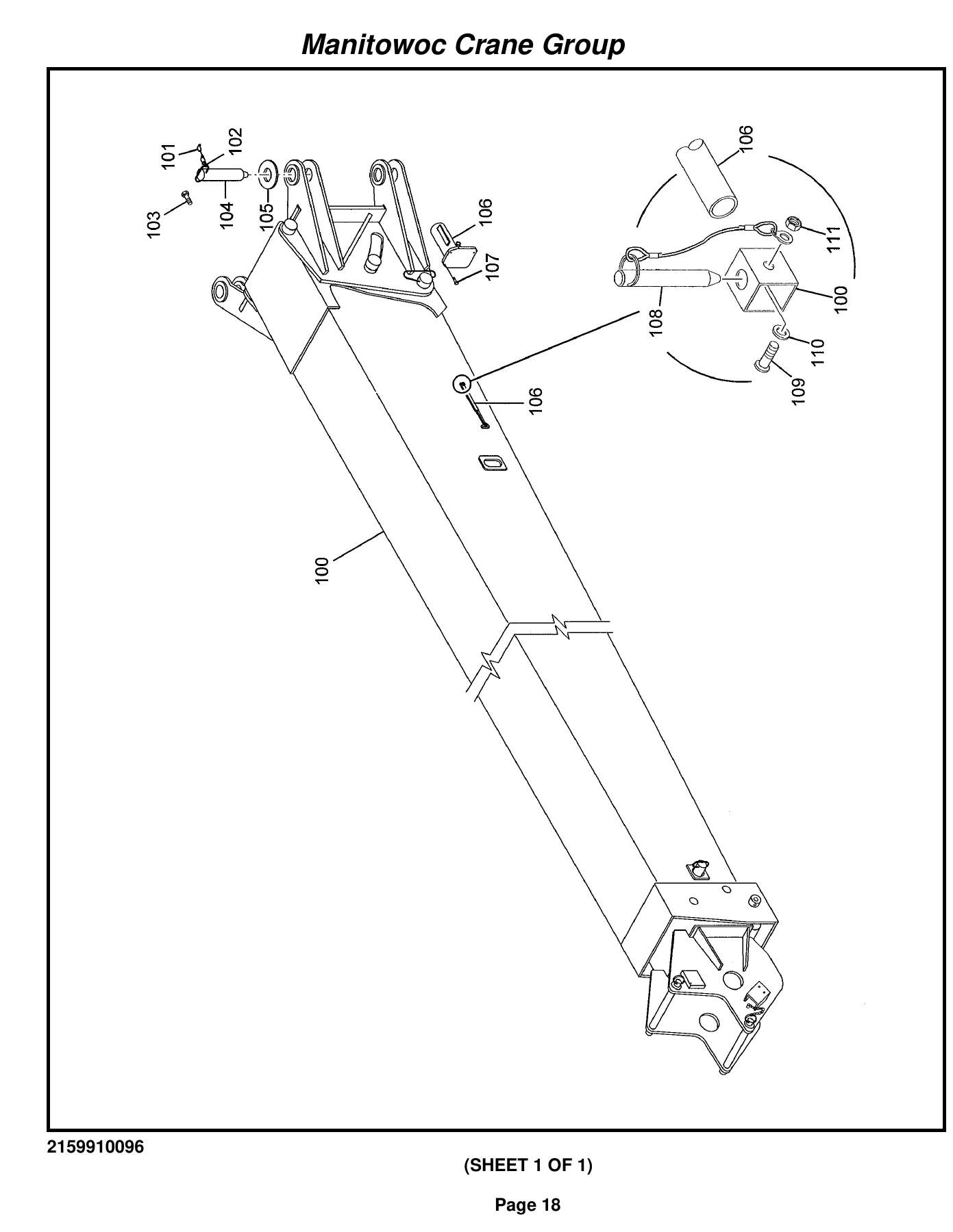
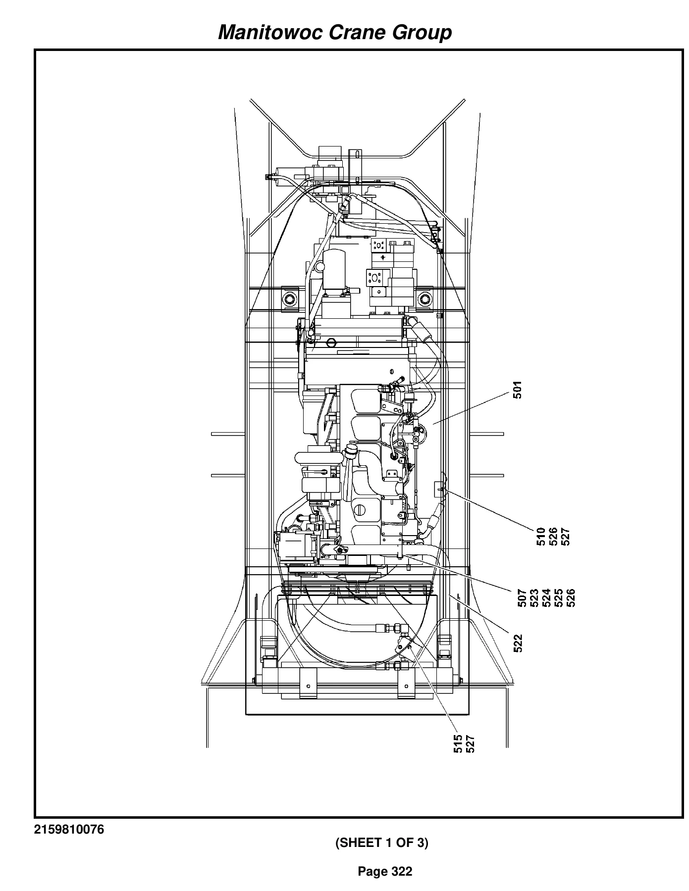
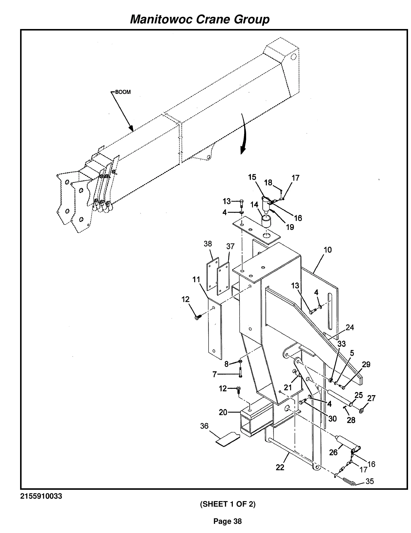
The first twelve sheets are the Machine Component Index, numbered I to XII, listing each installation and assembly by item number, part number, description and page. After that the body pages run from Page 1 to Page 659 in a repeating rhythm: a full-page line drawing showing the assembly with numbered balloons, followed by the tabulated list under the columns Item, FN, Part, Qty and Description. The drawing and the list share the balloon numbers, so you locate the component visually first and then read across to the part number and quantity.
The FN column carries the footnote codes that tell you how a part can actually be bought. An asterisk marks a repair kit or a part supplied inside one, a hash marks an item serviced as an assembly only, a plus sign points to a further breakdown within the same group, and a tilde directs transmission repair parts to an Allison dealer. Sub-lines reading INCLUDES THE FOLLOWING PARTS expand an assembly into its contents, while notes such as NOT AVAILABLE AS ASSEMBLY and NSS warn you before you order something that cannot be supplied that way. Learning these five or six markers is what turns this book from a picture catalogue into a working ordering tool.
Chapters Covered
- Boom Group – four-section boom assembly with base, inner mid, outer mid and fly and nose sections
- 6.31″ telescope cylinder assembly and counterbalance valve
- Boom pivot shaft installation
- Two-over-three sheave installation and 5/8″ rope sheave assemblies
- 26′-45′ offsettable boom extension installation and assembly, mast assembly, bottle jack rework and bottle jack cylinder
- Extension carrier installation, weight and chain assembly
- Hook block assembly and 7.5 ton overhaul ball assembly
- iFlex 5 LMI boom kit, LWG508 cable reel, junction box assemblies, A2B flag retainer and two-pin dummy plug connector
- 5/8″ wedge socket assembly and boom extension installation kit
- Boom angle indicator installation with pointer assembly
- Cab Group – cab installation and cab section
- Sliding skylight, rear window assembly, cab cable and 12 volt cab fan
- Single-axis seat installation and assembly, single-axis controller, superstructure seat harness
- RT “E” series acoustics installation and kit
- Front console installation and front console panel assembly
- Cab electrical system installation, console relay panel and its harness
- 360 degree lever installation, rear cab cover, sun screen installation
- Air conditioning and heater installation with cab heater and air conditioner kit
- iFlex 5 superstructure LMI kits and internal lightbar kit
- Brake pedal, transmission shifter and lock pin rod installations
- Steer valve installation and steering control valve assembly
- Air throttle pedal installation and treadle valve assembly
- iFlex 5 cab kit with central unit and graphic console, cab LMI kit installation
- Brake proximity switch installation and normally closed proximity switch
- Telescope pedal replacement plate installation
- Control Valve Group – superstructure control valve installation
- Directional control valve assembly with 2700 PSI, 3000 PSI, 3500 PSI and 3700 PSI relief valves
- Pressure reducing valve with solenoid and additional directional control valve
- Hydraulic master cylinder, brake booster and master cylinder assemblies
- Superstructure supply, pressure and return hydraulic lines with residual check valve
- Lift, main and auxiliary hoist, telescope, swing and swing brake, LMI and brake hydraulic line installations for both superstructure and cab
- Steer and throttle hydraulic line installations – cab
- Hoist Group – main hoist installation and hoist assembly
- Hoist rotation indicator and central processing unit control assembly
- Hoist mirror installation
- Turntable Group – Kaydon turntable bearing and drive installation with turntable section
- Swing drive motor assembly, swing lock installation and lock assembly
- Counterweight installations and bearing bolt installation
- Lift cylinder installation and cylinder assembly with holding valve
- Valve cover installation, superstructure electrical system installation and harness
- Manual turntable bearing lube installation
- Engine Group – engine hood installation
- Cummins B5.9E engine installation and engine assembly (without air conditioning)
- Transmission assembly broken out as converter housing, case and rear cover, turbine shaft, drive plate, gear and torque converter, auxiliary drive, pump drive, forward shaft, reverse shaft, reverse idler, low speed shaft, idler shaft, output shaft, disc brake, charging pump and filter, and electric control valve groups
- Transmission control valve assembly, gear pump and piggyback pump assemblies, parking brake assembly
- Engine electrical system installation, engine harness and RT530E2 engine cable kit
- Radiator installation, radiator assembly and surge tank
- Exhaust system installation, air intake installation and air cleaner assembly
- Coolant strainer installation and engine hood grill installation
- Drive Train Group – drive line installation and drive line assemblies
- Axle Group – rear axle lockout, service brake, rear steer and front steer hydraulic line installations
- Front and rear axle installations with the drive/steer axle assembly split into differential, housing, hub and shaft, and brake groups
- Disc-brake assembly, 2 1/2″ steer cylinder (also used as a cab tilt cylinder) and 5″ lockout cylinder
- 20.5 X 25 tire and wheel installation and assembly
- Outrigger Group – outrigger float installation, float assembly and outrigger hydraulic lines
- Frame Group – carrier frame complete and carrier frame assembly
- Outrigger beam installation and assembly, 4″ outrigger jack cylinder, 2 1/2″ outrigger extend cylinder
- RT500E2 standard decal installations, RT530E nomenclature decals and decal hardware kit
- Fender installation, exterior lights installation, turn signal and stop light assemblies
- Hook block tie down, battery box cover, rear view mirror and step extension installations
- Carrier electrical system installation, carrier harness and engine coolant level harness
- Hydraulic tank installation with tank and return filter assembly
- Outrigger control manifold, outrigger and rear steer selector valve, double solenoid valve, four wheel drive solenoid valve, normally closed pressure switch and 4-way solenoid valve
- Supply, pressure and return hydraulic line installation with high speed boost valve
- Fuel tank installation and fuel tank assembly
- Battery installation and RT530E2 battery cable kit
- Throttle diagnostics installation, engine relay panel and harness, RT500E relay panel cable kit, diagnostics box, engine service box harness, throttle control assembly and throttle cylinder
- Schematic – electrical schematic RT500E2 and hydraulic schematic RT530E2 identified in the component index
Taken as a whole, the book gives a technician a single trustworthy route from a broken component on the machine to a part number that can be ordered. Whether the job starts at the boom nose, inside the cab console, at the swing bearing, under the engine hood or out at an outrigger box, the same path applies: find the group, read the drawing, take the balloon number, check the footnote, note the quantity. That consistency is what makes the 2005 Grove RT530E 30-ton crane parts manual usable by a fitter who has never worked on an RT500E series carrier before.
Machine Hardware the Listings Reach
Power and driveline coverage runs from the Cummins B5.9E engine installation through the radiator, surge tank, exhaust, air intake and coolant strainer, then into the transmission, which is broken down far enough to identify individual shafts, idlers, the torque converter, the disc brake pack, the charging pump and filter and the electric control valve. Drive lines carry on to front and rear drive/steer axles that are each decomposed into differential, housing, hub and shaft and brake sub-groups, ending at the 20.5 X 25 tires and wheels.
On the hydraulic side the listings cover the superstructure directional control valve with its stack of relief cartridges, the pressure reducing valves, the outrigger control manifold, the selector and solenoid valves on the carrier, the high speed boost valve, the return filter in the hydraulic tank and every numbered line installation feeding lift, telescope, swing, hoist, steer, brake, outrigger and axle lockout circuits. Actuators are listed individually, including the 6.31″ telescope cylinder, the lift cylinder with its holding valve, the 4″ outrigger jack cylinders, the 2 1/2″ outrigger extend and steer cylinders and the 5″ lockout cylinder. Electrically, the manual maps the superstructure, cab, engine and carrier harnesses, the console and engine relay panels with their fuse and relay ratings, the gauges and indicator lamps, the diagnostics box and the iFlex 5 load moment indicator from cable reel to graphic console.
IMAGES PREVIEW
Appendices and Lookup Tools
- Appendix A – Alphabetical Index: roughly fifty-eight pages running from a component description to its part number and page, for when you know what the part is called but not what it is numbered.
- Appendix B – Numerical Index: around seventy pages working the other way, from a number stamped on a part to its description and the pages it appears on.
- Appendix C – Recommended Spare Parts List: roughly eighteen pages of suggested stocking quantities set out against 1 Yr, 2 Yr and 3 Yr columns.
- Appendix D – Belt and Filter Maintenance List: consumables against 1000 Hrs and 2000 Hrs columns, covering the drive belt, oil and fuel filters, air cleaner element, transmission filter, fuel/water separator, breathers and hydraulic return element.
- Appendix E – Foot Note Index: the full legend for every FN symbol used in the parts tables.
Planning Maintenance and Stock
The two planning appendices are what lift this beyond a one-off repair reference. Appendix D turns a service interval into a shopping list, so a 1000 hour or 2000 hour service can be kitted before the crane comes off hire rather than after. Appendix C does the same for a fleet or workshop store, suggesting how deep to stock seal kits, cylinder repair kits, switches, relays, sheave bearings and universal joints across a one, two or three year horizon. Read alongside the exploded views, they make it straightforward to decide when a seal kit will do and when a complete cylinder or valve assembly is the sensible order.
Order Your Copy and Download It Now
With the 2005 Grove RT530E 30-ton crane parts manual on hand you can strip and rebuild a telescope or lift cylinder with the correct seal kit, replace boom wear pads and shims in the right quantities, chase a dead circuit through the named harness and relay panel, rebuild an axle hub or brake group, service the swing drive and turntable bearing, renew outrigger jack and extend cylinders, and quote a repair accurately because every part number and quantity is printed beside the drawing it belongs to. Ordering from a manual tied to serial number 224288 also removes the most expensive mistake in crane parts work: buying a component that fits a different build of the same model.
Delivery is immediate. Complete checkout and the PDF is available to download straight away, with no shipping charge and no waiting for a printed book. Save it to a laptop, tablet or phone, keep a copy on the workshop network, and print just the pages the current job needs.
Reviews
There are no reviews yet.