
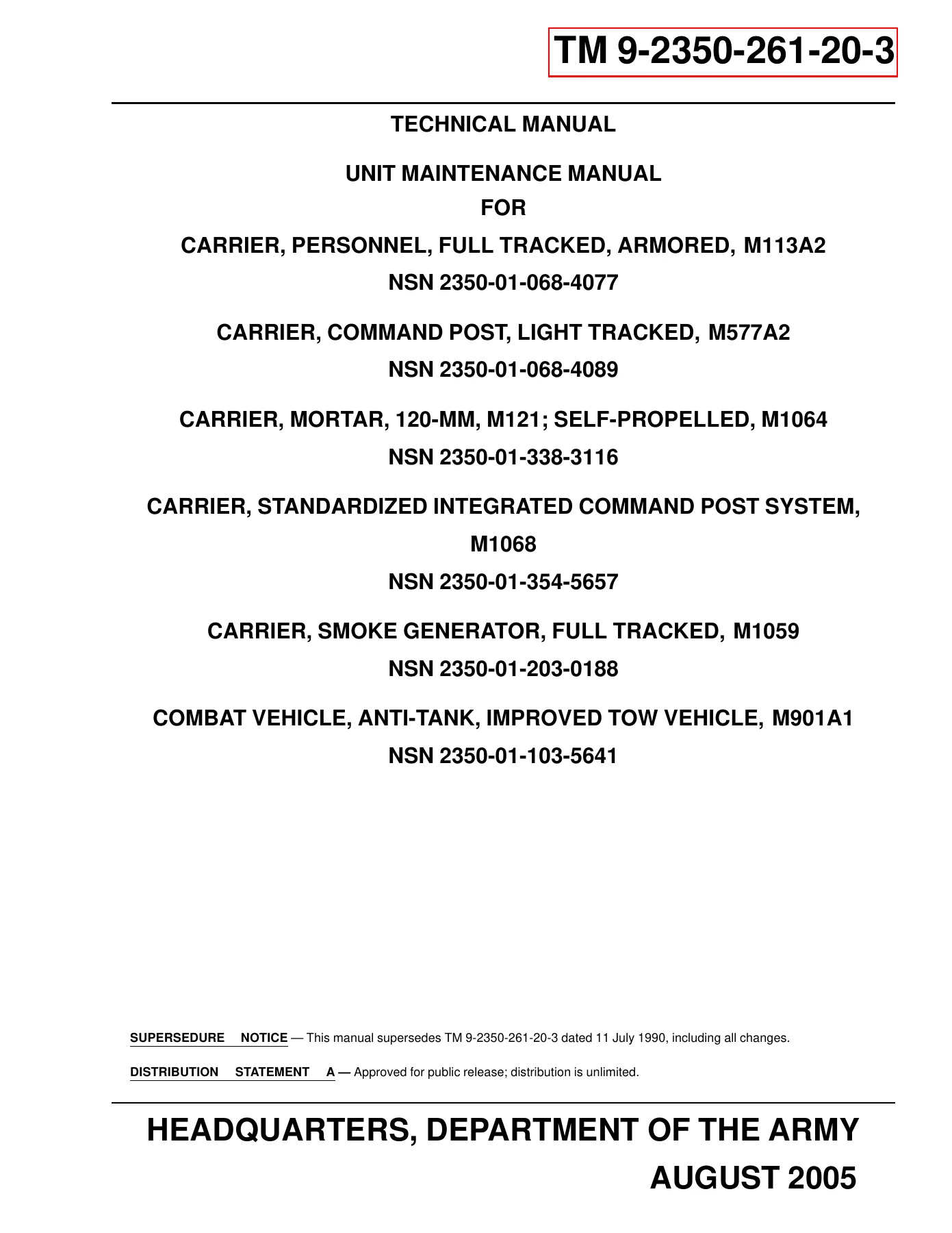
2005 M113A2 M577A2 M1064 M1068 M1059 M901A1 Unit Maintenance Manual TM 9-2350-261-20-3 Volume 3
Original price was: $44.95.$26.95Current price is: $26.95.
Volume 3 of TM 9-2350-261-20-3 provides unit maintenance procedures for the M113A2, M577A2, M1064, M1068, M1059, and M901A1 carrier family. Its 937 pages cover hull components, hatches and cupolas, ramp controls, hydraulic ramp and suspension lockout equipment, auxiliary generator fuel components, personnel heater components, and related inspection, removal, installation, repair, adjustment, and service tasks.
Description
2005 M113A2 M577A2 M1064 M1068 M1059 M901A1 Unit Maintenance Manual TM 9-2350-261-20-3 Volume 3
The 2005 M113A2 M577A2 M1064 M1068 M1059 M901A1 Unit Maintenance Manual TM 9-2350-261-20-3 Volume 3 is a detailed unit-level maintenance reference for six tracked carrier configurations identified on the manual cover. Volume 3 concentrates on hull maintenance, access panels and floor plates, driver and commander hatch hardware, cargo and mortar hatch systems, ramp controls, hull welding guidance, smoke grenade launcher components, the ramp and suspension lockout hydraulic system, auxiliary generator fuel components, and personnel heater equipment. The procedures are organized as numbered work packages, allowing a mechanic to move directly to the component or task being serviced.
File Details
- Manual type: Unit Maintenance Manual
- Document number: TM 9-2350-261-20-3
- Volume: 3
- Models covered: M113A2, M577A2, M1064, M1068, M1059, M901A1
- M1064 identification on cover: Carrier, Mortar, 120-MM, M121; Self-Propelled, M1064
- Language: English
- Page count: 937 pages
- File format: PDF
- Issue date: 26 August 2005
- Revision: Original 0
- Issuing authority: Headquarters, Department of the Army
Built Around Unit Maintenance Work Packages
This volume is arranged for hands-on maintenance rather than general operating instruction. Individual work packages identify the maintenance level and commonly specify required tools, materials or parts, personnel, and the equipment condition that should exist before work begins. Depending on the job, the procedure then walks through removal, disassembly, cleaning, inspection, repair or replacement, assembly, installation, adjustment, service, and follow-through checks. Safety warnings and cautions are positioned with the applicable task, while many procedures provide exact tightening torques, clearances, or adjustment dimensions where the work requires them.
The manual also distinguishes between carrier configurations inside the procedures. Examples include model-specific power plant rear access panels, floor plates, hatch systems, seating, stowage equipment, generator or auxiliary power equipment, armor and launcher supports, mortar hatch hardware, and heater plumbing. That model-specific organization is valuable when several M113-family configurations are maintained in the same shop because it helps the technician follow the steps written for the actual carrier rather than treating all variants as identical.
Chapters Covered
- Chapter 24 – Unit Maintenance Instructions for Hull Maintenance
- Lifting eyes, rear tiedown plates, towing hook and eye pads, towing pintle, and tow cable pad
- Trim vane replacement and repair, control linkage, release, and release adjustment
- Power plant door combat lock, power plant door replacement and repair, and hull front access cover
- Driver’s power plant access panel and model-specific power plant rear access panels
- Power plant bottom access cover, final drive drain plugs, and hull poppet valves
- Rear, compartment, and model-specific floor plate replacement
- Driver’s compartment hull access covers and power plant grill support arm
- Driver’s hatch cushioning pad, vision block locks and seals, interior lock and latch, periscope guard, cover, latch, and bumper
- M901A1 driver hatch repair including inspection, repair, assembly, installation, and adjustment
- Commander’s cupola and hatch components including pads, vision blocks, brake assembly, azimuth lock, interior latch, covers, hold-open hardware, and machine gun mount components
- Cargo hatch latch, door, hold-open hook and bumpers, plus M901A1 cargo hatch latch and support
- M1064 mortar hatch interior release mechanisms, exterior catches and bumpers, and hatch covers
- Rear compartment air ventilator
- M577A2 4.2 kW generator set enclosure and M577A2/M1068 5.0 kW auxiliary power unit reference
- M901A1 side armor, low-stow cushion base, high-stow launcher support, and high-stow bracket
- Driver, commander, operator, radio operator, crew, and personnel seating and platforms by configuration
- Tables, shelves, tent mounts, ammunition racks, radio racks, map board and storage, missile and launcher stowage, cable and antenna brackets
- Dataplates, stencils, decals, markers, cushioning pads, and equipment stowage hardware
- Chapter 25 – Unit Maintenance Instructions for Ramp Controls, Ramp, and Ramp Door
- Ramp lock adjustment for different carrier configurations
- Ramp lock handles, levers, cables, and linkage replacement
- Wire rope and pulley replacement
- Ramp door seal, hook and spring, handles and shaft, and ramp seal replacement
- Ramp vision port and shield repair or replacement where applicable
- Ramp bracket, ramp door stop bracket, and drain plug replacement
- Chapter 26 – Unit Maintenance Instructions for Welding – Cautions and Instructions
- Hull repair by welding
- Chapter 27 – Unit Maintenance Instructions for Smoke Grenade Launcher
- Smoke grenade launcher guard, plate, and base replacement
- Smoke grenade launcher wiring harness replacement
- Chapter 28 – Unit Maintenance Instructions for Hydraulic System – Ramp and Suspension Lockout
- Hydraulic fluid flow diagram for the M113 family of vehicles
- Procedure to raise or lower an inoperable or unsafe ramp
- Ramp pump-to-tank strainer tube and pressure relief valve hose replacement
- Relief valve, quick-disconnect, control valve, and hydraulic tank hose or tube replacement
- Hydraulic tank strainer replacement, hydraulic tank repair or replacement, and hydraulic tank service
- Ramp pump and ramp control valve replacement
- Ramp cylinder hose, breather hose, and ramp cylinder replacement
- Chapter 29 – Unit Maintenance Instructions for Auxiliary Generator
- 5.0 kW auxiliary power unit fuel shutoff valve replacement for M577A2 and M1068
- 5.0 kW auxiliary power unit valve-to-bulkhead and bulkhead-to-hull fuel supply hose replacement
- Chapter 30 – Unit Maintenance Instructions for Personnel Heater Kit Component
- Personnel heater fuel pump and fuel filter service
- Bleeding air from compartment heater fuel lines
- Model-specific personnel heater fuel pump replacement
- Fuel tank, bulkhead, pump, filter, heater, and shutoff-valve hose and fitting replacement
- Personnel heater control box replacement and repair
- Personnel heater fuel filter and bracket replacement
- Personnel heater duct replacement and repair
- Personnel heater assembly replacement and repair
- Heater air intake and exhaust pipe replacement
Taken as a whole, TM 9-2350-261-20-3 Volume 3 gives a unit mechanic a structured set of component-level maintenance instructions for body, access, hatch, ramp, hydraulic, auxiliary power, and heating systems across the listed carrier variants. The combination of illustrated removal and installation steps, exploded assemblies, configuration notes, warnings, torque instructions, and adjustment criteria makes the volume especially useful when work extends beyond routine checks and requires parts to be removed, inspected, repaired, adjusted, or reinstalled correctly.
IMAGES PREVIEW
Illustrated Procedures and Configuration-Specific Detail
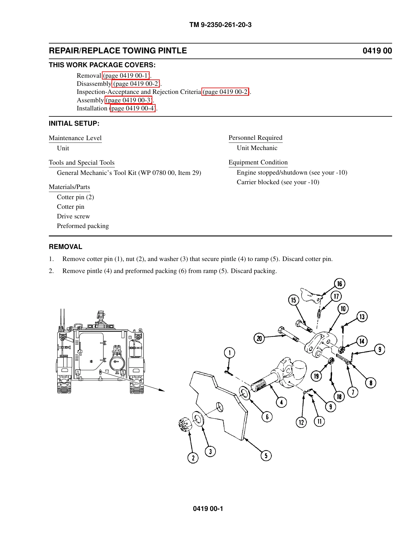
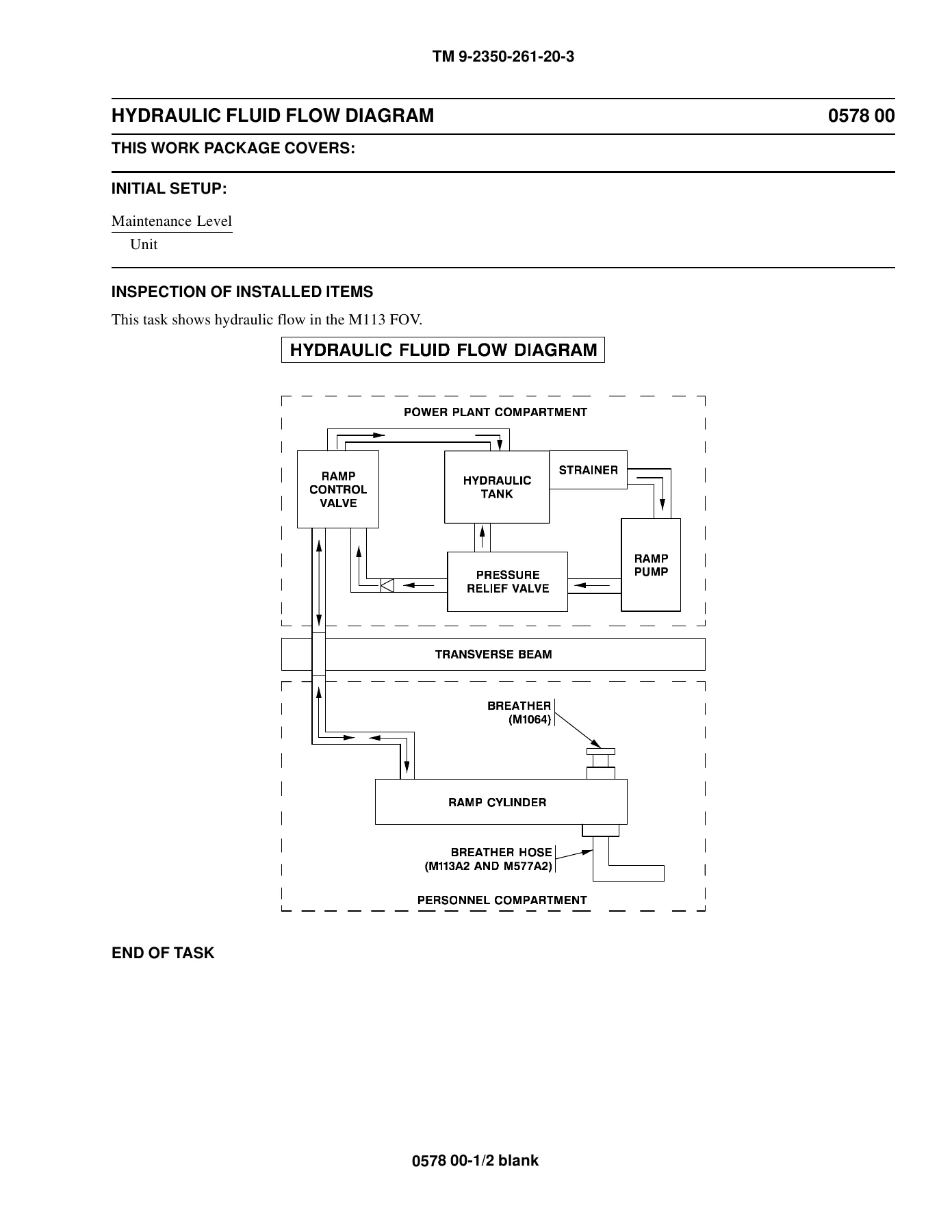
Many work packages pair the written steps with line drawings that show component locations, attachment hardware, assemblies, and installation relationships. For example, the towing pintle procedure includes removal, disassembly, inspection, assembly, and installation views; hatch and cupola procedures illustrate locks, springs, seals, latches, supports, and mounting hardware; and the hydraulic chapter includes a fluid-flow diagram identifying the ramp control valve, hydraulic tank, strainer, pressure relief valve, ramp pump, ramp cylinder, and model-specific breather arrangement. These illustrations help connect the numbered procedure steps to the physical parts being handled.
Adjustment data is included where the task depends on correct fit or engagement. Examples in this volume include hatch latch clearances, bumper compression, launcher bracket clearances, ramp and hatch engagement dimensions, and numerous specified tightening torques. The manual also calls out conditions that differ by model, early or late configuration, or installed equipment, so the reader can follow the branch that matches the carrier being maintained.
Put the Correct Procedure at the Work Area
The 2005 M113A2 M577A2 M1064 M1068 M1059 M901A1 Unit Maintenance Manual TM 9-2350-261-20-3 Volume 3 supports real unit-maintenance jobs such as removing and installing hull hardware, repairing hatch and cupola assemblies, adjusting ramp mechanisms, servicing hydraulic components, replacing heater fuel and air-system parts, and completing model-specific body or stowage work. Using the documented sequence, safety information, inspection points, torque values, and adjustment measurements helps reduce guesswork when parts must go back together in the correct position and condition. This is an instant PDF download with no shipping delay, so you can keep it on a phone, tablet, laptop, or desktop computer and print the pages needed for the job.
Reviews
There are no reviews yet.