
2006 Audi A8 Quattro 4.2L V8 BFM BGK Engine Mechanical Repair Manual
Original price was: $29.95.$18.95Current price is: $18.95.
354-page engine mechanical repair manual for the 2006 Audi A8 Quattro 4.2L V8 5V, engine codes BFM and BGK. Covers engine removal and installation, toothed belt timing, crankshaft, pistons and connecting rods, cylinder heads, valvetrain, lubrication, cooling, exhaust and secondary air injection, with torque specifications and special tool references throughout.
Description
The 2006 Audi A8 Quattro 4.2L V8 BFM BGK Engine Mechanical Repair Manual
The full engine mechanical service documentation for the 4.2 liter V8 5-valve engine used in the Audi A8, covering engine codes BFM and BGK. Every procedure in this 354-page workshop document is written around the engine as it actually sits in the car – from activating vehicle jack mode and hoisting the body, to lowering the engine and transmission out with the subframe, to rebuilding the crankshaft, pistons and cylinder heads on the bench and timing the toothed belt again on refit.
File Details
- Manual type: Engine mechanical repair manual (service and repair documentation)
- Brand: Audi
- Model: A8 Quattro
- Model year covered: 2006
- Engine: 4.2 Liter V8 5V, engine codes BFM and BGK
- Language: English
- Page count: 354 pages
- File format: PDF
Chapters Covered
- 00 – General, Technical Data
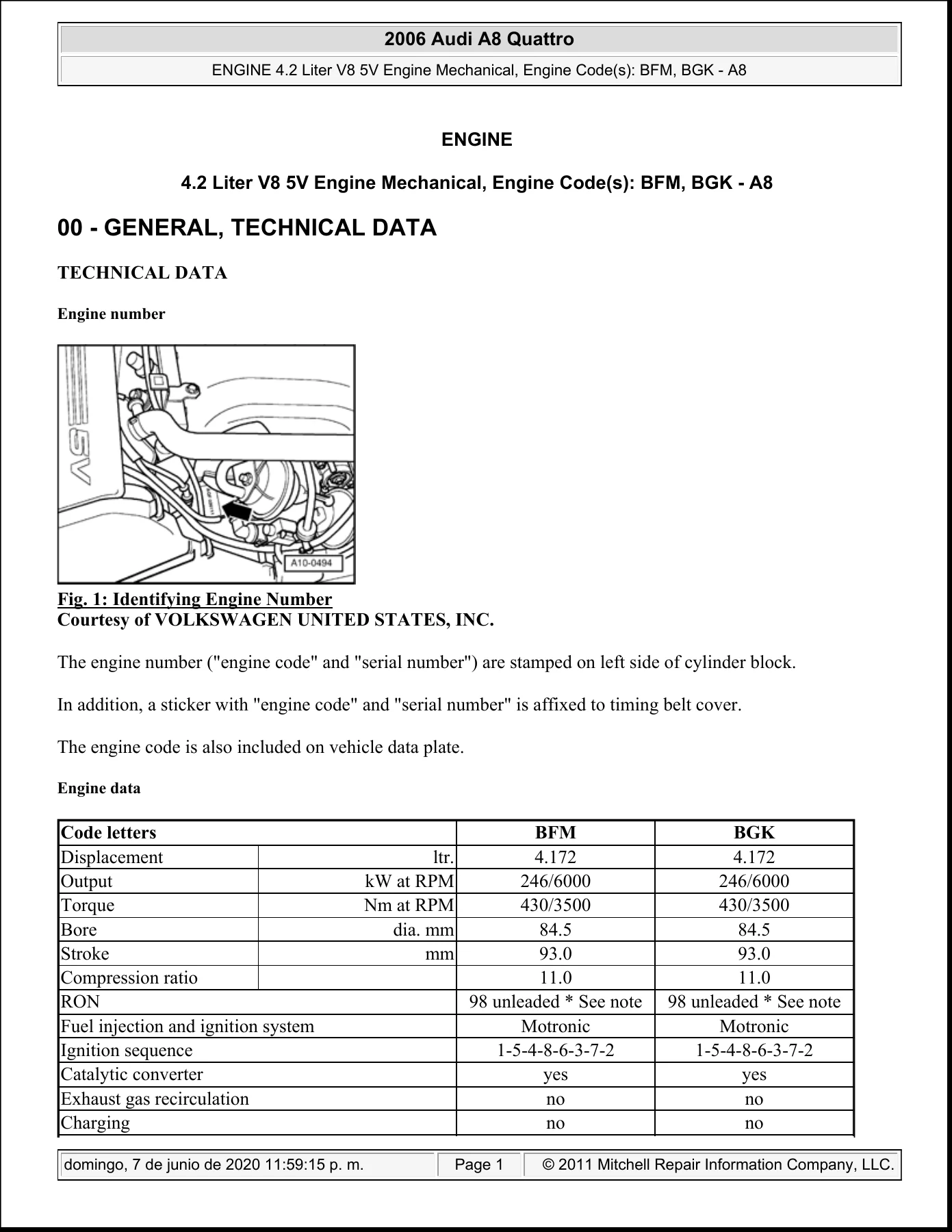
- Engine number location and identification
- Engine data table for BFM and BGK
- 10 – Engine – Assembly
- Engine, removing and installing
- Engine mount, removing and installing (left and right)
- Torque support with torque support valve N382, assembly overview
- 13 – Engine – Crankshaft, Cylinder Block
- Lock carrier, pulling toward front
- Ribbed belt drive, assembly overview, removal and installation
- Ribbed belt alignment, checking
- Vibration damper, removing and installing
- Toothed belt guards and toothed belt drive, assembly overview
- Toothed belt, removing, installing and timing adjustment
- Sealing flange and drive plate, assembly overview
- Crankshaft seal (ribbed belt side), front and rear sealing flange
- Drive plate, removing and installing
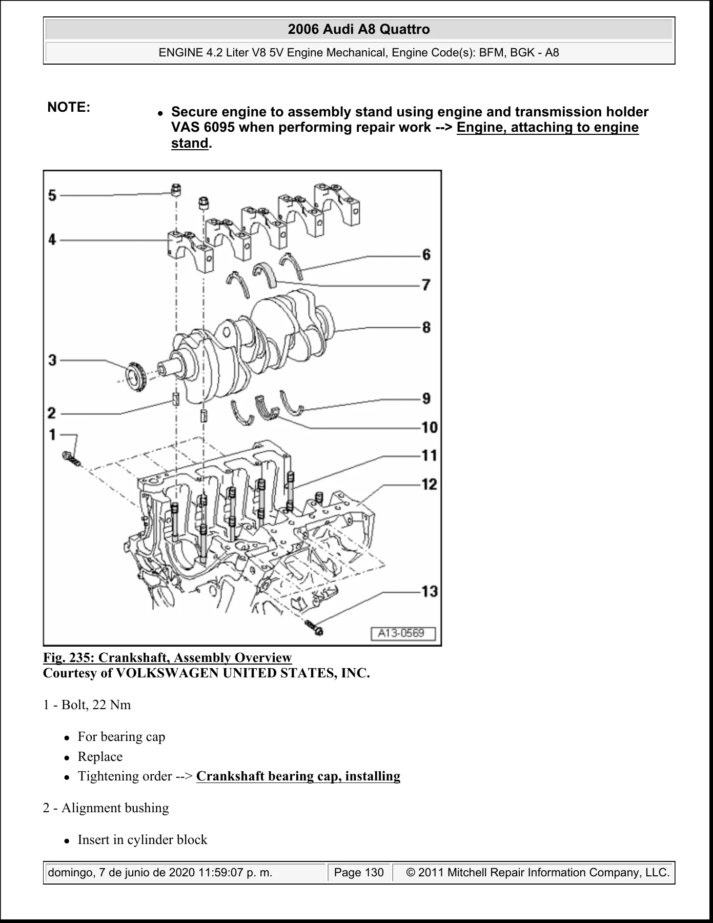
- Crankshaft, assembly overview, bearing cap identification and installation
- Allocation of crankshaft bearing shells
- Crankshaft dimensions, axial clearance and radial clearance measurement
- Oil pump drive sprocket, removing and installing
- Pistons and connecting rods, assembly overview
- Piston ring gap and ring-to-groove clearance checks
- Checking pistons and cylinder bores
- Installed position of piston and piston/cylinder allocation
- Radial clearance of connecting rod, checking
- 15 – Engine – Cylinder Head, Valvetrain
- Cylinder head, assembly overview and distortion check
- Left and right cylinder head cover, removing and installing
- Left and right cylinder head, removing
- Cylinder head, installing and tightening sequence
- Compression pressures, checking
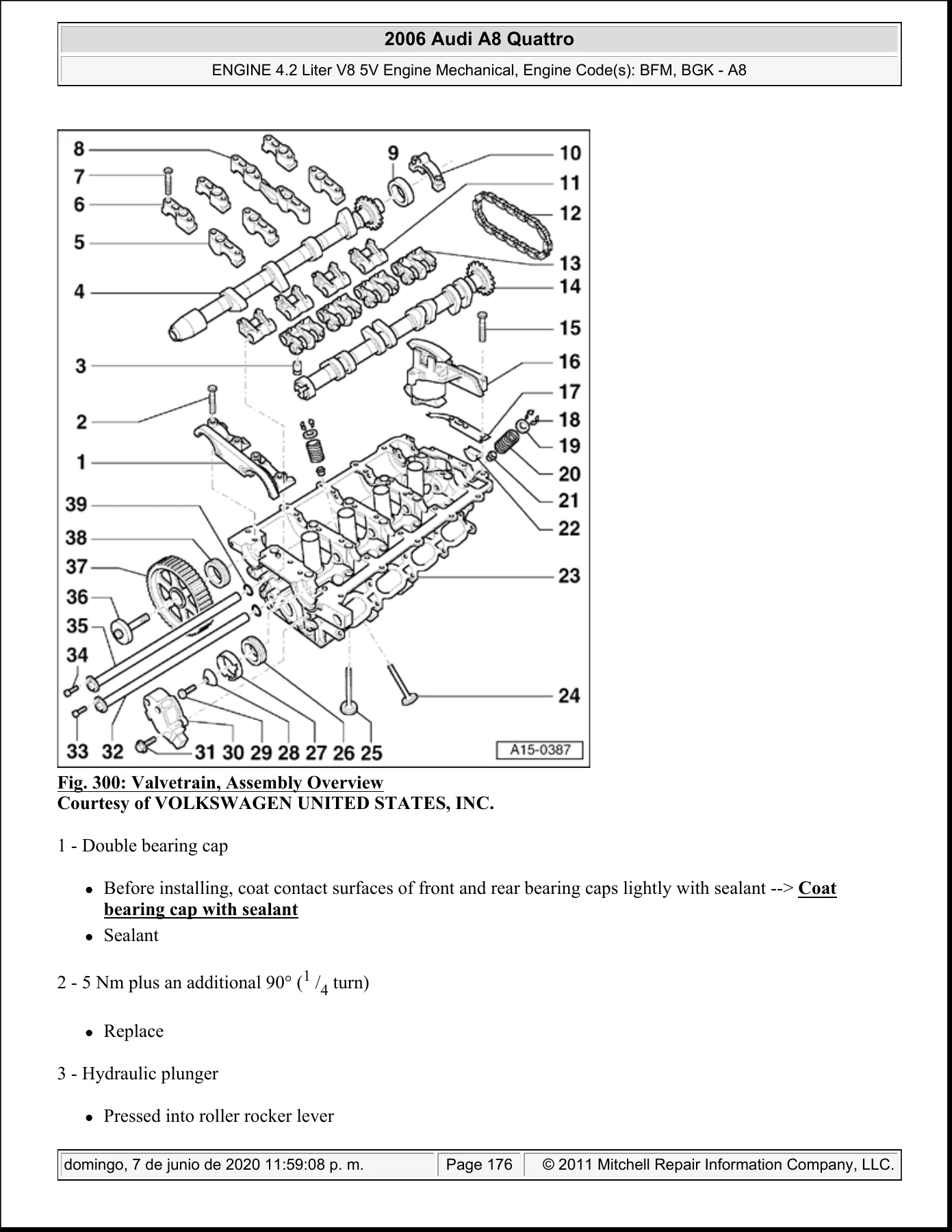
- Valvetrain, assembly overview and valve dimensions
- Camshaft axial clearance, camshaft seals and CMP sensor seals
- Camshafts and camshaft adjusters, left and right cylinder head
- Roller rocker lever, removing and installing
- Valve stem seals, replacing
- Valve guides, checking and valve seats, reworking
- Camshaft adjustment, checking with diagnostic tester
- 17 – Engine – Lubrication
- Lubrication system components and oil pump, assembly overview
- Oil Level Thermal Sensor G266, removing and installing
- Lower and upper oil pan, removing and installing
- Chain drive for oil pump and oil pump, removing and installing
- Oil check valves, replacing
- Oil pressure and oil pressure switch F1, checking
- Oil level, checking and oil filter housing, removing and installing
- 19 – Engine – Cooling System
- Cooling system components, removing and installing
- Connection diagrams for coolant hoses, with and without auxiliary heater
- Cooling system, draining and filling
- Cooling system, checking for leaks and pressure relief valve in cap
- Coolant pump and coolant thermostat, removing and installing and checking
- Coolant pipe to oil filter housing, oil cooler, radiator and coolant fans
- Converting to radiator with bypass
- 26 – Exhaust System, Emission Controls
- Exhaust system, assembly overview (front and rear)
- Individual suspension components and center bracket
- Installation position of front and rear double clamps
- End pipe, replacing and separating points
- Left and right exhaust manifold, removing and installing
- Catalytic converter with left and right front muffler
- Left and right front muffler, removing and installing
- Exhaust system, installing free of tension and checking for leaks
- Tail pipes, aligning
- Secondary Air Injection (AIR) system, function and component overview
- Combination valves, checking for function and leaks
- Secondary Air Injection Pump Motor V101 and combination valves, removing and installing
Read as a whole, this is a single-system service document rather than a general owner’s handbook. It assumes the technician already has the car on a lift and is working on the engine itself, so the content stays concentrated on mechanical procedures, fits and measurements: which bolts come out in which sequence, which fasteners are single-use, where alignment bushings and dowel sleeves must be seated, how the engine carrier, subframe and torque support interact, and what the correct clearance or pressure value is once a component is back together. The torque specification tables and the special tool call-outs appear next to the job they belong to, which means the removal, inspection and refit steps for a given component stay on the same run of pages instead of being split across separate chapters.
Engine Removal and the Subframe Route
The removal procedure in this manual is not a top-side lift-out. It documents taking the engine down with the transmission and subframe attached, using a scissor lift table, with the body raised and the front end pulled apart first. That means the sequence covers the plenum chamber covers, wiper arms, wind deflector, dust and pollen filter, battery disconnection with the Telematic service mode caution, noise insulation, wheel housing liners, front bumper and lock carrier, coolant draining from the oil filter bracket and the engine, fuel supply and return lines, oxygen sensor and solenoid valve connectors, power steering lines, A/C compressor hung to one side with its lines still connected, and the dome brace. The manual then walks through supporting the wheel bearing housings, separating the drive axles, stabilizer, guide control link and control link, the drive shaft heat shield, selector lever cable, and finally the subframe and engine carrier bolts – marked against the long member before loosening and removed in diagonal stages.
IMAGES PREVIEW
Toothed Belt Timing and Camshaft Work
Valve timing on the 4.2 V8 is covered in unusual detail, including the TDC cylinder 5 reference, the camshaft holder and locking pin tools, the crankshaft holder fitted into the oil pan bore, the eccentric pulley pretension procedure, the 5 mm hex socket wrench inserted between the tensioning lever and piston, and the final tensioner dimension check. Camshaft removal and installation is documented separately for the left and right cylinder heads because the drive chain routing differs between banks – the left bank uses a 15-roller span between the markings, the right bank 16 rollers – and the manual flags that difference explicitly so the chain is not assembled with the wrong count.
Specifications You Can Work From
Engine data is given for both codes: 4.172 liter displacement, 84.5 mm bore, 93.0 mm stroke, 11.0 compression ratio, 246 kW at 6000 RPM, 430 Nm at 3500 RPM, Motronic injection and ignition, and the 1-5-4-8-6-3-7-2 firing order. Valve timing at 1 mm lift is listed for intake and exhaust, and the engine number location is identified on the left side of the cylinder block with a matching sticker on the timing belt cover and on the vehicle data plate. Repair-level values include cylinder head tightening in four stages, crankshaft toothed belt sprocket torque, connecting rod radial clearance, crankshaft axial clearance, compression pressure with a wear limit, oil pressure at idle and at 2000 RPM, thermostat opening values and coolant mixture ratios for frost protection.
Who This Manual Is For
This is bench-and-bay material for a technician, a workshop, or a technically confident owner running a timing belt job, a head gasket replacement, a camshaft adjuster repair or a full engine-out reseal on a 2006 A8 Quattro with the BFM or BGK 4.2 V8. It is equally usable for someone rebuilding a removed engine on a stand, since the crankshaft, piston, connecting rod, valvetrain and lubrication chapters stand on their own once the engine is out.
Get the Job Done Right
With this 2006 Audi A8 Quattro 4.2L V8 BFM BGK Engine Mechanical Repair Manual you can pull the engine and transmission cleanly, split them safely, time the toothed belt correctly on the first attempt, replace cylinder heads and head gaskets to the specified tightening stages, rebuild the bottom end to measured clearances, and diagnose oil pressure and secondary air injection faults against real values instead of guesswork. Those numbers matter on a V8 with this compression ratio and this valve arrangement – an incorrect belt tension, a mis-set camshaft or a reused single-use fastener is an expensive mistake. The file is delivered instantly as a PDF after purchase, with no shipping and no waiting, and it opens on a laptop, tablet or phone in the workshop and prints page by page when you want the procedure on paper next to the car.
Reviews
There are no reviews yet.