
2006 Sprinter Transmission Service Repair Manual
Original price was: $19.95.$12.95Current price is: $12.95.
Description
📘 DOCUMENT OVERVIEW
This comprehensive digital service manual provides detailed diagnostic information and repair procedures for the NAG1 Electronic Automatic Transmission and Shift Lever Assembly found in Mercedes-Benz Sprinter vans (VA model). It’s an invaluable resource for professional mechanics and experienced DIY enthusiasts tackling complex transmission issues.
🔧 Key Features & Content:
- System Identification: Learn how to quickly identify the NAG1 transmission system in your Sprinter van.
- Functional Operation: Gain a deep understanding of the NAG1 transmission’s operation, including controller modes, solenoid functions, and shift scheduling.
- Diagnostic Trouble Codes (DTCs): The manual thoroughly explains how to interpret and troubleshoot DTCs, differentiating between active and stored codes. A detailed table lists numerous DTCs with page references for specific diagnostic procedures.
- Six-Step Troubleshooting: A clear, six-step troubleshooting process guides you through the diagnostic process, ensuring efficiency and accuracy.
- Diagnostic Procedures: The heart of this manual is its extensive section on diagnostic procedures. It addresses a wide array of transmission symptoms with step-by-step instructions, diagrams, and troubleshooting trees. These procedures cover communication issues, solenoid problems, sensor faults, and more.
- Component Descriptions: Detailed descriptions of key transmission components, including the shift assembly, solenoids, sensors, and control modules, are provided with clear diagrams.
- Safety Precautions: The manual emphasizes technician safety with detailed warnings regarding carbon monoxide, high-pressure hydraulic systems, and electrical hazards.
- Tools and Equipment: A list of required tools and equipment for diagnosis and repair is provided.
- Schematic Diagrams: The manual includes clear schematic diagrams that visually represent the electrical system’s components and their interconnections. This enhances your ability to follow the diagnostic procedures effectively.
- Component Locations: Visual aids show the locations of key components, such as the engine control module, transmission control module, and solenoid assembly.
- Verification Tests: Post-repair verification test procedures ensure proper operation.
🚜 Equipment Covered: Mercedes-Benz Sprinter vans (VA model) equipped with the NAG1 automatic transmission.
⚠️ Important Notes: The manual assumes a working knowledge of automotive diagnostics and repair. While comprehensive, it requires a certain technical understanding to effectively utilize.
❌ WHAT’S NOT INCLUDED
- Step-by-step repair instructions for every component.
- Detailed parts diagrams or exploded views.
📊 RECOMMENDATION SUMMARY
| Criteria | Verdict |
|---|---|
| Technical Depth | ⭐⭐⭐⭐⭐ (comprehensive manual) |
| Ease of Use | ⭐⭐⭐⭐☆ (technical level) |
| Model Coverage | ⭐⭐⭐⭐⭐ (specific models covered) |
| Value for Technicians | ⭐⭐⭐⭐⭐ (essential resource) |
| Ideal User | Professional mechanics and experienced DIY users |
❓ FREQUENTLY ASKED QUESTIONS
💬 Customer FAQs:
Q: What models does this manual cover?
A: This manual specifically covers Mercedes-Benz Sprinter vans (VA model) equipped with the NAG1 automatic transmission.
Q: What type of procedures are included?
A: This manual includes detailed diagnostic procedures for various transmission problems, including communication issues, solenoid malfunctions, sensor errors, and more. It provides step-by-step instructions, diagrams, and troubleshooting trees for each.
Q: Is this suitable for DIY mechanics?
A: While comprehensive, this manual is best suited for experienced DIY mechanics with a strong understanding of automotive diagnostics and repair. The technical level is professional/intermediate.
Q: What format is this manual in?
A: This manual is in digital PDF format, downloadable immediately after purchase.
Q: Are there any diagrams or illustrations?
A: Yes, the manual includes numerous clear diagrams, schematics, and illustrations to aid in understanding and performing the diagnostic and repair procedures.
Q: Does it cover safety precautions?
A: Yes, the manual emphasizes technician safety with warnings about carbon monoxide, high-pressure hydraulic systems, and electrical hazards.
Q: What if I have more questions after purchasing?
A: We provide detailed contact information for follow-up questions and concerns.
📂 PDF SNAPSHOT & USABILITY REPORT
- Overall Quality: High-quality, comprehensive content.
- Content Type: Service Manual
- Language: English
- Technical Level: Professional/Intermediate
- Recommended For: Professional mechanics and experienced DIY users familiar with automotive diagnostics.
- Page Count: Approximately 144 pages
- Image Quality: Good quality diagrams and illustrations, mostly clear and easy to follow.
📋 Original Product Description:
2006 Sprinter Transmission Service Repair Manual
sample page
1.0 INTRODUCTION
The procedures contained in this manual include
all of the specifications, instructions, and graphics
needed to diagnose NAG1 Electronic Automatic
Transmission and Shift Lever Assembly problems.
The diagnostics in this manual are based on the
failure condition or symptom being present at the
time of diagnosis.
When repairs are required, refer to the appropriate
volume of the service information for the proper
removal and repair procedure.
READ THIS MANUAL BEFORE TRYING TO
DIAGNOSE A VEHICLE TROUBLE CODE.
Diagnostic procedures change every year. New
diagnostic systems may be added and/or carryover
systems may be enhanced. It is recommended that
you review the entire manual to become familiar
with all new and changed diagnostic procedures.
1.1 SYSTEM COVERAGE
This diagnostic procedures manual covers all
Sprinter (VA) equipped with a NAG1 Automatic
Transmission.
1.2 SIX -STEP TROUBLESHOOTING
PROCEDURE
Diagnosis of the NAG1 electronic transmission is
done in six basic steps:
Verification of complaint
Verification of any related symptoms
Symptom analysis
Problem isolation
Repair of isolated problem
Verification of proper operation
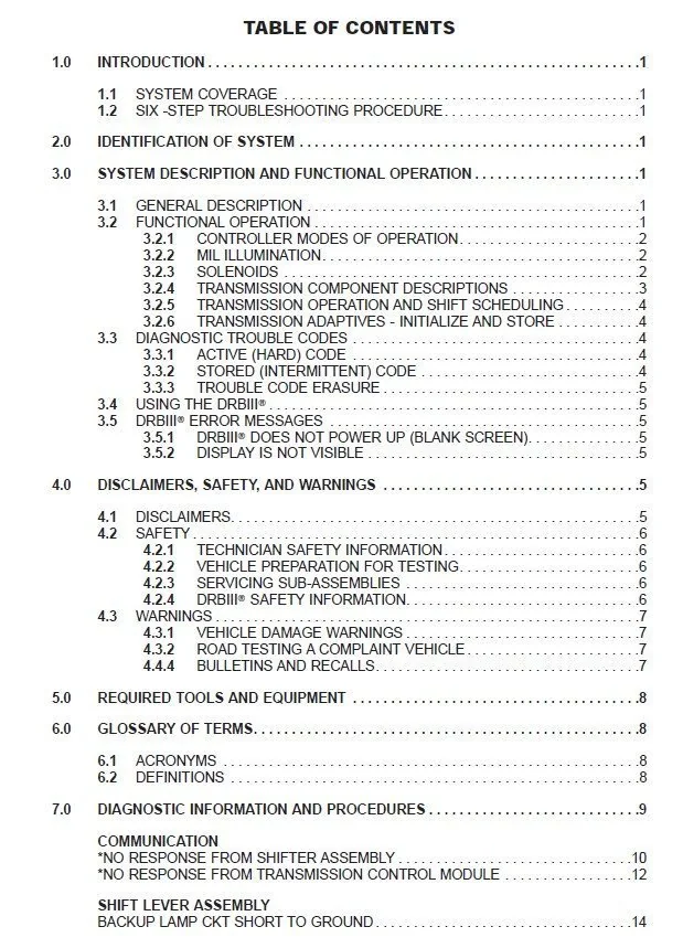
TABLE OF CONTENTS
1.0 INTRODUCTION . . . . . . . . . . . . . . . . . . . . . . . . . . . . . . . . . . . . . . . . . . . . . . . . . . . . . . . . .1
1.1 SYSTEM COVERAGE . . . . . . . . . . . . . . . . . . . . . . . . . . . . . . . . . . . . . . . . . . . . . . .1
1.2 SIX -STEP TROUBLESHOOTING PROCEDURE. . . . . . . . . . . . . . . . . . . . . . . . . .1
2.0 IDENTIFICATION OF SYSTEM . . . . . . . . . . . . . . . . . . . . . . . . . . . . . . . . . . . . . . . . . . . . .1
3.0 SYSTEM DESCRIPTION AND FUNCTIONAL OPERATION . . . . . . . . . . . . . . . . . . . . . .1
3.1 GENERAL DESCRIPTION . . . . . . . . . . . . . . . . . . . . . . . . . . . . . . . . . . . . . . . . . . . .1
3.2 FUNCTIONAL OPERATION . . . . . . . . . . . . . . . . . . . . . . . . . . . . . . . . . . . . . . . . . . .1
3.2.1 CONTROLLER MODES OF OPERATION. . . . . . . . . . . . . . . . . . . . . . . .2
3.2.2 MIL ILLUMINATION. . . . . . . . . . . . . . . . . . . . . . . . . . . . . . . . . . . . . . . . . .2
3.2.3 SOLENOIDS . . . . . . . . . . . . . . . . . . . . . . . . . . . . . . . . . . . . . . . . . . . . . . .2
3.2.4 TRANSMISSION COMPONENT DESCRIPTIONS . . . . . . . . . . . . . . . . .3
3.2.5 TRANSMISSION OPERATION AND SHIFT SCHEDULING . . . . . . . . . .4
3.2.6 TRANSMISSION ADAPTIVES – INITIALIZE AND STORE . . . . . . . . . . .4
3.3 DIAGNOSTIC TROUBLE CODES . . . . . . . . . . . . . . . . . . . . . . . . . . . . . . . . . . . . . .4
3.3.1 ACTIVE (HARD) CODE . . . . . . . . . . . . . . . . . . . . . . . . . . . . . . . . . . . . . .4
3.3.2 STORED (INTERMITTENT) CODE . . . . . . . . . . . . . . . . . . . . . . . . . . . . .4
3.3.3 TROUBLE CODE ERASURE . . . . . . . . . . . . . . . . . . . . . . . . . . . . . . . . . .5
3.4 USING THE DRBIIIT . . . . . . . . . . . . . . . . . . . . . . . . . . . . . . . . . . . . . . . . . . . . . . . . .5
3.5 DRBIIIT ERROR MESSAGES . . . . . . . . . . . . . . . . . . . . . . . . . . . . . . . . . . . . . . . . .5
3.5.1 DRBIIIT DOES NOT POWER UP (BLANK SCREEN). . . . . . . . . . . . . . .5
3.5.2 DISPLAY IS NOT VISIBLE . . . . . . . . . . . . . . . . . . . . . . . . . . . . . . . . . . . .5
4.0 DISCLAIMERS, SAFETY, AND WARNINGS . . . . . . . . . . . . . . . . . . . . . . . . . . . . . . . . . .5
4.1 DISCLAIMERS. . . . . . . . . . . . . . . . . . . . . . . . . . . . . . . . . . . . . . . . . . . . . . . . . . . . . .5
4.2 SAFETY . . . . . . . . . . . . . . . . . . . . . . . . . . . . . . . . . . . . . . . . . . . . . . . . . . . . . . . . . . .6
4.2.1 TECHNICIAN SAFETY INFORMATION. . . . . . . . . . . . . . . . . . . . . . . . . .6
4.2.2 VEHICLE PREPARATION FOR TESTING. . . . . . . . . . . . . . . . . . . . . . . .6
4.2.3 SERVICING SUB-ASSEMBLIES . . . . . . . . . . . . . . . . . . . . . . . . . . . . . . .6
4.2.4 DRBIIIT SAFETY INFORMATION. . . . . . . . . . . . . . . . . . . . . . . . . . . . . . .6
4.3 WARNINGS . . . . . . . . . . . . . . . . . . . . . . . . . . . . . . . . . . . . . . . . . . . . . . . . . . . . . . . .7
4.3.1 VEHICLE DAMAGE WARNINGS . . . . . . . . . . . . . . . . . . . . . . . . . . . . . . .7
4.3.2 ROAD TESTING A COMPLAINT VEHICLE . . . . . . . . . . . . . . . . . . . . . . .7
4.4.4 BULLETINS AND RECALLS. . . . . . . . . . . . . . . . . . . . . . . . . . . . . . . . . . .7
5.0 REQUIRED TOOLS AND EQUIPMENT . . . . . . . . . . . . . . . . . . . . . . . . . . . . . . . . . . . . . .8
6.0 GLOSSARY OF TERMS. . . . . . . . . . . . . . . . . . . . . . . . . . . . . . . . . . . . . . . . . . . . . . . . . . .8
6.1 ACRONYMS . . . . . . . . . . . . . . . . . . . . . . . . . . . . . . . . . . . . . . . . . . . . . . . . . . . . . . .8
6.2 DEFINITIONS . . . . . . . . . . . . . . . . . . . . . . . . . . . . . . . . . . . . . . . . . . . . . . . . . . . . . .8
7.0 DIAGNOSTIC INFORMATION AND PROCEDURES . . . . . . . . . . . . . . . . . . . . . . . . . . . .9
COMMUNICATION
*NO RESPONSE FROM SHIFTER ASSEMBLY . . . . . . . . . . . . . . . . . . . . . . . . . . . . . . .10
*NO RESPONSE FROM TRANSMISSION CONTROL MODULE . . . . . . . . . . . . . . . . .12
SHIFT LEVER ASSEMBLY
BACKUP LAMP CKT SHORT TO GROUND. . . . . . . . . . . . . . . . . . . . . . . . . . . . . . . . . .14
PLEASE NOTE:
- This is the SAME manual used by the dealers to troubleshoot any faults in your vehicle. This can be yours in 2 minutes after the payment is made.
- Contact us at heydownloadss @gmail.com should you have any queries before your purchase or that you need any other service / repair / parts operators manual.

Reviews
There are no reviews yet.