Description
2007 Evinrude E-TEC 75HP 90HP Outboard Service Repair Manual
This 2007 Evinrude E-TEC 75HP 90HP outboard service repair manual is a complete workshop guide for the 3-cylinder, 79 cubic inch E-TEC direct-injection platform. It covers every major system on these engines — the Engine Management Module (EMM), fuel injection, oiling, cooling, electrical and ignition, powerhead, midsection, gearcase, and trim/tilt — with the procedures, specifications, and diagrams a technician needs to service and repair these outboards correctly.
Written for qualified, factory-trained technicians familiar with Evinrude/Johnson special tools, the 2007 Evinrude E-TEC 75HP 90HP service manual is organized by system so you can go straight to the section relevant to the job. It is delivered as an instant PDF download, ready for use on any device and printable for the shop.
File Details
- Manual type: Service / Repair Manual
- Brand: Evinrude / Johnson
- Models covered: 75HP, 90HP E-TEC
- Model numbers: E75DPLSUM, E90DPLSUM, E90DPXSUM, E90DSLSUM
- Year: 2007
- Engine: In-line 3-cylinder, two-cycle, 79.1 cu in. (1296 cc)
- Language: English
- File format: PDF
- Page count: 344 pages
Chapters Covered
- Introduction — safety information, models covered, abbreviations, engine emissions information, nautical orientation, symbols
- Service Specifications and Special Tools — technical data, standard torque specifications, electrical/ignition tools, fuel system tools, gearcase tools, powerhead tools, universal tools, shop aids
- Installation and Predelivery — boat rigging, remote controls, battery installation, battery switches, battery and switch wiring diagrams, fuel system requirements, cable and hose installation, outboard installation, transom measuring and drilling, lifting the outboard, steering systems, outboard mounting, rigging, control cable adjustments, wiring harness connections, water pressure connection, fuel and oil priming, fuel requirements, oil requirements, running checks, propellers, final adjustments
- Maintenance — inspection and maintenance schedule, anti-corrosion protection, sacrificial anodes, cooling system, flushing, water intake screens, lubrication, steering system, swivel bracket, tilt tube, throttle and shift linkage, propeller shaft, gearcase lubricant, trim and tilt, battery, fuel and oil systems, fuel filter, oil reservoir, air silencer, hoses and connections, spark plugs, indexing, storage, pre-season service, submerged engines
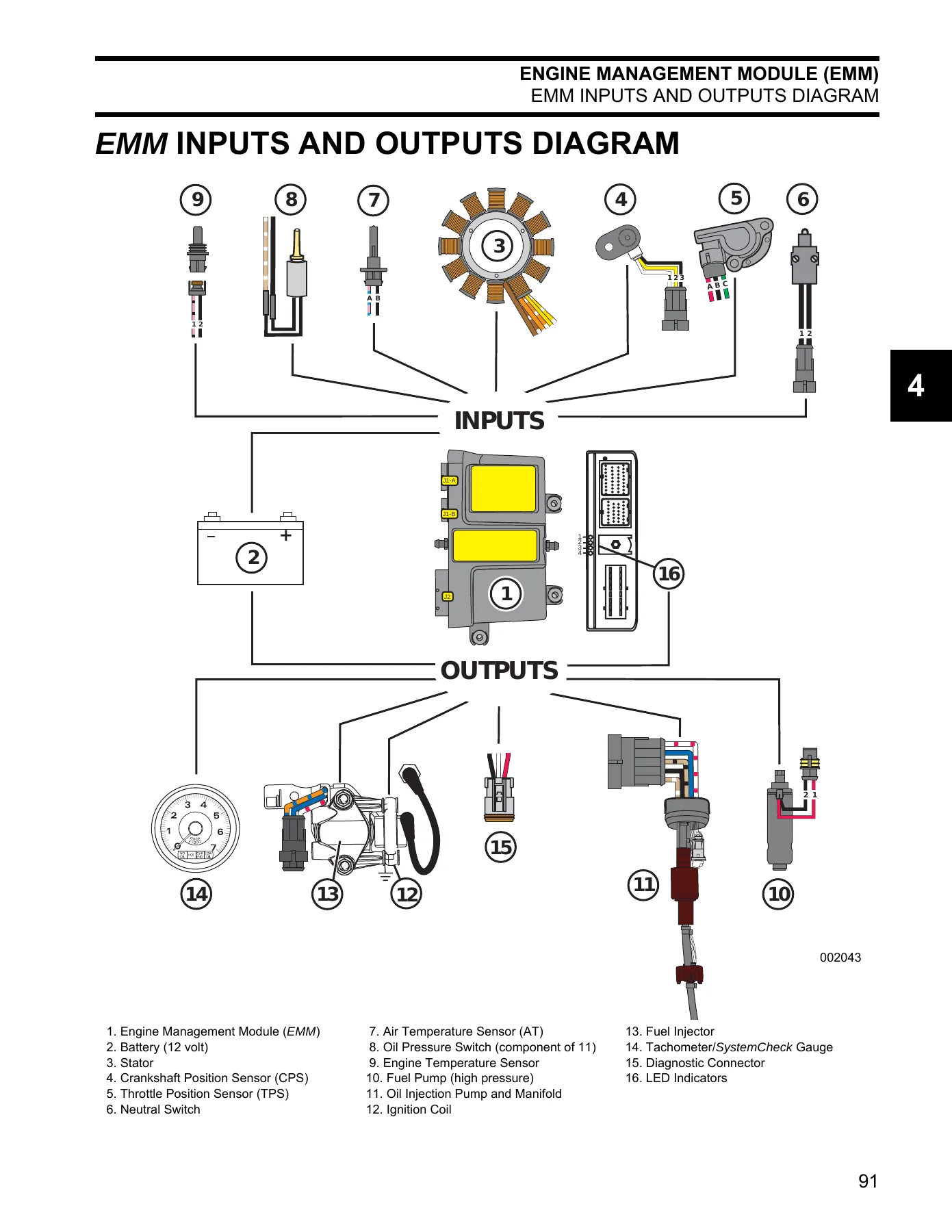
- Engine Management Module (EMM) — description, EMM functions, EMM connections, sensors and functions, internal sensors, external sensors, internal functions, EMM inputs and outputs diagram, S.A.F.E. warning system, shutdown mode, EMM diagnostics, LED indicators, diagnostic software programs, communication, program information, service codes, static tests, dynamic tests, oil control, starter mode, timing verification, TPS calibration, idle speed, fuel injector servicing, fuel control adjustment, reports, software replacement, EMM transfer, SystemCheck engine monitor
- System Analysis — electrical connections, ground circuits, fuse, EMM diagnostics, diagnostic procedures, symptoms, specialized test procedures, dynamic tests, testing with timing light, ignition system output, fuel injector/oil injection pump activation, inductive amp meter test, engine monitoring information, voltage testing, start circuit, ignition and electrical circuits, ignition output, system voltage, static spark test, running ignition tests, fuel delivery, manifold pressure test, vapor separator checks, fuel injector operation, neutral switch, static tests, dynamic tests
- Electrical and Ignition — service chart, dash connections, instrument harness, ignition system tests, sensor resistance tests, ignition coil tests, stator tests, capacitor test, charging system tests, 12 V charging circuit, 55 V alternator circuit, SystemCheck circuit tests, gauge self-test check, check engine circuit test, water temp/hot circuit test, low oil circuit test, no oil circuit, remote control switch tests, electric starter tests, starter solenoid test, no load current draw test, tilt/trim relay test, tachometer circuit tests, flywheel servicing, timing adjustments, timing pointer, timing verification, TPS calibration, spark plugs, electric starter servicing, connector servicing
- Fuel System — service chart, components, fuel lift pump, fuel filter, vapor separator, fuel circulation pump, fuel manifolds, fuel injectors, fuel system hose routing, direct injection electrical circuits, injector/circulation pump circuits diagram, fuel component tests, injectors, fuel supply, fuel component servicing, relieving fuel system pressure, fuel filter, fuel lift pump, vapor separator, fuel injectors, fuel manifolds, intake manifold
- Oiling System — components, oil tank assembly, electrical circuit (55 V), SystemCheck low and no oil warning signals, oiling system electrical diagram, cylinder and crankcase, oil supply and distribution diagram, oil recirculation system, recirculation hose diagram, priming, oiling rates, oil injection rate, break-in oiling, oiling system tests, oil injection pump static test, oil injection pump voltage test, oil injection pump circuit resistance test, oil flow tests, oil-to-fuel check valve test, low oil sending unit test, no oil warning test, oil component servicing, oil distribution hoses, oil tank assembly
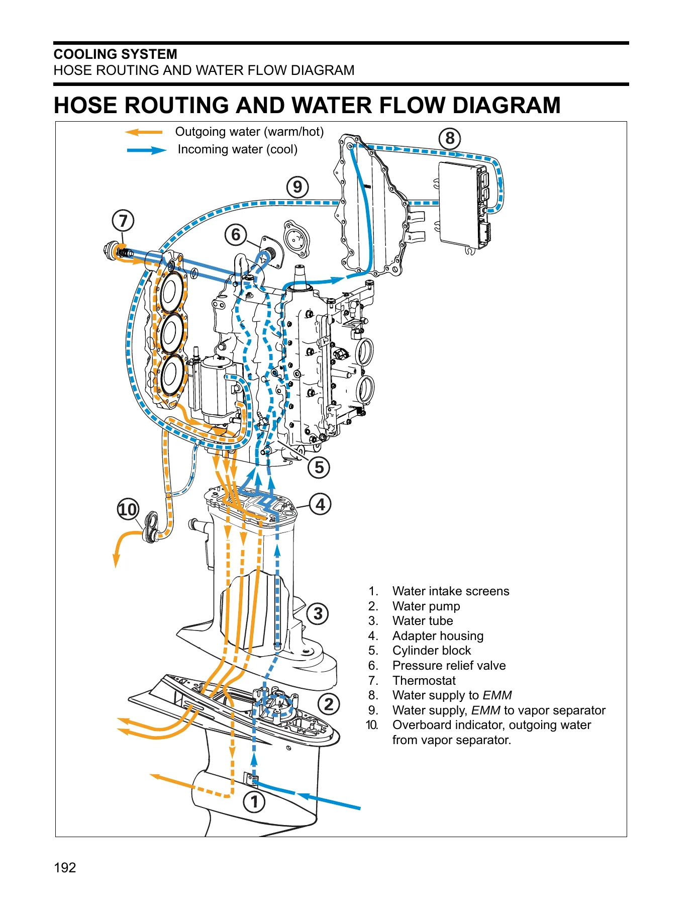
- Cooling System — engine temperature check, software method, pyrometer method, idle operating temperature troubleshooting, components, general description, water pump and intakes, water supply tube, adapter housing, pressure relief valve, thermostat, block venting, water pressure connection, operation, cylinder block/cylinder head cooling, EMM and vapor separator cooling, thermostat servicing, pressure relief valve servicing
- Powerhead — service chart, general, cylinder compression testing, retaining ring pliers, removal, disassembly, shift linkage, throttle linkage, crankcase, cylinder head, connecting rods and pistons, crankshaft, cleaning, inspection, cylinder head, crankshaft, cylinder bore, pistons, piston rings, bearings, assembly, crankshaft, pistons and connecting rods, cylinder head, crankshaft and connecting rods, crankcase, shift linkage, throttle linkage, upper mount servicing, installation, powerhead views
- Midsection — service chart, tilt tube, exhaust housing, stern bracket
- Gearcase — service chart, gearcase types, propeller, inspection, lubricant, draining, filling, leak test, removal and installation, water pump, shift rod adjustment, disassembly, pre-disassembly inspection, propeller shaft bearing housing removal, pinion gear and driveshaft removal, driveshaft service, shift housing/gear/propeller shaft removal, water intake screens, gearcase housing inspection, bearing and seal removal, shift housing, pinion gear bearing, driveshaft bearing housing, propeller shaft bearing housing, bearing and seal installation, driveshaft shimming, assembly
- Trim and Tilt — system description, manual adjustment, trailering bracket and tilt support, routine inspections, general, reservoir fluid, manual release valve, stern brackets, troubleshooting, electrical circuit tests, relay testing, trim and tilt motor current draw tests, trim and tilt motor no load test, trim gauge test, trim sender test, removal and installation, servicing, adjustments
- Safety — marine products and safety, outboard shift systems, speed control, steering control, fuel/electrical system, mounting system, hydraulic tilt/trim shock absorption, emergency stop system, safety awareness test
- Index
- Trouble Check Chart — outboard will not start, hard to start, will not shut off, starts and stalls, low maximum RPM, excessive smoking, surges/runs rough
- Diagrams — hose routing and water flow, MWS instrument wiring harness, lanyard switch/emergency stop circuits, MWS key switch and neutral safety switch, MWS dashboard, EMM LED diagnostic indicators, E-TEC 75-90HP wiring diagram
- EMM Service Code Chart — complete fault code reference
That is the full scope of the manual. The 2007 Evinrude E-TEC 75HP 90HP service repair manual covers the E-TEC platform in depth — the engine management system, the direct-injection fuel system, the oiling system, the cooling system, the electrical and ignition circuits, the powerhead, the midsection, the gearcase, and the trim/tilt unit. Each chapter includes the procedures, specifications, and illustrations needed to carry out service work, from simple maintenance to complete rebuilds.
What This Manual Helps You Do
The 2007 Evinrude E-TEC 75HP 90HP outboard repair manual supports a wide range of service tasks:
- Diagnose electrical and ignition faults using EMM LED indicators, diagnostic software, and circuit tests
- Retrieve and interpret service codes, including the complete EMM Service Code Chart
- Test fuel pressure, lift pump pressure, oil flow, and circulation pump operation
- Remove and reinstall fuel injectors, the vapor separator, and the fuel lift pump
- Service the oil tank, injection pump, distribution manifold, and oil recirculation circuits
- Rebuild the water pump and service the thermostat and pressure relief valve
- Remove the powerhead, disassemble the crankcase, service the crankshaft, connecting rods, pistons, and cylinder head, then reassemble and install
- Service the gearcase — bearing and seal replacement, driveshaft shimming, shift rod adjustment, water intake screens, and leak testing
- Remove and install the trim/tilt unit, service the hydraulic components, and test the electrical circuits
- Perform installation and predelivery rigging — remote control setup, battery wiring, cable routing, control cable adjustments, propeller selection and installation, and final adjustments
- Follow the maintenance schedule for inspection, lubrication, corrosion protection, and storage
- Use the correct torque values and special tools for each procedure
Complete PDF Bookmark Tree
Complete Bookmarks
The complete bookmarks in the “2007 Evinrude E-TEC 75HP 90HP Outboard Service Repair Manual – PDF Download” are as follows:
KEYWORD SEARCH
+INTRODUCTIONp. 5
+MODELS COVERED IN THIS MANUALp. 6
Identifying Model and Serial Numbersp. 6
MODEL DESIGNATIONp. 7
TYPICAL PAGE – Ap. 8
TYPICAL PAGE – Bp. 9
TYPICAL PAGE – Cp. 10
TYPICAL PAGE – Dp. 11
+ABBREVIATIONS USED IN THIS MANUALp. 12
Units of Measurementp. 12
List of Abbreviationsp. 12
+ENGINE EMISSIONS INFORMATIONp. 13
Manufacturer’s Responsibilityp. 13
Dealer’s Responsibilityp. 13
Owner’s Responsibilityp. 13
EPA Emission Regulationsp. 13
PRODUCT REFERENCE AND ILLUSTRATIONSp. 13
+SYMBOLSp. 14
Electricalp. 14
Valuesp. 15
+NOTESp. 16
Technician’s Notesp. 16
Related Documentsp. 16
+SERVICE SPECIFICATIONS AND SPECIAL TOOLSp. 17
TECHNICAL DATAp. 18
STANDARD TORQUE SPECIFICATIONSp. 20
+SPECIAL TOOLSp. 21
Electrical / Ignitionp. 21
Fuel Systemp. 22
Gearcasep. 22
Powerheadp. 24
Universalp. 25
SHOP AIDSp. 27
+INSTALLATION AND PREDELIVERYp. 31
+BOAT RIGGINGp. 32
Remote Controlsp. 32
Battery Installationp. 34
Battery Switches and Multiple Batteriesp. 35
Battery and Switch Wiring Diagramsp. 37
Fuel System Requirementsp. 39
Cable and Hose Installationp. 41
+OUTBOARD INSTALLATIONp. 46
Hull Preparationp. 46
Transom Measuring and Drillingp. 47
Drilling and Hardware Diagramp. 50
Lifting the Outboardp. 51
Steering Systemsp. 51
Outboard Mountingp. 53
+OUTBOARD RIGGINGp. 54
Cable, Hose, and Wire Routingp. 54
Control Cable Adjustmentsp. 54
Electrical Harness Connectionsp. 56
Water Pressure Gaugep. 56
+FUEL AND OIL PRIMINGp. 57
Fuel Requirementsp. 57
Fuel System Primingp. 58
Oil Requirementsp. 59
Oil Injection Ratep. 59
SystemCheck Low Oil Warning Testp. 59
Oil Supply Primingp. 60
Break-In Oilingp. 60
+BEFORE START-UPp. 61
Gearcase Lubricantp. 61
Oil Levelp. 61
Trim and Tilt Fluidp. 61
+RUNNING CHECKSp. 62
SystemCheck Operationp. 62
Fuel Systemp. 62
Emergency Stop / Key Switchp. 62
Remote Control Operationp. 62
Start-In-Gear Preventionp. 62
Tachometer Pulse Settingp. 63
Water Pump Overboard Indicatorp. 63
Operating Temperaturep. 63
Idle Speedp. 63
Break-Inp. 63
+PROPELLERSp. 64
Propeller Selectionp. 64
Propeller Hardware Installationp. 65
+FINAL ADJUSTMENTSp. 66
Tilt Limit Switch Adjustmentp. 66
Trim Sending Unit Adjustmentp. 67
Trim Tab Adjustmentp. 68
Dual-Outboard Alignmentp. 69
+NOTESp. 70
Technician’s Notesp. 70
Related Documentsp. 70
+MAINTENANCEp. 71
INSPECTION AND MAINTENANCE SCHEDULEp. 72
+ANTI-CORROSION PROTECTIONp. 73
Sacrificial Anodesp. 73
Testing Procedure – Continuityp. 73
Metallic Component Protectionp. 73
Exterior Finishesp. 73
+COOLING SYSTEMp. 74
Flushingp. 74
Water Intake Screensp. 75
Additional Maintenancep. 75
+LUBRICATIONp. 75
Steering Systemp. 75
Swivel Bracket and Trailering Bracketp. 76
Tilt Tubep. 76
Throttle and Shift Linkagep. 76
Propeller Shaftp. 77
Gearcase Lubricantp. 77
Trim and Tiltp. 78
BATTERY AND BATTERY CONNECTIONSp. 78
+FUEL AND OIL SYSTEMSp. 79
Fuel Filterp. 79
Oil Reservoirp. 79
Air Silencerp. 79
Hoses and Connectionsp. 79
+SPARK PLUGSp. 80
+STORAGEp. 81
Fuel System Treatmentp. 81
Internal Engine Treatmentp. 81
Additional Recommendationsp. 82
+PRE-SEASON SERVICEp. 82
Outboard Mounting Boltsp. 82
Gearcase Lubricantp. 82
Battery(s)p. 82
Power Trim and Tiltp. 82
Operational Checksp. 82
+SUBMERGED ENGINESp. 83
Engine Dropped Overboard (Not Running)p. 83
Engine Dropped Overboard (Running)p. 83
Engine Dropped Overboard (In Salt Water)p. 83
Prolonged Submersion (Fresh or Salt Water)p. 83
+NOTESp. 84
Technician’s Notesp. 84
Related Documentsp. 84
+ENGINE MANAGEMENT MODULE (EMM)p. 85
+DESCRIPTIONp. 86
EMM Functionsp. 86
EMM Connectionsp. 86
+SENSORS AND FUNCTIONSp. 87
Internal Sensorsp. 87
External Sensorsp. 88
Internal Functionsp. 90
EMM INPUTS AND OUTPUTS DIAGRAMp. 91
+S.A.F.E. WARNING SYSTEMp. 92
Activationp. 92
Recoveryp. 92
SHUTDOWN MODEp. 92
+EMM DIAGNOSTICSp. 93
LED Indicatorsp. 93
Diagnostic Software Programp. 94
Communicationp. 94
Program Informationp. 95
Service Codes (Faults)p. 95
Static Testsp. 96
Dynamic Testsp. 97
Oil Controlp. 98
Starter Mode (Tiller/Remote Programming)p. 98
Timing Verificationp. 98
TPS Calibrationp. 99
Idle Speedp. 99
Fuel Injector Servicingp. 99
Fuel Control Adjustmentp. 100
Reportsp. 100
Software Replacementp. 101
EMM Transferp. 101
+SystemCheck ENGINE MONITORp. 101
System Self-Testp. 102
Service Modep. 102
Engine Runningp. 102
+SYSTEM ANALYSISp. 103
ELECTRICAL CONNECTIONSp. 104
+GROUND CIRCUITSp. 106
FUSEp. 106
+EMM DIAGNOSTICSp. 107
LED Indicatorsp. 107
Software Programsp. 107
+DIAGNOSTIC PROCEDURESp. 108
+SPECIALIZED TEST PROCEDURESp. 110
Dynamic Testsp. 110
Testing with Timing Lightp. 110
Inductive Amp Meter Testp. 111
Engine Monitoring Informationp. 111
Voltage Testingp. 112
+START CIRCUITp. 112
Electric Starter Operationp. 112
Starter Solenoid Activationp. 113
+IGNITION AND ELECTRICAL CIRCUITSp. 114
Stop Circuitp. 114
Neutral Switchp. 114
Stator Output Voltagep. 114
EMMp. 114
Crankshaft Position Sensorp. 114
Alternator Output Voltagep. 114
Capacitorp. 114
Ignition Power Supply to EMMp. 114
Ignition Primary Voltagep. 114
Ignition Coilp. 114
+IGNITION OUTPUTp. 115
Wiring Inspectionp. 115
Ignition Voltagep. 115
System Voltagep. 116
Static Spark Testp. 116
Running Ignition Testsp. 117
Ignition Primary Circuit Resistance Testp. 118
Crankshaft Position Sensor (CPS) Testp. 118
+FUEL DELIVERYp. 119
Manifold Pressure Testp. 119
Vapor Separator Checksp. 120
Fuel Delivery to Lift Pumpp. 120
+FUEL INJECTOR OPERATIONp. 120
Neutral Switchp. 120
Static Testsp. 120
Dynamic Testsp. 121
+NOTESp. 122
Technician’s Notesp. 122
Related Documentsp. 122
+ELECTRICAL AND IGNITIONp. 123
SERVICE CHARTp. 124
DASH CONNECTIONS, INSTRUMENT HARNESSp. 126
+IGNITION SYSTEM TESTSp. 127
Sensor Resistance Testsp. 127
Ignition Coil Testsp. 128
Stator Testsp. 129
Capacitor Testp. 130
+CHARGING SYSTEM TESTSp. 130
12 V Charging Circuitp. 130
55 V Alternator Circuitp. 131
+SystemCheck CIRCUIT TESTSp. 132
Gauge Self-Test Checkp. 132
CHECK ENGINE Circuit Testp. 133
WATER TEMP/ HOT Circuit Testp. 133
LOW OIL Circuit Testp. 134
NO OIL Circuitp. 134
+REMOTE CONTROL SWITCH TESTSp. 134
Key Switch Testp. 134
Neutral Start Circuit Testp. 135
Neutral Start Switch Testp. 135
Emergency Stop Switch Testp. 136
+ELECTRIC STARTER TESTSp. 136
Starter Solenoid Testp. 136
No Load Current Draw Testp. 137
+TILT/TRIM RELAY TESTp. 138
Operationp. 138
Test Procedurep. 138
TACHOMETER CIRCUIT TESTSp. 139
+FLYWHEEL SERVICINGp. 140
Removalp. 140
Installationp. 141
+TIMING ADJUSTMENTSp. 142
Timing Pointerp. 142
Timing Verificationp. 143
TPS Calibrationp. 143
+SPARK PLUGSp. 144
Inspectionp. 144
Indexingp. 144
+ELECTRIC STARTER SERVICINGp. 145
Removalp. 145
Disassemblyp. 145
Cleaning and Inspectionp. 146
Assemblyp. 147
Installationp. 148
+CONNECTOR SERVICINGp. 149
DEUTSCH Connectorsp. 149
AMP Connectorsp. 150
Packard † Connectorsp. 152
+NOTESp. 154
Technician’s Notesp. 154
Related Documentsp. 154
+FUEL SYSTEMp. 155
SERVICE CHARTp. 156
+COMPONENTSp. 158
Fuel Lift Pumpp. 158
Fuel Filterp. 158
Vapor Separatorp. 158
Fuel Circulation Pumpp. 160
Fuel Manifoldsp. 160
Fuel Injectorsp. 161
FUEL SYSTEM HOSE ROUTINGp. 162
+DIRECT INJECTION ELECTRICAL CIRCUITSp. 163
Injector / Circulation Pump Circuits Diagramp. 163
+FUEL COMPONENT TESTSp. 164
Injectorsp. 164
Fuel Supplyp. 165
+FUEL COMPONENT SERVICINGp. 168
Relieving Fuel System Pressurep. 168
Fuel Filterp. 169
Fuel Lift Pumpp. 169
Vapor Separatorp. 170
Fuel Injectorsp. 170
Fuel Manifoldsp. 174
+INTAKE MANIFOLDp. 174
Removalp. 174
Disassemblyp. 174
Inspectionp. 175
Assemblyp. 175
Installationp. 176
+OILING SYSTEMp. 177
SERVICE CHARTp. 178
+COMPONENTSp. 179
Oil Tank Assemblyp. 179
Electrical Circuit (55 V)p. 180
SystemCheck LOW and NO OIL Warning Signalsp. 180
Oiling System Electrical Diagramp. 181
Cylinder and Crankcasep. 182
Oil Supply and Distribution Diagramp. 182
Oil Recirculation Systemp. 183
Recirculation Hose Diagramp. 183
PRIMINGp. 184
+OILING RATESp. 184
Oil Injection Ratep. 184
Break-in Oilingp. 184
+OILING SYSTEM TESTSp. 185
Oil Injection Pump Static Testp. 185
Oil Injection Pump Voltage Testp. 185
Oil Injection Pump Circuit Resistance Testp. 186
Oil Flow Testsp. 186
Oil-to-Fuel Check Valve Testp. 188
LOW OIL Sending Unit Testp. 188
NO OIL Warning Testp. 188
+OIL COMPONENT SERVICINGp. 189
Oil Distribution Hosesp. 189
Oil Tank Assemblyp. 190
+COOLING SYSTEMp. 191
HOSE ROUTING AND WATER FLOW DIAGRAMp. 192
+ENGINE TEMPERATURE CHECKp. 193
Software Methodp. 193
Pyrometer Methodp. 193
Idle Operating Temperature Troubleshooting (Below Range)p. 194
+COMPONENTSp. 195
General Descriptionp. 195
Water Pump and Intakesp. 195
Water Supply Tubep. 195
Adapter Housingp. 196
Pressure Relief Valvep. 196
Thermostatp. 197
Block Ventingp. 197
Water Pressure Connectionp. 197
+OPERATIONp. 198
Cylinder Block / Cylinder Head Coolingp. 198
EMM and Vapor Separator Coolingp. 198
+THERMOSTAT SERVICINGp. 199
Disassemblyp. 199
Inspectionp. 199
Assemblyp. 199
+PRESSURE RELIEF VALVE SERVICINGp. 200
Disassemblyp. 200
Inspectionp. 200
Assemblyp. 200
+POWERHEADp. 201
SERVICE CHARTp. 202
+GENERALp. 204
Cylinder Compression Testingp. 204
Retaining Ring Pliersp. 204
REMOVALp. 205
+DISASSEMBLYp. 207
Generalp. 207
Shift Linkagep. 207
Throttle Linkagep. 207
Crankcasep. 208
Cylinder Headp. 209
Connecting Rods and Pistonsp. 209
Crankshaftp. 210
CLEANINGp. 212
+INSPECTIONp. 213
Cylinder Headp. 213
Crankshaftp. 214
Cylinder Borep. 214
Pistonsp. 214
Piston Ringsp. 214
Bearingsp. 215
+ASSEMBLYp. 216
Crankshaftp. 216
Pistons and Connecting Rodsp. 218
Cylinder Headp. 220
Crankshaft and Connecting Rodsp. 221
Crankcasep. 224
Shift Linkagep. 226
Throttle Linkagep. 227
Generalp. 227
+UPPER MOUNT SERVICINGp. 228
Removalp. 228
Installationp. 228
INSTALLATIONp. 229
+POWERHEAD VIEWSp. 233
Port Short Blockp. 233
Starboard Short Blockp. 233
Port Dressed Powerheadp. 234
Starboard Dressed Powerheadp. 234
Frontp. 235
Rearp. 236
Topp. 237
+NOTESp. 238
Technician’s Notesp. 238
Related Documentsp. 238
+MIDSECTIONp. 239
SERVICE CHARTp. 240
+TILT TUBEp. 242
Removalp. 242
Installationp. 243
+EXHAUST HOUSINGp. 244
Removalp. 244
Disassemblyp. 244
Cleaning and Inspectionp. 246
Assemblyp. 246
Installationp. 249
+STERN BRACKETp. 249
Removalp. 249
Disassemblyp. 249
Assemblyp. 252
+GEARCASEp. 255
SERVICE CHARTp. 256
GEARCASE TYPESp. 258
+PROPELLERp. 258
+LUBRICANTp. 258
Drainingp. 258
Inspectionp. 259
Fillingp. 259
LEAK TESTp. 259
+REMOVAL AND INSTALLATIONp. 260
Removalp. 260
Installationp. 261
+WATER PUMPp. 262
Disassemblyp. 262
Inspectionp. 262
Assemblyp. 263
SHIFT ROD ADJUSTMENTp. 265
+DISASSEMBLYp. 266
Pre-Disassembly Inspectionp. 266
Propeller Shaft Bearing Housing Removalp. 267
Pinion Gear and Driveshaft Removalp. 267
Driveshaft Servicep. 269
Shift Housing, Gear and Propeller Shaft Removalp. 270
Water Intake Screensp. 270
GEARCASE HOUSING INSPECTIONp. 270
+BEARING AND SEAL REMOVALp. 271
Shift Housingp. 271
Pinion Gear Bearingp. 272
Driveshaft Bearing Housingp. 273
Propeller Shaft Bearing Housingp. 273
+BEARING AND SEAL INSTALLATIONp. 274
Shift Housingp. 274
Pinion Gear Bearingp. 276
Driveshaft Bearing Housingp. 277
Propeller Shaft Bearing Housingp. 278
DRIVESHAFT SHIMMINGp. 279
+ASSEMBLYp. 280
Water Intake Screensp. 280
Shift Housing, Gear, and Propeller Shaft Installationp. 280
Shift Rod Housing Installationp. 281
Pinion Gear and Driveshaft Installationp. 282
Propeller Shaft Bearing Housing and Gear Installationp. 283
+TRIM AND TILTp. 285
+SYSTEM DESCRIPTIONp. 286
Manual Adjustmentp. 286
Trailering Bracket And Tilt Supportp. 286
+ROUTINE INSPECTIONSp. 287
Generalp. 287
Reservoir Fluidp. 287
Manual Release Valvep. 287
Stern Bracketsp. 287
TROUBLESHOOTINGp. 288
+ELECTRICAL CIRCUIT TESTSp. 288
Relay Testingp. 288
Trim and Tilt Motor Current Draw Testsp. 288
Trim and Tilt Motor No Load Testp. 289
Trim Gauge Testp. 290
Trim Sender Testp. 291
+REMOVAL AND INSTALLATIONp. 291
Removalp. 291
Installationp. 293
+SERVICINGp. 294
Disassemblyp. 294
Assemblyp. 295
ADJUSTMENTSp. 296
+SAFETYp. 297
TABLE OF CONTENTSp. 297
+MARINE PRODUCTS AND THE SAFETY OF PEOPLE WHO USE THEMp. 299
Outboard Shift Systems and Safetyp. 300
Outboard Speed Control System and Safetyp. 301
Outboard Steering Control System and Safetyp. 302
Outboard Fuel, Electrical System, and Safetyp. 304
Outboard Mounting System and Safetyp. 307
If weakened, parts could fail later on the water, when not expectedp. 308
Outboard Hydraulic Tilt/Trim Shock Absorption System and Safetyp. 309
Outboard Emergency Stop System and Safetyp. 310
Summing upp. 312
+MARINE PRODUCTS AND THE SAFETY OF PEOPLE WHO FIX THEMp. 313
Handling Outboardsp. 313
Handling Lead/Acid Batteriesp. 317
Gasoline – Handle With Care!p. 318
Hazardous Productsp. 319
Safety Awareness Testp. 320
INDEXp. 321
+TROUBLE CHECK CHARTp. 329
OUTBOARD WILL NOT STARTp. 329
OUTBOARD WILL NOT STARTp. 330
OUTBOARD HARD TO STARTp. 331
OUTBOARD WILL NOT SHUT OFFp. 332
OUTBOARD STARTS AND STALLSp. 332
OUTBOARD STARTS, LOW MAXIMUM RPMp. 333
EXCESSIVE SMOKINGp. 333
OUTBOARD SURGES, RUNS ROUGHp. 334
DIAGRAMSp. 335
Technical Specifications and Diagnostic Data
The 2007 Evinrude E-TEC 75HP 90HP service manual includes the technical data needed to keep these engines within factory tolerances. The specifications chapter lists full throttle operating range, power output, idle RPM in gear and neutral, displacement, bore and stroke, crankshaft journal dimensions, piston ring end gap, fuel pressure, fuel lift pump pressure, maximum fuel inlet vacuum, minimum octane, battery requirements, alternator output, engine fuse, maximum temperature, thermostat opening, water pressure, ignition type, firing order, RPM limits, crankshaft position sensor air gap, spark plug type and gap, gear ratio, gearcase lubricant capacity, shift rod height, shift cable stroke, trim and tilt fluid capacity, trim range, and tilt range. Standard torque specifications are provided for common fastener sizes, and specific torque values are given throughout the procedures.
The manual also includes a Trouble Check Chart that maps symptoms — outboard will not start, hard to start, will not shut off, starts and stalls, low maximum RPM, excessive smoking, surges and runs rough — to possible causes and the procedures needed to diagnose them.
Instant PDF Delivery
The 2007 Evinrude E-TEC 75HP 90HP outboard service repair manual is delivered as an instant PDF download. There is no shipping, no waiting for a physical book, and no restrictions on where you use it. Open it on a laptop, tablet, or phone, or print the pages you need for the job. The PDF format makes it easy to search for specifications, print a procedure, or keep the entire manual on a shop computer. Whether you are maintaining your own outboard or running a service shop, this manual provides the complete technical reference for the 2007 Evinrude E-TEC 75HP and 90HP models.

Reviews
There are no reviews yet.