

★ TRUSTED BY 321,897+ PROFESSIONALS WORLDWIDE
๐Ÿข
Trusted Business
Verified & Licensed
๐Ÿ›ก๏ธ
Virus Free Files
100% Safe Downloads
๐Ÿ”’
Secure Payment
SSL Protected
โšก
Instant Delivery
Available Immediately
Sale!

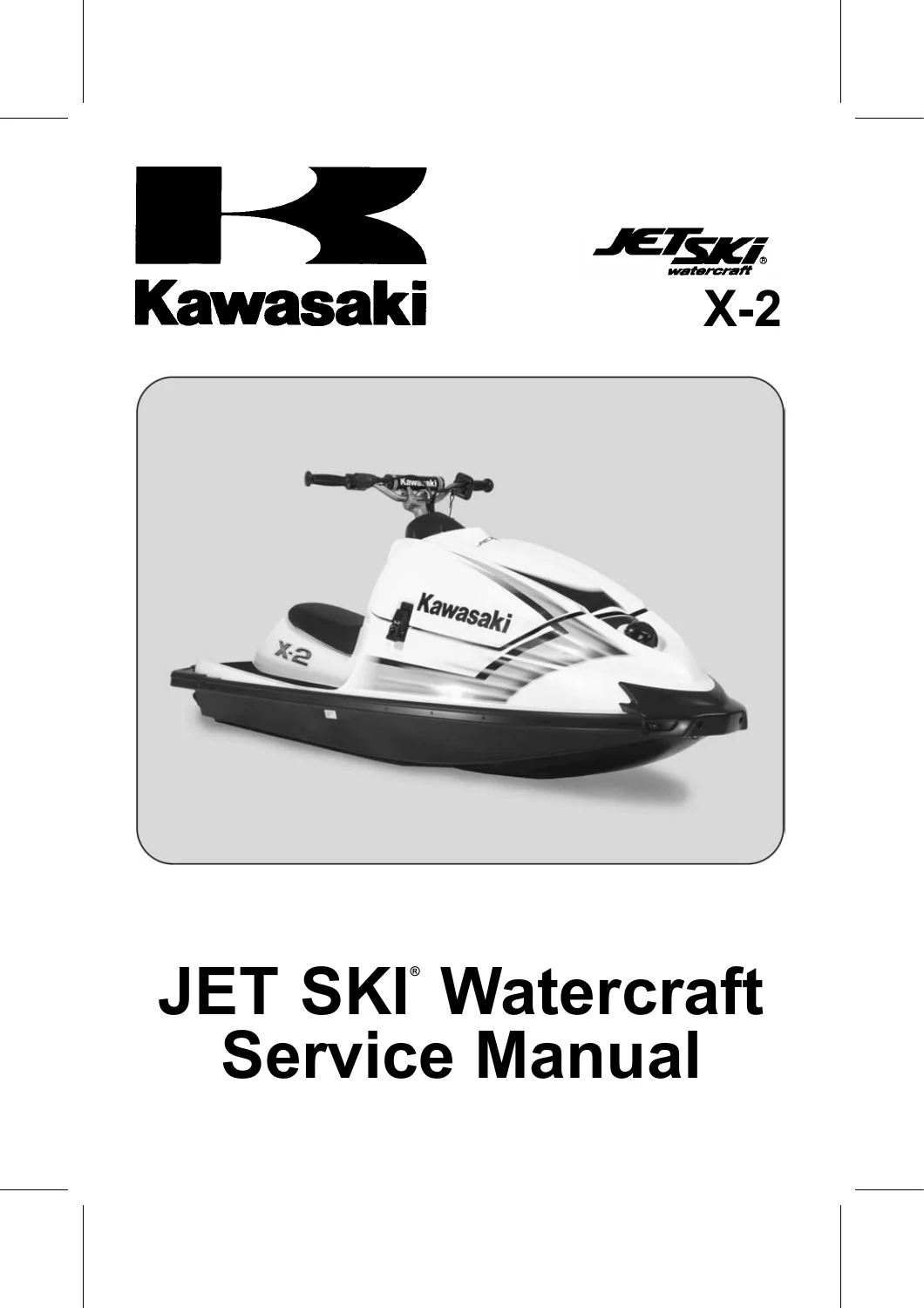
2007 Kawasaki X-2 JF800A7F Jet Ski Factory Service Manual – PDF Download

Original price was: $29.95.Current price is: $18.95.

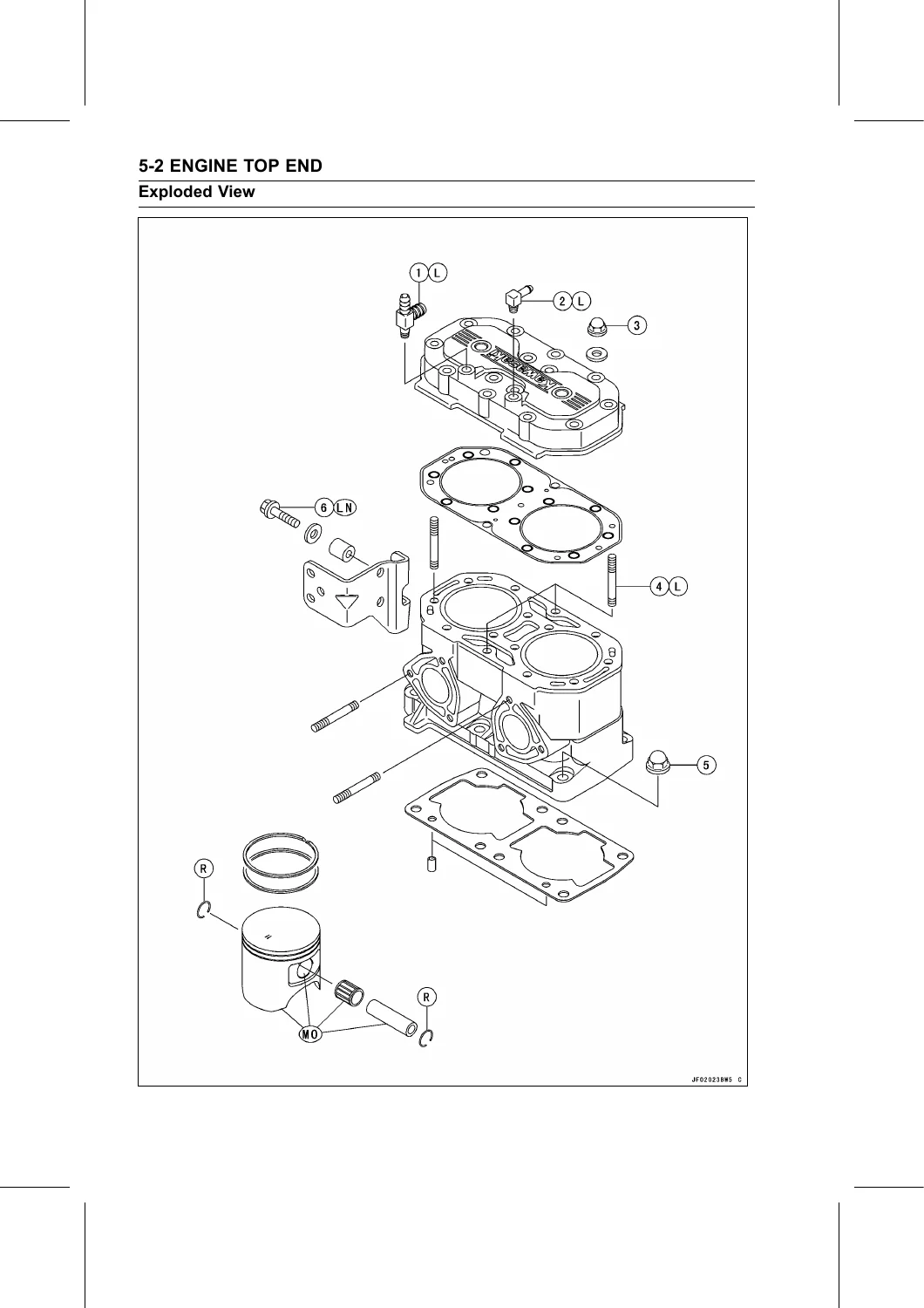
Factory service and repair manual for the 2007 Kawasaki X-2 JF800A7F Jet Ski. Covers engine, fuel, cooling, drive, pump, steering, electrical, and more. Includes specifications, torque values, and exploded view diagrams.

โšก
Instant PDF Download
Available immediately
๐Ÿ’พ
Save to Your Device
Download & keep forever
๐Ÿ›ก๏ธ
Antivirus Scanned
100% virus-free
๐ŸŒ
Trusted Worldwide
175,000+ customers

Description

Kawasaki X-2 JF800A7F Jet Ski 2007 Service Manual โ€“ PDF

This is the complete factory service manual for the 2007 Kawasaki X-2 JF800A7F Jet Ski, published by Kawasaki Heavy Industries. It provides the same diagnostic, repair, and overhaul procedures used by authorized Kawasaki dealers. Whether you are a professional marine technician or a dedicated owner, this manual gives you the detailed technical information needed to maintain, troubleshoot, and rebuild your Jet Ski correctly.

File Details

  • Manual Type: Factory Service Manual
  • Brand / Model: Kawasaki X-2 JF800A7F Jet Ski
  • Model Year: 2007
  • Language: English
  • Page Count: 247 pages (including covers and appendix)
  • File Format: PDF
  • Document Number: 99924-1383-01

Chapters Covered

The manual follows a logical system-by-system structure. Key sections and procedures include:

IMAGES PREVIEW

2007 Kawasaki X-2 JF800A7F Jet Ski Factory Service Manual - PDF Download โ€” PDF page 1 preview
2007 Kawasaki X-2 JF800A7F Jet Ski Factory Service Manual - PDF Download โ€” PDF page 44 preview
2007 Kawasaki X-2 JF800A7F Jet Ski Factory Service Manual - PDF Download โ€” PDF page 86 preview

  • General Information: Model identification, general specifications, unit conversion table, before servicing notes.
  • Periodic Maintenance: Maintenance chart, torque and locking agent tables, carburetor inspection and synchronization, throttle and choke cable adjustments, fuel filter and flame arrester cleaning, cooling and bilge flushing, impeller and steering cable inspection, spark plug and battery maintenance, general lubrication.
  • Fuel System: Exploded view, carburetor removal/disassembly/assembly/cleaning, pop-off pressure inspection, float arm level and diaphragm adjustment, fuel pump and filter service, flame arrester, inlet manifold and reed valve inspection, fuel tank and fuel tap procedures.
  • Exhaust System: Expansion chamber, exhaust manifold, water box muffler, removal and installation procedures.
  • Engine Top End: Cylinder head, cylinder, piston and ring inspection, compression measurement, cylinder head warp and cylinder wear inspection, piston diameter measurement, cylinder boring/honing, ring end gap.
  • Engine Removal/Installation: Engine mount removal and installation, shim selection, engine bed alignment.
  • Engine Bottom End: Coupling, magneto flywheel, stator, crankcase splitting and assembly, crankshaft maintenance (runout, connecting rod bend/twist, bearing clearance).
  • Cooling and Bilge Systems: Flow diagram, breather and bilge filter removal/cleaning, hose routing and inspection.
  • Drive System: Drive shaft and holder removal/installation, runout inspection, seal and bearing replacement.
  • Pump and Impeller: Exploded view, pump removal/disassembly/assembly, impeller outside diameter measurement, impeller clearance inspection, bearing and seal replacement.
  • Steering: Steering cable adjustment/removal/installation, handlebar and steering neck removal/installation.
  • Hull/Engine Hood: Hood opening/closing, latch, seat, bumper, and fitting removal/installation, hull replacement overview, rubber parts cementing.
  • Electrical System: Battery management and charging, electric starter system (starter motor, relay, reduction gear), charging system (regulator/rectifier, charging coil), ignition system (CDI, ignition coil, crankshaft sensor, spark plugs), electric case, switches, water and inlet air temperature sensors, fuse.
  • Storage: Preparation for storage (cooling, bilge, fuel, engine, battery, lubrication) and removal from storage procedures.
  • Appendix: Cable, wire, and hose routing diagrams; troubleshooting tables for starting difficulty, misfires, low power, overheating, and steering issues.

This comprehensive service manual provides step-by-step procedures, detailed exploded views, and precision specifications that are essential for any major repair, from simple maintenance to a complete engine rebuild or pump overhaul. The 2007 Kawasaki X-2 JF800A7F Jet Ski service manual is a technical reference that ensures your repairs are done to factory standards, with correct torque settings, clearances, and diagnostic procedures.

Complete PDF Bookmark Tree

Complete Bookmarks

The complete bookmarks in the โ€œ2007 Kawasaki X-2 JF800A7F Jet Ski Factory Service Manual – PDF Downloadโ€ are as follows:

tablesp. 1
LIST OF ABBREVIATIONSp. 6
Required cooling water for the enginep. 11
Units of Mass:p. 20
Units of Volume:p. 20
Units of Force:p. 20
Units of Length:p. 20
Units of Torque:p. 20
Units of Pressure:p. 20
Units of Speed:p. 20
Units of Power:p. 20
General Fasteners (stainless bolt and nut)p. 25
Idle Speedp. 27
Battery Terminal Voltagep. 37
Spark Plug Gapp. 38
Pop-off Pressurep. 64
Float Arm Levelp. 65
Reed Warpp. 70
Cylinder Compression (Usable Range)p. 93
Cylinder Head Warpp. 94
Cylinder Inside Diameterp. 94
Piston Diameterp. 95
Piston/Cylinder Clearancep. 95
Oversize Pistons and Ringsp. 95
Piston Ring End Gapp. 96
Shim Selectionp. 103
Connecting Rod Bendp. 116
Connecting Rod Twistp. 116
Connecting Rod Big End Radial Clearancep. 117
Connecting Rod Big End Side Clearancep. 117
Crankshaft Runout (Either Location)p. 117
Pop Rivet Removal Drill Bit Sizep. 124
Drive Shaft Runoutp. 136
Impeller Outside Diameterp. 146
Pump Case Inside Diameterp. 146
Impeller Clearancep. 147
Rivet Removal Drill Bit Sizep. 172
Terminal Voltage: 11.5 โˆผ less than 12.8 Vp. 190
Terminal Voltage: less than 11.5 Vp. 190
Starter Motor Brush Lengthp. 194
Commutator Diameterp. 195
Charging Coil Output Voltagep. 198
Charging Coil Resistancep. 198
Regulator/rectifier Resistancep. 199
Crankshaft Sensor Resistancep. 200
3 Needle Arcing Distancep. 201
Winding Resistancep. 202
Primary Lead Connectionsp. 203
Ignition Coil Primary Peak Voltagep. 203
Crankshaft Sensor Peak Voltagep. 204
Start Switch Resistancep. 211
Stop Switch Resistancep. 211
Water Temperature Sensor Resistancep. 213
Inlet Air Temperature Sensor Resistancep. 214
tocp. 1
Read OWNER'S MANUAL before operating.p. 6
MAINTENANCE AND ADJUSTMENTSp. 7
EMISSION CONTROL INFORMATIONp. 7
Forewordp. 8
General Informationp. 9
Before starting to service a watercraft, careful reading of thep. 10
Adjustmentsp. 10
Auxiliary Coolingp. 10
Battery Cablesp. 11
Edges of Partsp. 12
Cleaning solutionp. 12
Cleaning Watercraft before Disassemblyp. 12
Arrangement and Cleaning of Removed Partsp. 12
Storage of Removed Partsp. 12
Inspectionp. 13
Replacement Partsp. 13
Installation, Assemblyp. 13
Tightening Sequencep. 13
Torquep. 14
Forcep. 14
Gasket, O-Ringp. 14
Liquid Gasket, Locking Agentp. 14
Pressp. 14
Ball bearingp. 15
Oil Seal, Grease Sealp. 15
Lubricationp. 15
Circlips, Cotter Pinsp. 16
Direction of Engine Rotationp. 16
Electrical Leadsp. 16
Instrumentp. 16
JF800-A1 Left Side Viewp. 17
JF800-A1 Right Side Viewp. 17
Hull No.p. 17
Engine No.p. 17
Prefixes for Units:p. 20
Units of Temperature:p. 20
Periodic Maintenancep. 21
The scheduled maintenance must be done in accordance with this cp. 22
The following tables list the tightening torque for the major fap. 23
Fuel Systemp. 27
Carburetor Inspectionp. 27
Torque –p. 29
Torque –p. 29
Fuel Filter Screen Cleaningp. 29
Fuel Vent Check Valve Inspectionp. 30
Flame Arrester Cleaning and Inspectionp. 31
Torque –p. 32
Carburetor Throttle Shaft Spring Inspectionp. 32
Engine Bottom Endp. 33
Coupling Damper Inspectionp. 33
Cooling and Bilge Systemsp. 33
Cooling System Flushingp. 33
Bilge System Flushingp. 34
Pump and Impellerp. 35
Impeller Inspectionp. 35
Steeringp. 35
Steering Cable Inspectionp. 35
Steering Cable Lubricationp. 36
Handlebar Pivot Lubricationp. 36
Hull/Engine Hoodp. 36
Hull Drain Plug Inspectionp. 36
Electrical Systemp. 37
Battery Charging Condition Inspectionp. 37
Battery Terminals Inspectionp. 37
Spark plugs inspectionp. 37
General Lubricationp. 38
Nuts, Bolts, and Fasteners Tightness Inspectionp. 40
Hose and Hose Connection Inspectionp. 41
Rubber Strap Inspectionp. 42
Fuel Systemp. 43
Watercraft Strap Tool:p. 49
Throttle Cable Adjustmentp. 51
Throttle Case Removal/Disassemblyp. 51
Throttle Case Assembly/Installationp. 52
Torque –p. 53
Throttle Cable Removalp. 53
Throttle Cable Installationp. 54
Throttle Case and Cable Lubricationp. 54
Throttle Cable Inspectionp. 54
Choke Cable Adjustmentp. 55
Choke Cable Removalp. 55
Choke Cable Inspectionp. 55
Choke Cable Lubricationp. 55
Choke Knob Removalp. 55
Choke Knob Installationp. 56
Idle Speed Adjustmentp. 57
Mixture Screw Adjustmentp. 57
High Altitude Performance Adjustmentp. 57
Carburetor Synchronizationp. 57
Carburetor Removalp. 58
Carburetor Installationp. 59
Torque –p. 59
Torque –p. 59
Carburetor Disassemblyp. 59
Carburetor Assemblyp. 61
Torque –p. 61
Torque –p. 62
Torque –p. 62
Torque –p. 62
Torque –p. 62
Carburetor Cleaning and Inspectionp. 63
Pop-off Pressure Inspectionp. 64
Float Arm Level and Diaphragm Inspection and Adjustmentp. 65
Fuel Pump Removalp. 66
Fuel Pump Installationp. 67
Fuel Filter Inspection and Cleaningp. 67
Flame Arrester Removalp. 68
Flame Arrester Installationp. 68
Flame Arrester Cleaningp. 68
Inlet Manifold and Reed Valve Removalp. 69
Inlet Manifold and Reed Valve Installationp. 69
Torque –p. 69
Reed Valve Inspectionp. 70
Reed Valve Holder Inspectionp. 70
Reed Valve Stop Inspectionp. 70
Fuel Tank Removalp. 71
Special Tool –p. 72
Fuel Tank Installationp. 73
Torque –p. 73
Fuel Tank Cleaningp. 73
Fuel Filler and Tube Removalp. 74
Fuel Filler and Hose Installationp. 74
Fuel Filter Screen Cleaningp. 74
Fuel Tap Removalp. 75
Fuel Tap Installationp. 75
Fuel Tap Cleaningp. 75
Exhaust Systemp. 77
Expansion Chamber Removalp. 80
Expansion Chamber Installationp. 81
Torque –p. 81
Torque –p. 81
Expansion Chamber Cleaning and Inspectionp. 81
Exhaust Manifold Removalp. 82
Exhaust Manifold Installationp. 82
Torque –p. 82
Exhaust Manifold Cleaning and Inspectionp. 82
Water Box Muffler Removalp. 83
Water Box Muffler Inspectionp. 83
Engine Top Endp. 85
Compression Gauge, 20 kgf/cm :p. 89
Disassembly and Assemblyp. 90
Disassemblyp. 90
Special Tool –p. 90
Assemblyp. 91
Special Tools –p. 91
Torque –p. 92
Torque –p. 92
Torque –p. 92
Torque –p. 92
Maintenance and Inspectionp. 93
Compression Measurementp. 93
Special Tools –p. 93
Cylinder Head Warp Inspectionp. 94
Cylinder Wear Inspectionp. 94
Piston Diameter Measurementp. 95
Piston/Cylinder Clearance Inspectionp. 95
Boring and Honingp. 95
Piston Ring, Piston Ring Groove Inspectionp. 96
Piston Ring End Gap Inspectionp. 96
Engine Removal/Installationp. 97
Engine Removalp. 100
Engine Mount Removalp. 102
Engine Mount Installationp. 102
Torque –p. 102
Engine Installationp. 102
Torque –p. 103
Torque –p. 103
Engine Bottom Endp. 105
Coupling Holder:p. 109
Removalp. 110
Special Tools –p. 110
Installationp. 110
Torque –p. 110
Coupling Damper Inspectionp. 110
Removalp. 111
Special Tool –p. 111
Installationp. 111
Torque –p. 111
Torque –p. 111
Removalp. 112
Installationp. 113
Splittingp. 114
Assemblyp. 114
Sealant –p. 115
Torque –p. 115
The crankshaft changes the reciprocating motor of the piston intp. 116
Connecting Rod Bend/Twist Inspectionp. 116
Connecting Rod Big End Radial Clearance Inspectionp. 117
Connecting Rod Big End Side Clearance Inspectionp. 117
Crankshaft Main Bearing Wear Inspectionp. 117
Crankshaft Runout Inspectionp. 117
Crankshaft Assembly Specificationsp. 118
Cooling and Bilge Systemsp. 119
Breather Removalp. 124
Breather Installationp. 124
Breather Cleaning and Inspectionp. 125
Bilge Filter Removalp. 125
Bilge Filter Cleaning and Inspectionp. 125
Hose Removalp. 126
Hose Installationp. 126
Hose Inspectionp. 126
Cooling System Flushingp. 127
Bilge System Flushingp. 127
Drive Systemp. 129
Bearing Driver Set:p. 133
Drive Shaft Removal/Installationp. 134
Special Tool –p. 134
Torque –p. 134
Drive Shaft Holder Removal/Disassemblyp. 134
Special Tool –p. 135
Drive Shaft Holder Assembly/Installationp. 135
Special Tool –p. 135
Sealant –p. 135
Torque –p. 135
Drive Shaft Runoutp. 136
Pump and Impellerp. 137
Oil Seal & Bearing Remover:p. 141
Pump Removalp. 142
Pump Installationp. 142
Torque –p. 143
Torque –p. 143
Pump Disassemblyp. 143
Special Tool –p. 144
Special Tools –p. 144
Pump Assemblyp. 145
Special Tool –p. 145
Torque –p. 145
Torque –p. 146
Pump and Impeller Inspectionp. 146
Impeller Outside Diameter Measurementp. 146
Impeller Clearance Inspectionp. 147
Steeringp. 149
Box Wrench (27 mm)๏ผšp. 152
Steering Cable Adjustmentp. 153
Steering Cable Removalp. 153
Special Tool –p. 154
Torque –p. 154
Steering Cable Installationp. 155
Torque –p. 155
Torque –p. 155
Steering Cable Inspectionp. 155
Steering Cable Lubricationp. 155
Hand Grip Removal/Installationp. 156
Handlebar Removalp. 156
Handlebar Installationp. 156
Torque –p. 156
Torque –p. 157
Steering Removalp. 158
Steering Installationp. 159
Torque –p. 159
Special Tool –p. 159
Torque –p. 160
Torque –p. 160
Torque –p. 160
Hull/Engine Hoodp. 161
Engine Hood Openingp. 166
Engine Hood Closingp. 166
Engine Hood Removalp. 167
Engine Hood Installationp. 168
Latch Removalp. 168
Latch Installationp. 169
Catch Removalp. 169
Catch Installationp. 169
Tool Holder Removalp. 169
Tool Holder Installationp. 169
Seat Removalp. 170
Seat Installationp. 170
Battery Bracket Removalp. 170
Battery Bracket Installationp. 170
Electric Case Bracket Removalp. 171
Electric Case Bracket Installationp. 171
Seat Hook Removalp. 171
Seat Hook Installationp. 171
Drain Plug Housing Removalp. 172
Drain Plug Housing Installationp. 172
Exhaust Outlet Removalp. 172
Exhaust Outlet Installationp. 172
Rivet Removalp. 172
Rivet Installationp. 173
Front Bumper Removalp. 173
Front Bumper Installationp. 173
Corner Bumper Removalp. 173
Corner Bumper Installationp. 173
Side Bumper Removalp. 174
Side Bumper Installationp. 174
Rear Bumper Removalp. 175
Rear Bumper Installationp. 175
NOTEp. 177
Rubber Parts Locationp. 177
Electrical Systemp. 179
Hand Tester:p. 185
JF800-Ap. 186
Battery Removalp. 187
Battery Installationp. 187
Battery Managementp. 187
Precautionsp. 189
1)p. 189
2)p. 189
3)p. 189
4)p. 189
Interchangep. 190
Charging Condition Inspectionp. 190
Refreshing Chargep. 190
Reduction Gear Removal/Installationp. 192
Reduction Gear Inspectionp. 192
Starter Motor Removalp. 192
Starter Motor Installationp. 193
Torque –p. 193
Starter Motor Disassemblyp. 193
Starter Motor Assemblyp. 194
Torque –p. 194
Brush Inspectionp. 194
Brush Spring Inspectionp. 194
Commutator Cleaning and Inspectionp. 195
Armature Inspectionp. 195
Brush Plate Inspectionp. 195
Brush and Lead Assembly Inspectionp. 196
Starter Relay Removalp. 196
Starter Relay Installationp. 196
Starter Relay Inspectionp. 197
Special Tool –p. 197
Charging System Inspectionp. 198
Regulator/Rectifier Removalp. 198
Regulator/Rectifier Installationp. 199
Torque –p. 199
Regulator/rectifier Inspectionp. 199
WARNINGp. 200
Crankshaft Sensor Inspectionp. 200
Special Tool –p. 200
Ignition Coil Removalp. 200
Ignition Coil Installationp. 201
Torque –p. 201
Ignition Coil Inspectionp. 201
CDI Igniter Removalp. 202
CDI Igniter Installationp. 202
Torque –p. 202
Ignition Coil Primary Peak Voltage Inspectionp. 203
Special Tools –p. 203
Crankshaft Sensor Peak Voltage Inspectionp. 204
Special Tools –p. 204
Spark Plug Removalp. 204
Spark Plug Installationp. 204
Torque –p. 204
Spark Plug inspectionp. 205
Spark Plug Adjustmentp. 205
Spark Plug Cleaningp. 205
Electric Case Removalp. 207
Electric Case Installationp. 207
Torque –p. 207
Electric Case Disassemblyp. 207
Torque –p. 208
Torque –p. 209
Torque –p. 209
Start/Stop Switch Removalp. 210
Start/Stop Switch Installationp. 210
Torque –p. 210
Start/Stop Switch Inspectionp. 211
Special Tool –p. 211
A water temperature sensor is installed on the exhaust pipe. Whep. 212
Water Temperature Sensor Removalp. 212
Water Temperature Sensor Installationp. 212
Torque –p. 212
Water Temperature Sensor Inspectionp. 213
Special Tool –p. 213
Inlet Air Temperature Sensor Removalp. 214
Inlet Air Temperature Sensor Installationp. 214
Inlet Air Temperature Sensor Inspectionp. 214
Special Tool –p. 214
Switch Inspectionp. 215
Special Tool –p. 215
Start Switchp. 215
Stop Switchp. 215
Tether Switchp. 215
Fuse Inspectionp. 216
Storagep. 217
During the winter, or whenever the watercraft will not be in usep. 218
Cooling Systemp. 218
Bilge Systemp. 218
Fuel Systemp. 218
Torque –p. 219
Enginep. 219
Batteryp. 219
Lubricationp. 219
Generalp. 220
Lubricationp. 221
General Inspectionp. 221
Fuel Systemp. 221
Test Runp. 222
Appendixp. 223
Starting difficulty or failure to startp. 244
Ignition Systemp. 244
Sparkp. 244
No sparkp. 244
Fuel system (check that fuel tank contains fuel)p. 244
Outside Carburetorp. 244
Inside Carburetorp. 244
Battery/Starter Systemp. 244
Engine starts but stops right awayp. 244
Compressionp. 244
Fuel Systemp. 244
Outside Carburetorp. 244
Inside Carburetorp. 244
Electrical Systemp. 244
Engine misfires, does not run smoothlyp. 245
Fuel Systemp. 245
Fuel mixture too leanp. 245
Fault in Carburetorp. 245
Otherp. 245
Fuel mixture too richp. 245
Fault in Carburetorp. 245
Otherp. 245
Electrical Systemp. 245
Otherp. 245
Weak Sparkp. 245
Abnormal engine soundp. 245
During normal cruisingp. 245
During sudden accelerationp. 245
Pingingp. 245
When the engine is idling while coldp. 245
Low engine power (This trouble often has more than one cause, anp. 246
Ignition Systemp. 246
Fuel Systemp. 246
Otherp. 246
Overheatingp. 246
Heavy Fuel Consumptionp. 246
Poor performance though engine runs properlyp. 246
Jet Pumpp. 246
Poor steering control (Since faulty steering is dangerous, thisp. 246
Handlebar pivot nut too tightp. 246

Why You Need This Manual

With this 2007 Kawasaki X-2 JF800A7F Jet Ski service manual, you can confidently tackle repairs and maintenance that would otherwise require a costly trip to the dealership. The manual covers everything from carburetor synchronization to impeller clearance inspection, from electrical system diagnosis to engine bottom-end rebuilding. The included specifications (including torque values, service limits, and capacities) give you the exact data needed to make accurate adjustments and avoid expensive mistakes. Having the factory manual on hand means you are not guessingโ€”you are following the same instructions that Kawasaki technicians use.

This is a digital PDF available for instant download after purchase. It can be viewed on any computer, tablet, or smartphone, and can be printed for use in your workshop. No shipping fees, no waitingโ€”get the technical knowledge you need right now to keep your 2007 Kawasaki X-2 running at its best.

Reviews

There are no reviews yet.

Be the first to review “2007 Kawasaki X-2 JF800A7F Jet Ski Factory Service Manual – PDF Download”

What Our Customers Say

โ˜…โ˜…โ˜…โ˜…โ˜… Live reviews from customers
Loading customer reviews...
0
    0
    Your Cart
    Your cart is emptyReturn to Shop
    ๐Ÿ›’
    Recently Purchased
    ๐Ÿ•’ verified order