
2007 Volvo S40 (04-), V50, C70 (06-) Wiring Diagram Manual – TP 3999202
Original price was: $34.95.$20.95Current price is: $20.95.
Detailed 2007 Volvo wiring diagram manual covering S40 (04-), V50 and C70 (06-) electrical systems. TP 3999202 contains electrical distribution, fuses, relays, grounds, control modules, CAN/LIN/MOST networks, engine management circuits, lighting, body electronics, climate control, connectors, harness routing and component illustrations across 324 pages.
Description
2007 Volvo S40 (04-), V50, C70 (06-) Wiring Diagram Manual – TP 3999202
The 2007 Volvo S40 (04-), V50, C70 (06-) Wiring Diagram Manual – TP 3999202 is a detailed electrical reference for the S40 (04-), V50 and C70 (06-) configurations covered by this publication. Across 324 pages, the manual maps power distribution, fuses, relays, grounds, control modules, data networks and individual electrical systems, then extends into connector information, branching points, cable-harness routing, component illustrations and a component index. It is designed around circuit-level information, making it especially useful when tracing an electrical path, identifying the modules and connectors involved in a system, locating a ground or branching point, or following power and signal connections through the vehicle.
File Details
- Manual type: Wiring Diagram Manual
- Brand: Volvo
- Models: S40 (04-), V50, C70 (06-)
- Document number: TP 3999202
- Publication year: 2007
- Language: English
- Pages: 324
- File format: PDF
Electrical Information Built for Circuit Tracing
This Volvo S40 V50 C70 wiring diagram manual begins by explaining the notation used throughout the diagrams. Components use two-part designations, while separate sections identify branching points, connectors, electrical distribution and component locations. The symbol guide explains system voltage, wired and chassis grounds, screened wire, junction points, twisted cable, electrical connections, variants, CAN and LIN communication, MOST communication and connections between cable harnesses. A list of component type numbers distinguishes batteries, relays, switches, control modules, motors, sensors, actuators, heating elements, lights, fuses, distribution boxes, audio equipment, diagnostics connections, meters, ignition components, optics, grounds, branching points and connectors.
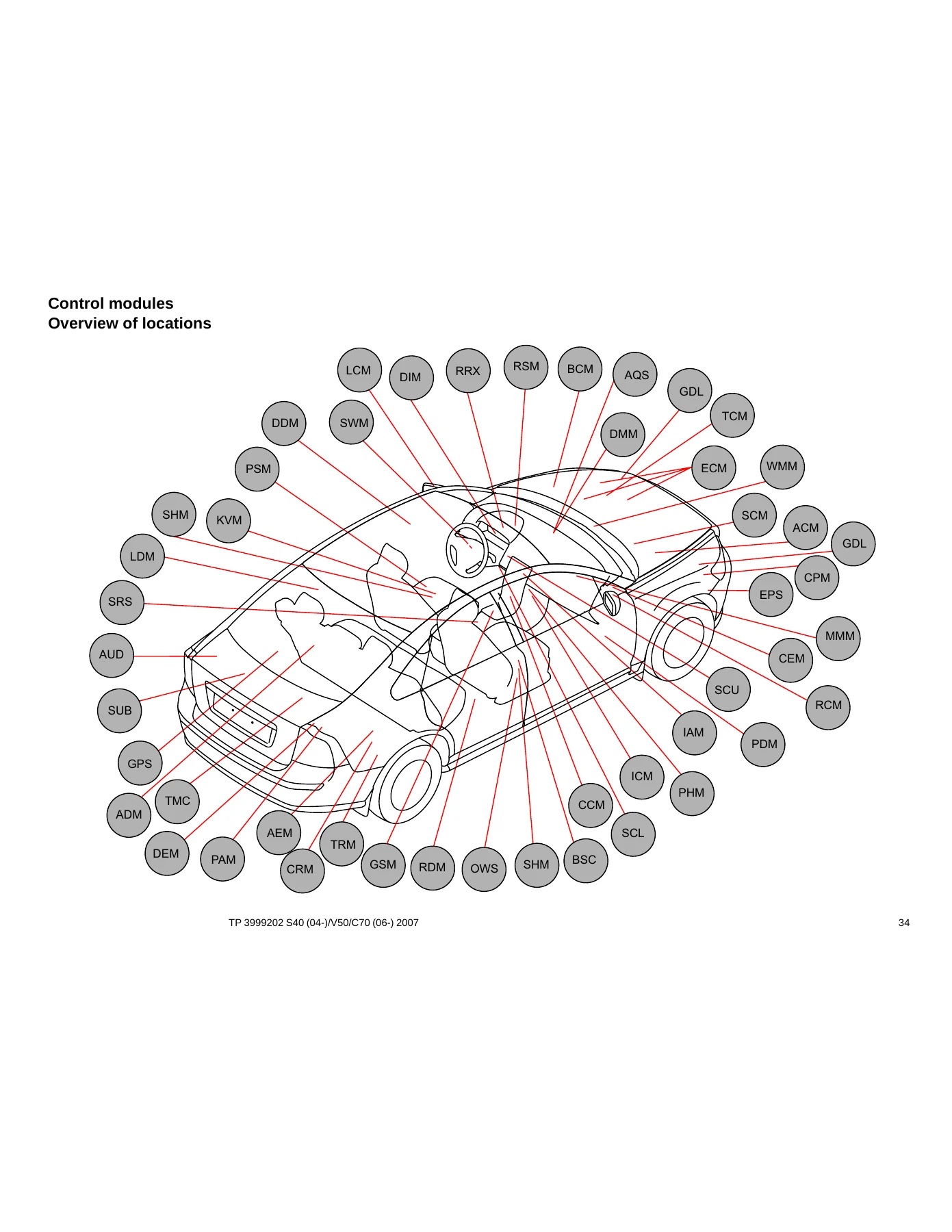
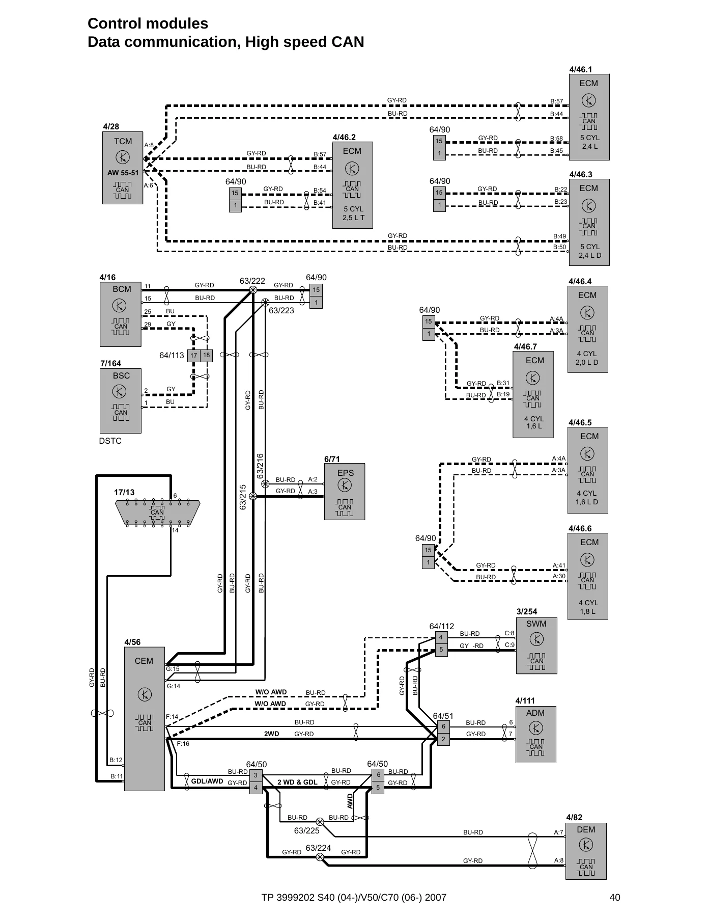
Networked systems receive dedicated treatment rather than being represented only as isolated circuits. The control-module section includes low-speed CAN, high-speed CAN, MOST layouts for S40/V50 and C70, and LIN communication. Module designations include the Central Electronic Module, Engine Control Module, Brake Control Module, Transmission Control Module, Climate Control Module, Driver Information Module, Electrical Power Steering Module, Keyless Vehicle Module, Parking Assistance Module, Supplemental Restraint System Module, door modules, seat modules, audio and multimedia modules and numerous other units shown within the manual.
Coverage and Applicability
The manual contains circuits for several engine and equipment configurations rather than one single powertrain. Engine-management sections shown in the contents include Diesel, 5-cyl. 2.4l; 4-cyl. 1.6l; 4-cyl. 1.8l & 2.0l; 5-cyl.; 5-cyl. Turbo; Diesel, 4-cyl. 1.6l; and Diesel, 4-cyl. 2.0l. Separate diagrams distinguish equipment and vehicle variations where required, including S40/V50 versus C70, LHD and RHD arrangements, Bi-Xenon lighting, gasoline and diesel systems, transmission variations and market-specific circuits.
An important publication note states that changes introduced up to April 2006 are included. Changes made to vehicles after that date are not included, and the manual directs the reader to service bulletins where necessary. It also notes that Volvo models were supplied in market-adapted versions, so some illustrations or text may not apply to every vehicle in every country. Matching the diagram to the vehicle’s actual equipment and configuration is therefore important when using TP 3999202 for diagnosis or repair work.
Chapters Covered
- Using the wiring diagrams
- Abbreviations, component designations, branching points, connectors, electrical distribution, data communication, symbols and component locations
- Electrical distribution, fuses and relays
- Engine compartment distribution box F1-F10, F11-F18, F20-F31, F32-F34 and F35-FH1
- Central Electronic Module fuses F43-F49, F51-F63, F64-F74 and F77-F86; battery PF1-PF2
- Ignition switch and relays, engine compartment R2-R14, CEM R15-R18, CEM R1-R11B and other relays
- Ground connections
- Ground overview and locations 31/3 through 31/117, including chassis ground connections
- Control modules and vehicle networks
- Module location/designation overviews, CEM, low-speed CAN, high-speed CAN, MOST S40/V50, MOST C70, LIN, SCU and AEM
- Group 23 – Fuel system
- Engine management for the listed 4-cylinder, 5-cylinder, turbo and diesel configurations
- Emission-control circuits for 1.6l, 1.8l & 2.0l, 5-cyl. and 5-cyl. Turbo configurations
- Groups 26 and 27 – Cooling and engine control
- Cooling fan, diesel cooling fan and cruise-control circuits for 4-cyl. and 5-cyl. configurations
- Groups 32 and 33 – Charging and starting
- Power supply for 4-cyl. and 5-cyl.; starting systems for 4-cyl., 5-cyl. and 5-cyl. Diesel
- Group 35 – Lighting
- Follow-me-home, high/low beam, Bi-Xenon, manual and automatic beam-length adjustment
- Position, parking and tail lights; fog, brake and reversing lights for S40/V50 and C70
- Interior lighting, instrument/control illumination and auxiliary lights
- Group 36 – Additional electrical equipment
- Direction indicators and hazard warning, windshield and headlight washer systems, V50 rear wiper/washer, rain sensor and horn
- Immobilizer/SCL, keyless vehicle systems, front/rear parking assistance and anti-theft alarm
- Accessory Electronic Module circuits
- Group 37 – Wiring and fuses
- 12V outlets, diagnostics system and 4-pin, 7-pin and 13-pin tow-hitch cable harnesses
- Groups 38 and 39 – Instruments and infotainment
- Driver Information Module and seat-belt reminder circuits
- Audio, High Performance/Premium Sound, cellular phone, satellite radio, multimedia, traffic information, navigation, handsfree systems and subwoofer
- Group 43 – Transmission
- Automatic transmission AW55-51, transmission M66 and Differential Electronic Module
- Groups 59 and 64 – Brakes and steering
- Brake control system with STC, brake control system with DSTC and electronic power steering
- Group 83 – Doors and openings
- Central locking, tailgate/storage locking, child safety lock, fuel-filler flap, remote-control receiver and power windows
- Power sunroof S40/V50 and power roof C70
- Groups 84 and 85 – Exterior and interior equipment
- Power/heated door mirrors, heated rear window and Blind Spot Information System
- Power seats, memory-seat configurations for LHD/RHD and heated seats
- Group 87 – Climate control
- PTC element, gasoline, 5-cyl. and Diesel 1.6l & 2.0l climate-control circuits
- Parking/auxiliary heater, electric engine-heater relay and Flexifuel engine heater
- Group 88 – Internal equipment
- Auto-dimming rearview mirror and SRS circuits for S40/V50 and C70
IMAGES PREVIEW

- Connector and harness reference
- Connectors, branching points and cable-harness routing for engine, engine compartment, dashboard, floor, roof, tunnel, doors, rear side panels and tailgates
- Component illustrations, index and list of components
The breadth of the 2007 Volvo S40 (04-), V50, C70 (06-) Wiring Diagram Manual – TP 3999202 means a technician can move from a system diagram to related fuse and relay information, ground locations, control-module connections, connector references and harness routing without relying on a single schematic in isolation. The later connector, branching-point and component-location material is particularly useful when a circuit has been identified electrically but the physical connection or harness route must then be located in the vehicle.
Useful for Electrical Diagnosis and Repair Planning
The diagrams cover both basic electrical loads and heavily networked systems. Power supply and starting circuits sit alongside engine management, cooling, lighting, wipers, keyless entry, parking assistance, alarms, audio, transmission electronics, brake control, steering, roof and door systems, power seats, climate control and restraint-system wiring. Fuse tables identify fuse functions and amperage values, relay sections show relay functions and positions, and ground sections associate numbered grounds with the components connected to them. Together, these references help narrow a fault from a symptom to the relevant power feed, module, fuse, relay, ground, connector or harness path.
Safety Information Included
The opening pages contain specific warnings for vehicles equipped with SRS, SIPS bag and IC systems. They stress extra caution around restraint-system components and wiring and state that work involving those systems, or other components that may affect them, must be performed in accordance with the appropriate Volvo service information. This safety material is part of the manual and should be reviewed before electrical work around restraint-system circuits.
Get the Wiring Information You Need
The 2007 Volvo S40 (04-), V50, C70 (06-) Wiring Diagram Manual – TP 3999202 gives you the circuit information needed to trace electrical faults, verify power and ground paths, identify fuses and relays, follow control-module communication, locate connectors and branching points, and understand how harnesses are routed through the covered vehicles. Using the correct diagram, component designation and electrical data can reduce guesswork when diagnosing wiring faults, checking a repair or planning electrical work. Your purchase is delivered as an instant PDF after payment with no physical shipping required; it can be viewed on compatible computers, tablets or phones and pages can be printed when a paper reference is more convenient at the vehicle.
Reviews
There are no reviews yet.