
2007 Yamaha FZ1-N FZ1-S FZ1-SA Service Manual – 5D0-28197-E0
Original price was: $34.95.$19.95Current price is: $19.95.
Complete 2007 Yamaha FZ1-N, FZ1-S and FZ1-SA service manual (document 5D0-28197-E0). Covers engine, chassis, ABS, fuel injection, EXUP, electrical systems and wiring diagrams for the 998cc inline-four FZ1 platform.
Description
2007 Yamaha FZ1-N, FZ1-S and FZ1-SA Service Manual — 5D0-28197-E0
This is the complete 2007 Yamaha FZ1-N FZ1-S FZ1-SA service manual, published under document number 5D0-28197-E0 (first edition, October 2006). It is the workshop reference for the 998cc liquid-cooled DOHC inline-four FZ1 platform, covering routine maintenance through full engine and chassis teardown for the FZ1-N(W), FZ1-S(W) and the ABS-equipped FZ1-SA.
Because the FZ1-SA adds an anti-lock brake system that the other two variants do not share, the manual dedicates dedicated ABS sections covering the hydraulic unit, wheel sensors and sensor rotors, the ABS ECU and motor relay, self-diagnosis, hydraulic unit operation tests and malfunction-code troubleshooting. The EXUP exhaust valve system, immobilizer circuit and the electronically controlled fuel injection system are all documented in the same level of detail.
File Details
- Manual type: Yamaha Service Manual
- Brand / publisher: Yamaha Motor Co., Ltd.
- Models covered: FZ1-N(W), FZ1-S(W), FZ1-SA (2007)
- Language: English
- Page count: 522 pages
- File format: PDF
- Document number: 5D0-28197-E0
- First edition: October 2006
Chapters Covered
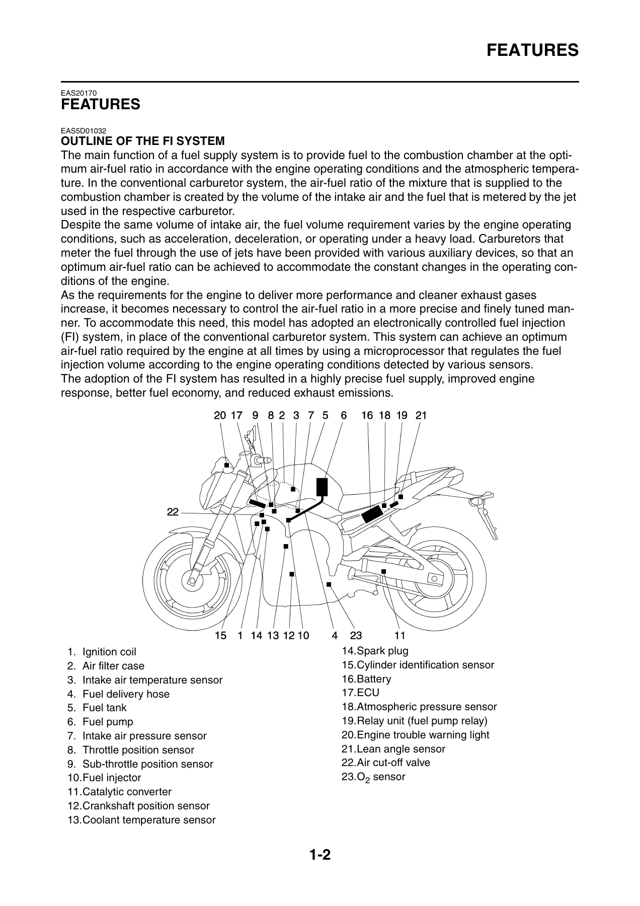
- General Information — Vehicle identification number and model label, FI system outline, ABS outline, ABS component functions, special tools
- Specifications — General dimensions and weight, engine specifications, chassis specifications, electrical specifications, general/engine/chassis tightening torques, lubrication points and lubricant types
- Periodic Maintenance — Maintenance chart, valve clearance, throttle body synchronization, exhaust gas volume (CO) adjustment, engine idling speed, throttle cable free play, spark plugs, compression pressure, engine oil level and change, engine oil pressure, clutch cable free play, air filter element, throttle body joints, fuel line, crankcase breather hose, exhaust system, EXUP cables, EXUP servo motor, coolant level and change, cooling system, brake fluid level, front and rear brake pads, brake hoses, rear brake light switch, bleeding the hydraulic brake system, shift pedal position, drive chain slack, drive chain lubrication, steering head, front fork, rear shock absorber, tires, wheels, cables, levers, pedals, sidestand, centerstand, rear suspension lubrication, headlight bulbs, headlight beam adjustment
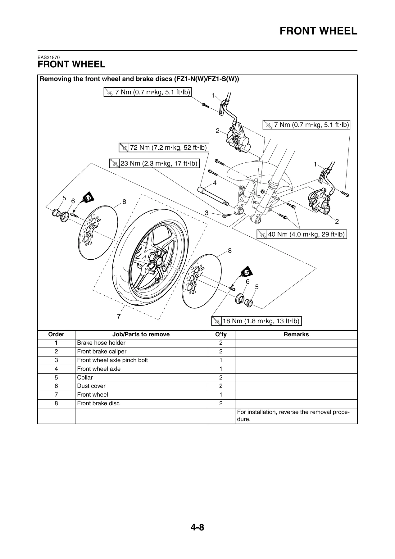
- Chassis — General chassis and cover removal, front wheel (removal, axle checks, wheel runout, wheel bearings, ABS sensor and sensor rotor, static balance, installation), rear wheel (removal, wheel check, drive hub, sprocket, ABS sensor and sensor rotor, static balance, installation), front brake (disc check, pad replacement, caliper disassembly, master cylinder removal/assembly), rear brake (disc check, pad replacement, caliper, master cylinder), ABS (hydraulic unit removal and installation, hydraulic unit operation test, trial run), handlebar, front fork (removal, disassembly, checking, assembly, installation), steering head, rear shock absorber assembly, swingarm, chain drive
- Engine — Engine removal and installation, drive sprocket, exhaust pipe and EXUP valve pipe, camshafts, cylinder head, valves and valve springs, generator, starter clutch, crankshaft position sensor, electric starter, clutch, shift shaft, oil pump, crankcase, crankshaft, transmission
- Cooling System — Radiator, oil cooler, thermostat, water pump
- Fuel System — Fuel tank, fuel pump, throttle bodies, injectors, throttle position sensor, sub-throttle position sensor, sub-throttle servo motor, thermo wax, air induction system
- Electrical System — Ignition system, electric starting system, starting circuit cut-off system, charging system, lighting system, signaling system, cooling system, fuel injection system, ECU self-diagnostic function, diagnostic mode, fuel pump system, immobilizer system, ABS (circuit diagram, components, connector locations, ABS ECU and ABS motor relay, troubleshooting outline, malfunction codes, deleting codes, final check), electrical components, switch checks, bulbs and bulb sockets, fuses, battery, relays, ignition coils, crankshaft position sensor, lean angle sensor, wheel sensor, starter motor, stator coil, rectifier/regulator, horn, fuel sender, speed sensor, radiator fan motor, coolant temperature sensor, throttle position sensor, sub-throttle position sensor, air induction system solenoid, atmospheric pressure sensor, cylinder identification sensor, intake air pressure sensor, intake air temperature sensor
- Troubleshooting — Starting failures, incorrect engine idling speed, poor medium-and-high-speed performance, faulty gear shifting, shift pedal does not move, jumps out of gear, faulty clutch, overheating, over cooling, poor braking performance, faulty front fork legs, unstable handling, faulty lighting or signaling system, troubleshooting at the ABS warning light
- Wiring Diagram — Full-color wiring diagrams for FZ1-N(W) 2007, FZ1-S(W) 2007 and FZ1-SA 2007, with color codes
Altogether the FZ1-N FZ1-S FZ1-SA service manual walks a technician through the complete lifecycle of the machine. The opening general-information chapter explains the fuel injection layout, the ABS layout and the special tools required before any work begins. The specifications chapter collects every torque value, clearance, capacity and service limit in one place, and the periodic maintenance chapter turns those numbers into a step-by-step service schedule with the correct order of operations. From there the chassis and engine chapters break each assembly down into removal, disassembly, inspection, reassembly and installation, with exploded diagrams, job instruction charts and tightening torques for every fastener.
What This FZ1 Service Manual Enables You to Do
With this manual on hand you can carry out the full range of jobs the FZ1 platform calls for. Routine work — oil and filter changes, coolant changes, valve clearance measurement and adjustment, throttle body synchronization, spark plug replacement, drive chain adjustment and lubrication, brake pad replacement, brake bleeding — is covered with the exact specifications Yamaha specifies. Deeper work is covered too: camshaft removal and timing chain service, cylinder head removal and valve seat lapping, clutch inspection and replacement, crankshaft and connecting rod clearance measurement with Plastigauge, transmission and shift fork inspection, oil pump rotor clearance checks, and full crankcase separation.
On the electronics side, the manual documents the ECU self-diagnostic function, the diagnostic mode used to activate the ignition coils, injectors, EXUP servo motor, sub-throttle servo motor, radiator fan relay and headlight relay one at a time, and the full fault-code table. The immobilizer system section explains how to register the code re-registering key and standard keys, how to void a lost standard key, and how to interpret the self-diagnosis error codes 51 through 56. On the FZ1-SA, the ABS section goes further — it walks through the ABS warning light diagnostics, the malfunction-code table, each code’s probable cause and the hydraulic unit operation test used to verify the system after service.
The value of having the correct Yamaha procedure rather than a generic guess is significant on a machine like the FZ1. Torque values on the cylinder head, connecting rod bolts and crankcase main journal bolts are specified with multi-stage tightening and a final angle, and the camshaft cap bolts must be loosened and tightened in a criss-cross pattern from the outside in. The EXUP cable adjustment, sub-throttle position sensor voltage and thermo wax adjustment all have specific setup steps that are easy to get wrong without the reference. The FZ1-SA hydraulic unit and brake hose routing is also safety-critical — the manual explicitly warns that reversing the front and rear brake hose connections will cause the brake lever and pedal to respond in the wrong order.
IMAGES PREVIEW
Instant PDF Delivery
This 2007 Yamaha FZ1-N FZ1-S FZ1-SA service manual is delivered as an instant-download PDF after checkout — no shipping, no waiting on a physical book. It opens on any device that reads PDFs (desktop, laptop, tablet or phone), and you can print the pages you need for the garage and keep the rest of the file clean. Because the whole file is 522 pages, it is worth keeping on a shop computer as a reference you can search through and flip between chapters while a job is in progress.

Reviews
There are no reviews yet.