2008 Allison TS3989 3000 & 4000 Product Families Troubleshooting Manual – PDF DOWNLOAD
Original price was: $74.95.$29.95Current price is: $29.95.
2008 Allison TS3989 3000 & 4000 Product Families Troubleshooting Manual – PDF DOWNLOAD
Description
2008 Allison TS3989 3000 & 4000 Product Families Troubleshooting Manual – PDF DOWNLOAD
DESCRIPTION:
2008 Allison TS3989 3000 & 4000 Product Families Troubleshooting Manual – PDF DOWNLOAD
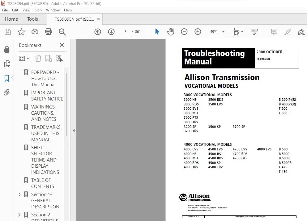
FOREWORD — How to Use This Manual :
This manual provides troubleshooting information for the 3000 and 4000 Product Families Transmissions. Service
Manuals SM4013EN and SM4014EN, plus Parts Catalogs PC2150EN and PC2456EN may be used in conjunction
with this manual.
This manual includes:
• Description of the 3000 and 4000 Product Families Allison 4TH Generation Electronic Control system.
• Description of the electronic control system components.
• Description of diagnostic codes, system responses to faults, and troubleshooting.
• Wire, terminal, and connector repair information.
Specific instructions for using many of the available or required service tools and equipment are not included in
this manual. The service tool manufacturer will furnish instructions for using the tools or equipment.
Additional information may be published from time to time in Service Information Letters (SIL) and will be
included in future revisions of this and other manuals. Please use these SILs to obtain up-to-date information
concerning Allison Transmission products.
This publication is revised periodically to include improvements, new models, special tools, and procedures. A
revision is indicated by a new date on the title page and in the lower left corner of the rear cover. Check with your
Allison Transmission service outlet for the currently applicable publication. Additional copies of this publication
may be purchased from authorized Allison Transmission service outlets. Look in your telephone directory under
the heading of Transmissions — Truck, Tractor, etc.
Take time to review the Table of Contents and the manual. Reviewing the Table of Contents will aid you in quickly
locating information.
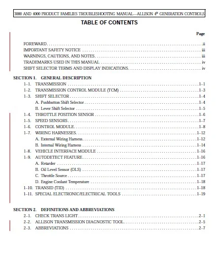
TABLE OF CONTENTS:
2008 Allison TS3989 3000 & 4000 Product Families Troubleshooting Manual – PDF DOWNLOAD
FOREWARD. . . . . . . . . . . . . . . . . . . . . . . . . . . . . . . . . . . . . . . . . . . . . . . . . . . . . . . . . . . . . . . . . . . . . . . . . . .ii
IMPORTANT SAFETY NOTICE . . . . . . . . . . . . . . . . . . . . . . . . . . . . . . . . . . . . . . . . . . . . . . . . . . . . . . . . . iii
WARNINGS, CAUTIONS, AND NOTES. . . . . . . . . . . . . . . . . . . . . . . . . . . . . . . . . . . . . . . . . . . . . . . . . . . iii
TRADEMARKS USED IN THIS MANUAL . . . . . . . . . . . . . . . . . . . . . . . . . . . . . . . . . . . . . . . . . . . . . . . . iv
SHIFT SELECTOR TERMS AND DISPLAY INDICATIONS. . . . . . . . . . . . . . . . . . . . . . . . . . . . . . . . . . . iv
SECTION 1. GENERAL DESCRIPTION
1–1. TRANSMISSION . . . . . . . . . . . . . . . . . . . . . . . . . . . . . . . . . . . . . . . . . . . . . . . . . . . . . . . . . . . . . . . 1–1
1–2. TRANSMISSION CONTROL MODULE (TCM) . . . . . . . . . . . . . . . . . . . . . . . . . . . . . . . . . . . . . . 1–3
1–3. SHIFT SELECTOR . . . . . . . . . . . . . . . . . . . . . . . . . . . . . . . . . . . . . . . . . . . . . . . . . . . . . . . . . . . . . . 1–4
A. Pushbutton Shift Selector . . . . . . . . . . . . . . . . . . . . . . . . . . . . . . . . . . . . . . . . . . . . . . . . . . . . . . . 1–4
B. Lever Shift Selector . . . . . . . . . . . . . . . . . . . . . . . . . . . . . . . . . . . . . . . . . . . . . . . . . . . . . . . . . . . 1–5
1–4. THROTTLE POSITION SENSOR . . . . . . . . . . . . . . . . . . . . . . . . . . . . . . . . . . . . . . . . . . . . . . . . . .1–6
1–5. SPEED SENSORS. . . . . . . . . . . . . . . . . . . . . . . . . . . . . . . . . . . . . . . . . . . . . . . . . . . . . . . . . . . . . . . 1–7
1–6. CONTROL MODULE. . . . . . . . . . . . . . . . . . . . . . . . . . . . . . . . . . . . . . . . . . . . . . . . . . . . . . . . . . . . 1–8
1–7. WIRING HARNESSES. . . . . . . . . . . . . . . . . . . . . . . . . . . . . . . . . . . . . . . . . . . . . . . . . . . . . . . . . .1–12
A. External Wiring Harness. . . . . . . . . . . . . . . . . . . . . . . . . . . . . . . . . . . . . . . . . . . . . . . . . . . . . . .1–12
B. Internal Wiring Harness . . . . . . . . . . . . . . . . . . . . . . . . . . . . . . . . . . . . . . . . . . . . . . . . . . . . . . .1–14
1–8. VEHICLE INTERFACE MODULE . . . . . . . . . . . . . . . . . . . . . . . . . . . . . . . . . . . . . . . . . . . . . . . .1–16
1–9. AUTODETECT FEATURE. . . . . . . . . . . . . . . . . . . . . . . . . . . . . . . . . . . . . . . . . . . . . . . . . . . . . . .1–16
A. Retarder . . . . . . . . . . . . . . . . . . . . . . . . . . . . . . . . . . . . . . . . . . . . . . . . . . . . . . . . . . . . . . . . . . .1–17
B. Oil Level Sensor (OLS) . . . . . . . . . . . . . . . . . . . . . . . . . . . . . . . . . . . . . . . . . . . . . . . . . . . . . . .1–17
C. Throttle Source . . . . . . . . . . . . . . . . . . . . . . . . . . . . . . . . . . . . . . . . . . . . . . . . . . . . . . . . . . . . . .1–17
D. Engine Coolant Temperature . . . . . . . . . . . . . . . . . . . . . . . . . . . . . . . . . . . . . . . . . . . . . . . . . . .1–18
1–10. TRANSID (TID) . . . . . . . . . . . . . . . . . . . . . . . . . . . . . . . . . . . . . . . . . . . . . . . . . . . . . . . . . . . . . . .1–18
1–11. SPECIAL ELECTRONIC/ELECTRICAL TOOLS . . . . . . . . . . . . . . . . . . . . . . . . . . . . . . . . . . . .1–19
SECTION 2. DEFINITIONS AND ABBREVIATIONS
2–1. CHECK TRANS LIGHT. . . . . . . . . . . . . . . . . . . . . . . . . . . . . . . . . . . . . . . . . . . . . . . . . . . . . . . . . . 2–1
2–2. ALLISON TRANSMISSION DIAGNOSTIC TOOL. . . . . . . . . . . . . . . . . . . . . . . . . . . . . . . . . . . . 2–5
2–3. ABBREVIATIONS . . . . . . . . . . . . . . . . . . . . . . . . . . . . . . . . . . . . . . . . . . . . . . . . . . . . . . . . . . . . . . 2–7
SECTION 3. BASIC KNOWLEDGE
3–1. BASIC KNOWLEDGE REQUIRED. . . . . . . . . . . . . . . . . . . . . . . . . . . . . . . . . . . . . . . . . . . . . . . . 3–1
3–2. USING THE TROUBLESHOOTING MANUAL. . . . . . . . . . . . . . . . . . . . . . . . . . . . . . . . . . . . . . 3–1
3–3. SYSTEM OVERVIEW . . . . . . . . . . . . . . . . . . . . . . . . . . . . . . . . . . . . . . . . . . . . . . . . . . . . . . . . . . 3–2
3–4. IMPORTANT INFORMATION IN THE TROUBLESHOOTING PROCESS. . . . . . . . . . . . . . . . 3–2
3–5. BEGINNING THE TROUBLESHOOTING PROCESS. . . . . . . . . . . . . . . . . . . . . . . . . . . . . . . . . 3–4
3–6. TCM DIAGNOSTIC PROCEDURE . . . . . . . . . . . . . . . . . . . . . . . . . . . . . . . . . . . . . . . . . . . . . . . . 3–5
3–7. RESTTING OF TCM PARAMETERS TO SUPPORT ENGINE UPDATE . . . . . . . . . . . . . . . . . . 3–6
3–8. RESETTING TCM AUTOSELECT . . . . . . . . . . . . . . . . . . . . . . . . . . . . . . . . . . . . . . . . . . . . . . . . 3–6
3–9. HYDRAULIC OPERATION DURING ELECTRICAL INTERRUPTION. . . . . . . . . . . . . . . . . . 3–6
SECTION 4. WIRE CHECK PROCEDURES
4–1. TESTING FOR OPENS, SHORTS BETWEEN WIRES, AND SHORTS-TO-GROUND. . . . . . . 4–1
4–2. TESTING AT TRANSMISSION FEEDTHROUGH CONNECTOR FOR INTERNAL
HARNESS OPENS, SHORTS BETWEEN WIRES, AND SHORTS-TO-GROUND . . . . . . . . . . 4–3
SECTION 5. FLUID CHECK PROCEDURES
5–1. OIL LEVEL SENSOR (OLS) INTRODUCTION. . . . . . . . . . . . . . . . . . . . . . . . . . . . . . . . . . . . . . 5–1
5–2. ELECTRONIC FLUID LEVEL READING (SHIFT SELECTOR) . . . . . . . . . . . . . . . . . . . . . . . . 5–3
A. Fluid Level Reading Procedure. . . . . . . . . . . . . . . . . . . . . . . . . . . . . . . . . . . . . . . . . . . . . . . . . . 5–3
5–3. ELECTRONIC FLUID LEVEL CHECK (ALLISON DOC™ FOR PC–SERVICE TOOL) . . . . . 5–5
A. Fluid Level Check Procedure . . . . . . . . . . . . . . . . . . . . . . . . . . . . . . . . . . . . . . . . . . . . . . . . . . . 5–5
5–4. COLD CHECK. . . . . . . . . . . . . . . . . . . . . . . . . . . . . . . . . . . . . . . . . . . . . . . . . . . . . . . . . . . . . . . . . 5–6
A. Purpose . . . . . . . . . . . . . . . . . . . . . . . . . . . . . . . . . . . . . . . . . . . . . . . . . . . . . . . . . . . . . . . . . . . . 5–6
B. Cold Check Procedure . . . . . . . . . . . . . . . . . . . . . . . . . . . . . . . . . . . . . . . . . . . . . . . . . . . . . . . . . 5–6
5–5 HOT CHECK . . . . . . . . . . . . . . . . . . . . . . . . . . . . . . . . . . . . . . . . . . . . . . . . . . . . . . . . . . . . . . . . . . 5–7
A. Hot Check Procedure. . . . . . . . . . . . . . . . . . . . . . . . . . . . . . . . . . . . . . . . . . . . . . . . . . . . . . . . . . 5–7
5–6 KEEPING FLUID CLEAN . . . . . . . . . . . . . . . . . . . . . . . . . . . . . . . . . . . . . . . . . . . . . . . . . . . . . . . 5–8
A. Foreign Material . . . . . . . . . . . . . . . . . . . . . . . . . . . . . . . . . . . . . . . . . . . . . . . . . . . . . . . . . . . . . 5–8
5–7 FLUID RECOMMENDATIONS . . . . . . . . . . . . . . . . . . . . . . . . . . . . . . . . . . . . . . . . . . . . . . . . . . . 5–8TABLE OF CONTENTS (cont’d)
SECTION 6.DIAGNOSTIC TROUBLE CODES (DTC)
6–1. DIAGNOSTIC CODE MEMORY. . . . . . . . . . . . . . . . . . . . . . . . . . . . . . . . . . . . . . . . . . . . . . . . . . . 6–1
6–2. CODE READING AND CODE CLEARING. . . . . . . . . . . . . . . . . . . . . . . . . . . . . . . . . . . . . . . . . . 6–2
6–3. DIAGNOSTIC CODE RESPONSE . . . . . . . . . . . . . . . . . . . . . . . . . . . . . . . . . . . . . . . . . . . . . . . . . 6–3
6–4. SHIFT SELECTOR DISPLAYS RELATED TO ACTIVE CODES . . . . . . . . . . . . . . . . . . . . . . . . 6–4
6–5. DIAGNOSTIC CODE LIST AND DESCRIPTION . . . . . . . . . . . . . . . . . . . . . . . . . . . . . . . . . . . . . 6–4
6–6. DIAGNOSTIC CODE TROUBLESHOOTING . . . . . . . . . . . . . . . . . . . . . . . . . . . . . . . . . . . . . . .6–14
A. Beginning the Troubleshooting Process . . . . . . . . . . . . . . . . . . . . . . . . . . . . . . . . . . . . . . . . . . .6–14
B. Solenoid Locations . . . . . . . . . . . . . . . . . . . . . . . . . . . . . . . . . . . . . . . . . . . . . . . . . . . . . . . . . . .6–14
C. Diagnostic Code Schematics . . . . . . . . . . . . . . . . . . . . . . . . . . . . . . . . . . . . . . . . . . . . . . . . . . .6–14
SECTION 7. INPUT AND OUTPUT FUNCTIONS
7–1. INPUT FUNCTIONS . . . . . . . . . . . . . . . . . . . . . . . . . . . . . . . . . . . . . . . . . . . . . . . . . . . . . . . . . . . . 7–1
7–2. OUTPUT FUNCTIONS . . . . . . . . . . . . . . . . . . . . . . . . . . . . . . . . . . . . . . . . . . . . . . . . . . . . . . . . . . 7–3
SECTION 8. GENERAL TROUBLESHOOTING OF PERFORMANCE COMPLAINTS
APPENDICES
A. IDENTIFICATION OF POTENTIAL CIRCUIT PROBLEMS . . . . . . . . . . . . . . . . . . . . . . . . . . . A–1
B. MEASURING CLUTCH AND RETARDER PRESSURES . . . . . . . . . . . . . . . . . . . . . . . . . . . . . B–1
C. SOLENOID AND CLUTCH CHART. . . . . . . . . . . . . . . . . . . . . . . . . . . . . . . . . . . . . . . . . . . . . . . C–1
D. WIRE/CONNECTOR CHART . . . . . . . . . . . . . . . . . . . . . . . . . . . . . . . . . . . . . . . . . . . . . . . . . . . . D–1
E. CONNECTOR PART NUMBERS, TERMINAL PART NUMBERS, . . . . . . . . . . . . . . . . . . . . . . .E–1
TOOL PART NUMBERS, AND REPAIR INSTRUCTIONS
F. THROTTLE POSITION SENSOR ADJUSTMENT . . . . . . . . . . . . . . . . . . . . . . . . . . . . . . . . . . . .F–1
G. WELDING ON VEHICLE/VEHICLE INTERFACE MODULE. . . . . . . . . . . . . . . . . . . . . . . . . . G–1
H. HYDRAULIC SCHEMATICS . . . . . . . . . . . . . . . . . . . . . . . . . . . . . . . . . . . . . . . . . . . . . . . . . . . . H–1
J. 3000 AND 4000 PRODUCT FAMILIES WIRING SCHEMATIC. . . . . . . . . . . . . . . . . . . . . . . . . . J–1
K. SOLENOID RESISTANCE CHARTS . . . . . . . . . . . . . . . . . . . . . . . . . . . . . . . . . . . . . . . . . . . . . . K–1
L. EXTERNALLY-GENERATED ELECTRONIC INTERFERENCE. . . . . . . . . . . . . . . . . . . . . . . . .L–1
M. DIAGNOSTIC TREE—3000 AND 4000 PRODUCT FAMILIES HYDRAULIC SYSTEM . . . . M–1
N. ALLISON DOC™ FOR PC–SERVICE TOOL. . . . . . . . . . . . . . . . . . . . . . . . . . . . . . . . . . . . . . . . N–1
P. INPUT/OUTPUT FUNCTIONS . . . . . . . . . . . . . . . . . . . . . . . . . . . . . . . . . . . . . . . . . . . . . . . . . . . .P–1
Q. THERMISTOR TROUBLESHOOTING INFORMATION . . . . . . . . . . . . . . . . . . . . . . . . . . . . . . Q–1
R. SAE J1939 COMMUNICATION LINK . . . . . . . . . . . . . . . . . . . . . . . . . . . . . . . . . . . . . . . . . . . . . R–1
IMAGES PREVIEW OF THE MANUAL:
2008 ALLISON TS3989 3000 & 4000 PRODUCT FAMILIES TROUBLESHOOTING MANUAL – PDF DOWNLOAD:
PLEASE NOTE:
- This is the SAME manual used by the dealers to troubleshoot any faults in your vehicle. This can be yours in 2 minutes after the payment is made.
- Contact us at [email protected] should you have any queries before your purchase or that you need any other service / repair / parts operators manual.
S.V