Trusted Business
Verified & Licensed
Virus Free Files
100% Safe Downloads
Secure Payment
SSL Protected
Instant Delivery
Available Immediately
Sale!


2008 Harley Davidson VRSC Models Electrical Diagnostics Manual – PDF DOWNLOAD 
2008 Harley Davidson VRSC Models Electrical Diagnostics Manual – PDF DOWNLOAD
2008 Harley Davidson VRSC Models Electrical Diagnostics Manual – PDF DOWNLOAD
Original price was: $98.95.$19.95Current price is: $19.95.
2008 Harley Davidson VRSC Models Electrical Diagnostics Manual – PDF DOWNLOAD
Instant PDF Download
Available immediately
Save to Your Device
Download & keep forever
Antivirus Scanned
100% virus-free
Trusted Worldwide
175,000+ customers
Description
2008 Harley Davidson VRSC Models Electrical Diagnostics Manual – PDF DOWNLOAD
IMAGES PREVIEW OF THE MANUAL:


DESCRIPTION:
2008 Harley Davidson VRSC Models Electrical Diagnostics Manual – PDF DOWNLOAD
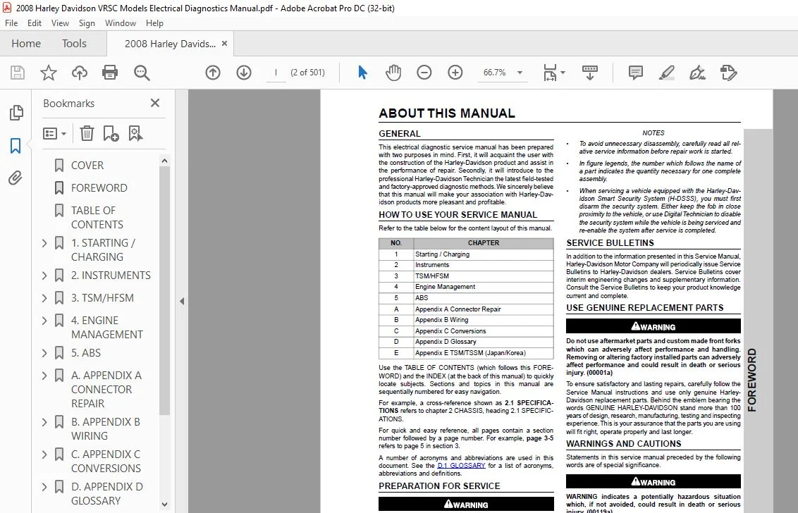
ABOUT THIS MANUAL
GENERAL:
- This electrical diagnostic service manual has been prepared with two purposes in mind. First, it will acquaint the user with the construction of the Harley-Davidson product and assist in the performance of repair.
- Secondly, it will introduce to the professional Harley-Davidson Technician the latest field-tested and factory-approved diagnostic methods.We sincerely believe that this manual will make your association with Harley-Davidson products more pleasant and profitable.
HOW TO USE YOUR SERVICE MANUAL :
Refer to the table below for the content layout of this manual.
NO. CHAPTER
1 Starting / Charging
2 Instruments
3 TSM/HFSM
4 Engine Management
5 ABS
A Appendix A Connector Repair
B Appendix B Wiring
C Appendix C Conversions
D Appendix D Glossary
E Appendix E TSM/TSSM (Japan/Korea)
- Use the TABLE OF CONTENTS (which follows this FOREWORD) and the INDEX (at the back of this manual) to quickly locate subjects. Sections and topics in this manual are sequentially numbered for easy navigation.
- For example, a cross-reference shown as 2.1 SPECIFICATIONS refers to chapter 2 CHASSIS, heading 2.1 SPECIFICATIONS.
- For quick and easy reference, all pages contain a section number followed by a page number. For example, page 3-5 refers to page 5 in section 3.
- A number of acronyms and abbreviations are used in this document. See the D.1 GLOSSARY for a list of acronyms, abbreviations and definitions.
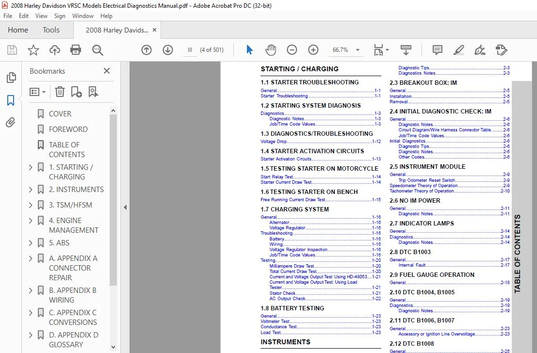
TABLE OF CONTENTS:
2008 Harley Davidson VRSC Models Electrical Diagnostics Manual – PDF DOWNLOAD
COVER................................................................................................  1
FOREWORD.............................................................................................  2
TABLE OF CONTENTS....................................................................................  4
1. STARTING / CHARGING............................................................................... 14
	1.1 STARTER TROUBLESHOOTING...................................................................... 16
		General...................................................................................... 16
		Starter Troubleshooting...................................................................... 16
	1.2 STARTING SYSTEM DIAGNOSIS.................................................................... 18
		Diagnostics.................................................................................. 18
	1.3 DIAGNOSTICS/TROUBLESHOOTING.................................................................. 27
		Voltage Drop................................................................................. 27
	1.4 STARTER ACTIVATION CIRCUITS.................................................................. 28
		Starter Activation Circuits.................................................................. 28
	1.5 TESTING STARTER ON MOTORCYCLE................................................................ 29
		Start Relay Test............................................................................. 29
		Starter Current Draw Test.................................................................... 29
	1.6 TESTING STARTER ON BENCH..................................................................... 30
		Free Running Current Draw Test............................................................... 30
	1.7 CHARGING SYSTEM.............................................................................. 31
		General...................................................................................... 31
		Troubleshooting.............................................................................. 31
		Testing...................................................................................... 35
	1.8 BATTERY TESTING.............................................................................. 38
		General...................................................................................... 38
		Voltmeter Test............................................................................... 38
		Conductance Test............................................................................. 38
		Load Test.................................................................................... 38
2. INSTRUMENTS....................................................................................... 40
	2.1 CHECKING FOR TROUBLE CODES................................................................... 42
		Check Engine Lamp............................................................................ 42
		Code Types................................................................................... 43
		Security Lamp................................................................................ 43
		Retrieving Trouble Codes..................................................................... 43
		Multiple Trouble Codes....................................................................... 43
	2.2 INSTRUMENT MODULE (IM) SELF DIAGNOSTICS...................................................... 44
		General...................................................................................... 44
		Diagnostics.................................................................................. 44
	2.3 BREAKOUT BOX: IM............................................................................. 46
		General...................................................................................... 46
		Installation................................................................................. 46
		Removal...................................................................................... 46
	2.4 INITIAL DIAGNOSTIC CHECK: IM................................................................. 47
		General...................................................................................... 47
		Initial Diagnostics.......................................................................... 47
	2.5 INSTRUMENT MODULE............................................................................ 50
		General...................................................................................... 50
		Speedometer Theory of Operation.............................................................. 50
		Tachometer Theory of Operation............................................................... 51
	2.6 NO IM POWER.................................................................................. 52
		General...................................................................................... 52
	2.7 INDICATOR LAMPS.............................................................................. 55
		General...................................................................................... 55
		Diagnostics.................................................................................. 55
	2.8 DTC B1003.................................................................................... 58
		General...................................................................................... 58
	2.9 FUEL GAUGE OPERATION......................................................................... 59
		General...................................................................................... 59
	2.10 DTC B1004, B1005............................................................................ 60
		General...................................................................................... 60
		Diagnostics.................................................................................. 60
	2.11 DTC B1006, B1007............................................................................ 64
		General...................................................................................... 64
	2.12 DTC B1008................................................................................... 66
		General...................................................................................... 66
	2.13 DTC U1016................................................................................... 68
		General...................................................................................... 68
		Diagnostics.................................................................................. 68
	2.14 DTC U1064................................................................................... 71
		General...................................................................................... 71
		Diagnostics.................................................................................. 71
	2.15 DTC U1300, U1301 OR BUS ER.................................................................. 74
		Diagnostics.................................................................................. 74
3. TSM/HFSM.......................................................................................... 76
	3.1 TURN SIGNAL OVERVIEW......................................................................... 78
		General...................................................................................... 78
		Security System: Japan/Korea................................................................. 78
		Turn Signal Functions........................................................................ 78
		Manual Cancellation.......................................................................... 78
		Automatic Cancellation....................................................................... 78
		Bank Angle Functions......................................................................... 78
		Bank Angle Restart........................................................................... 78
		Clutch/Neutral Interlock..................................................................... 78
		Security System H-DSSS....................................................................... 78
	3.2 HARLEY-DAVIDSON SMART SECURITY SYSTEM........................................................ 79
		Components................................................................................... 79
		Security Immobilization...................................................................... 79
		HFSM Features................................................................................ 80
	3.3 H-DSSS ACTUATION............................................................................. 82
		General...................................................................................... 82
		Sidecar Configuration........................................................................ 82
		Actuation.................................................................................... 82
		Fob Assignment............................................................................... 82
		Power Disruption and Configuring............................................................. 82
	3.4 PERSONAL IDENTIFICATION NUMBER (PIN)......................................................... 83
		General...................................................................................... 83
		Initial Pin Entry............................................................................ 83
		Changing the Pin............................................................................. 83
	3.5 ARMING/DISARMING SECURITY SYSTEM............................................................. 85
		Hands-Free Fob............................................................................... 85
		Security Lamp (Key Icon)..................................................................... 85
		Arming....................................................................................... 85
		Disarming.................................................................................... 86
	3.6 WARNINGS AND ALARMS.......................................................................... 87
		Warnings..................................................................................... 87
		Alarm........................................................................................ 87
		Siren Chirp Mode (Confirmation).............................................................. 87
	3.7 SERVICE/EMERGENCY FUNCTIONS.................................................................. 88
		Transport Mode............................................................................... 88
		Service Mode................................................................................. 88
		Four-Way Flashing............................................................................ 88
	3.8 TROUBLESHOOTING.............................................................................. 89
		Turn Signals (TSM/HFSM)...................................................................... 89
		Security System (HFSM)....................................................................... 89
		Diagnostics Mode............................................................................. 89
		Troubleshooting.............................................................................. 89
	3.9 CHECKING FOR DIAGNOSTIC TROUBLE CODES........................................................ 90
		General...................................................................................... 90
		Security Lamp Diagnostics.................................................................... 90
		Code Types................................................................................... 91
		Retrieving DTCs.............................................................................. 91
		Multiple DTCs/Priority Order................................................................. 92
	3.10 INITIAL DIAGNOSTIC CHECK.................................................................... 93
		General...................................................................................... 93
		Initial Diagnostics.......................................................................... 93
	3.11 INSTRUMENT MODULE (IM) SELF DIAGNOSTICS..................................................... 96
		General...................................................................................... 96
		Diagnostics.................................................................................. 96
	3.12 BREAKOUT BOX: TSM/HFSM...................................................................... 98
		General...................................................................................... 98
		Installation................................................................................. 98
		Removal...................................................................................... 98
	3.13 FAILS TO DISARM (HFSM ONLY).................................................................100
		General......................................................................................100
		Job/Time Codes...............................................................................100
		Diagnostics..................................................................................100
	3.14 DTC B0563...................................................................................103
		General......................................................................................103
		Diagnostics..................................................................................103
	3.15 TSM/HFSM: TURN SIGNAL ERRORS AND DTCS.......................................................104
		General......................................................................................104
		Diagnostics..................................................................................105
	3.16 DTC B1131, B1132 (HFSM ONLY)................................................................118
		General......................................................................................118
		Diagnostics..................................................................................118
	3.17 DTC B1134 STARTER OUTPUT HIGH...............................................................121
		General......................................................................................121
		Diagnostics..................................................................................121
	3.18 DTC B1135...................................................................................124
		Diagnostics..................................................................................124
	3.19 DTC B1136, B1142 (HFSM ONLY)................................................................125
		Diagnostics..................................................................................125
	3.20 DTC B1141 (HFSM ONLY).......................................................................126
		Diagnostics..................................................................................126
	3.21 DTC B1143, B1144, B1145 (HFSM ONLY).........................................................131
		General......................................................................................131
		Diagnostics..................................................................................131
	3.22 DTC B1154, B1155............................................................................136
		Diagnostics..................................................................................136
	3.23 DTC U1016, U1255............................................................................140
		General......................................................................................140
		Diagnostics..................................................................................140
	3.24 DTC U1300, U1301 OR BUS ER..................................................................143
		Diagnostics..................................................................................143
	3.25 TSM/HFSM: PASSWORD LEARN....................................................................144
		General......................................................................................144
		Password Learning............................................................................144
	3.26 HFSM MAINTENANCE............................................................................145
		General......................................................................................145
		Hands-Free Fob...............................................................................145
		Siren (If Installed).........................................................................145
4. ENGINE MANAGEMENT.................................................................................148
	4.1 SPECIFICATIONS...............................................................................150
		Specifications...............................................................................150
	4.2 EFI SYSTEM...................................................................................151
		General......................................................................................151
		Troubleshooting..............................................................................151
	4.3 DIAGNOSTIC INTRODUCTION......................................................................153
		System Problems..............................................................................153
		Resolving Problems...........................................................................153
	4.4 CHECKING FOR TROUBLE CODES...................................................................154
		Check Engine Lamp............................................................................154
		Code Types...................................................................................155
		Retrieving Diagnostic Trouble Codes..........................................................155
		Multiple Diagnostic Trouble Codes............................................................155
	4.5 INSTRUMENT MODULE (IM) SELF DIAGNOSTICS......................................................156
		General......................................................................................156
		Diagnostics..................................................................................156
	4.6 BREAKOUT BOX: ECM............................................................................158
		General......................................................................................158
		Installation.................................................................................158
		Removal......................................................................................158
	4.7 WIGGLE TEST..................................................................................159
		General......................................................................................159
		Procedure....................................................................................159
	4.8 INITIAL DIAGNOSTIC CHECK.....................................................................160
		General......................................................................................160
		Initial Diagnostics..........................................................................160
	4.9 ENGINE CRANKS, BUT WILL NOT START............................................................169
		General......................................................................................169
		Diagnostics..................................................................................169
	4.10 NO ECM POWER................................................................................177
		General......................................................................................177
		Diagnostics..................................................................................177
	4.11 STARTS, THEN STALLS.........................................................................182
		General......................................................................................182
		Diagnostics..................................................................................182
	4.12 FUEL SYSTEM ELECTRICAL TEST.................................................................186
		General......................................................................................186
		Diagnostics..................................................................................186
	4.13 SYSTEM RELAY FAULT..........................................................................192
		General......................................................................................192
		Diagnostics..................................................................................192
	4.14 FAN OPERATION CHECK.........................................................................197
		General......................................................................................197
		Diagnostics..................................................................................197
	4.15 FUEL PRESSURE TEST..........................................................................201
		General......................................................................................201
		Testing......................................................................................201
		Diagnostics..................................................................................202
	4.16 IDLE AIR CONTROL............................................................................204
		General......................................................................................204
		Diagnostics..................................................................................204
	4.17 MISFIRE AT IDLE OR UNDER LOAD...............................................................209
		General......................................................................................209
		Diagnostics..................................................................................209
	4.18 COMBUSTION ABSENT/INTERMITTENT..............................................................215
		General......................................................................................215
		Diagnostics..................................................................................215
	4.19 DTC P0107, P0108............................................................................219
		General......................................................................................219
		Diagnostics..................................................................................219
	4.20 DTC P0112, P0113............................................................................223
		General......................................................................................223
		Diagnostics..................................................................................223
	4.21 DTC P0117, P0118............................................................................227
		General......................................................................................227
		Diagnostics..................................................................................227
	4.22 DTC P0122, P0123............................................................................231
		General......................................................................................231
		Diagnostics..................................................................................231
	4.23 DTC P0131, P0132, P0134, P0151, P0152, P0154................................................235
		General......................................................................................235
		Diagnostics..................................................................................235
	4.24 DTC P0261, P0262, P0263, P0264..............................................................240
		General......................................................................................240
		Diagnostics..................................................................................240
	4.25 DTC P0373, P0374............................................................................245
		General......................................................................................245
		Diagnostics..................................................................................245
	4.26 DTC P0444, P0445............................................................................248
		General......................................................................................248
		Diagnostics..................................................................................248
	4.27 DTC P0501, P0502............................................................................253
		General......................................................................................253
		Diagnostics..................................................................................253
	4.28 DTC P0562, P0563............................................................................257
		General......................................................................................257
		Diagnostics..................................................................................257
	4.29 DTC P0603, P0605............................................................................261
		General......................................................................................261
		Diagnostics..................................................................................261
	4.30 DTC P1009, P1010............................................................................262
		General......................................................................................262
		Diagnostics..................................................................................262
	4.31 DTC P1351, P1352, P1354, P1355..............................................................265
		General......................................................................................265
		Diagnostics..................................................................................265
	4.32 DTC P1501, P1502............................................................................269
		General......................................................................................269
		Diagnostics..................................................................................269
	4.33 DTC U1064, U1255............................................................................274
		General......................................................................................274
		Diagnostics..................................................................................274
	4.34 DTC U1096, U1255............................................................................277
		General......................................................................................277
		Diagnostics..................................................................................277
5. ABS...............................................................................................280
	5.1 ANTILOCK BRAKE SYSTEM (ABS) GENERAL INFORMATION..............................................282
		Antilock Brake System (ABS) Description......................................................282
		Code Types...................................................................................284
		Retrieving Diagnostic Trouble Codes..........................................................284
		Multiple Trouble Codes.......................................................................284
	5.2 INSTRUMENT MODULE (IM) SELF DIAGNOSTICS......................................................285
		General......................................................................................285
		Diagnostics..................................................................................285
	5.3 BREAKOUT BOX: ABS............................................................................287
		General......................................................................................287
		Installation.................................................................................287
		Removal......................................................................................287
	5.4 INITIAL DIAGNOSTIC CHECK: ABS................................................................288
		General......................................................................................288
		Initial Diagnostics..........................................................................288
	5.5 ABS INDICATOR DIAGNOSTICS....................................................................292
		ABS Indicator Always On Or Inoperative.......................................................292
	5.6 DTC C0562....................................................................................296
		DTC C0562: Device Voltage Low................................................................296
	5.7 DTC C0563....................................................................................299
		DTC C0563: Device Voltage High...............................................................299
	5.8 DTC C1017....................................................................................302
		DTC C1017: Pump Motor Power Circuit Open Fault...............................................302
	5.9 DTC C1018....................................................................................305
		DTC C1018: Pump Motor Ground High Resistance Fault...........................................305
	5.10 DTC C1021, C1023............................................................................308
		DTC C1021, C1023: Wheel Speed Sensor Equals Zero (Front or Rear).............................308
	5.11 DTC C1025, C1027, C1206, C1208..............................................................311
		DTC C1025, C1027, C1206, C1208: Wheel Speed Signal Intermittent or Frequency Out Of Range....311
	5.12 DTC C1032, C1034............................................................................314
		DTC C1032, C1034: Wheel Speed Sensor Circuit Open Or Shorted (Front or Rear).................314
	5.13 DTC C1042...................................................................................320
		DTC C1042: Pump Motor Open...................................................................320
	5.14 DTC C1043...................................................................................321
		DTC C1043: Pump Motor Stalled................................................................321
	5.15 DTC C1094...................................................................................322
		DTC C1094: Front Brake Switch Always On......................................................322
	5.16 DTC C1095...................................................................................325
		DTC C1095: Front Brake Switch Open...........................................................325
	5.17 DTC C1151...................................................................................328
		DTC C1151: Front Wheel Release Too Long......................................................328
	5.18 DTC C1153...................................................................................331
		DTC C1153: Rear Wheel Release Too Long.......................................................331
	5.19 DTC C1158...................................................................................334
		DTC C1158: Calibration Programming Required..................................................334
	5.20 DTC C1212...................................................................................338
		DTC C1212: Front or Rear Brake Not Applied with Decel........................................338
	5.21 DTC C1214...................................................................................341
		DTC C1214: Rear Brake Switch Always On.......................................................341
	5.22 DTC C1216...................................................................................344
		DTC C1216: Rear Brake Switch Open............................................................344
	5.23 DTC C1014, C1055-C1066, C1118, C1121........................................................347
		DTC C1014, C1055-C1066, C1118, C1121: ECU Internal Fault.....................................347
	5.24 DTC U1300, U1301 OR BUS ER..................................................................351
		Diagnostics..................................................................................351
A. APPENDIX A CONNECTOR REPAIR.......................................................................352
	A.1 AMP 1-PLACE CONNECTORS.......................................................................354
		AMP 1-Place Connector Repair.................................................................354
	A.2 AMP MULTILOCK CONNECTORS.....................................................................356
		AMP Multilock Connector Repair...............................................................356
	A.3 DELPHI CONNECTORS............................................................................361
		Delphi Connector Repair......................................................................361
	A.4 DEUTSCH 1-PLACE ELECTRICAL CONNECTORS........................................................363
		Deutsch 1-Place Connector Repair.............................................................363
	A.5 DEUSCH ELECTRICAL CONNECTORS.................................................................364
		Deutsch Connector Repair.....................................................................364
	A.6 DEUTSCH STANDARD TERMINALS...................................................................368
		Deutsch Standard Terminal Crimps.............................................................368
	A.7 DEUTSCH MINI-TERMINAL CRIMPS.................................................................369
		Deutsch Mini Terminal Crimps.................................................................369
	A.8 DEUTSCH SOLID BARREL TERMINALS...............................................................370
		Deutsch Solid Barrel Terminal Crimps.........................................................370
	A.9 RELAY AND FUSE BLOCKS........................................................................372
		Fuse Block Repair............................................................................372
	A.10 150 METRI-PACK CONNECTORS...................................................................373
		150 Metri-Pack Connector Repair..............................................................373
	A.11 280 METRI-PACK CONNECTORS...................................................................375
		280 Metri-Pack Connector Repair..............................................................375
	A.12 480 METRI-PACK CONNECTORS...................................................................377
		480 Metri-Pack Connector Repair..............................................................377
	A.13 630 METRI-PACK CONNECTORS...................................................................378
		630 Metri-Pack Connector Repair..............................................................378
	A.14 800 METRI-PACK CONNECTORS...................................................................379
		Delphi Maxi-Fuse Housing Repair..............................................................379
	A.15 METRI-PACK TERMINALS........................................................................381
		Metri-Pack Terminal Crimps...................................................................381
	A.16 MOLEX CONNECTORS............................................................................383
		Molex Connector Repair.......................................................................383
	A.17 PACKARD ECM CONNECTOR.......................................................................385
		Packard 100W Connector Repair................................................................385
	A.18 PACKARD MICRO-64 CONNECTORS.................................................................387
		Packard Micro-64 Connector Repair............................................................387
	A.19 SEALED SPLICE CONNECTORS....................................................................390
		Sealed Splice Connector Repair...............................................................390
B. APPENDIX B WIRING.................................................................................392
	B.1 CONNECTORS...................................................................................394
		Connector Locations..........................................................................394
	B.2 WIRING DIAGRAMS..............................................................................396
		Wiring Diagram Information...................................................................396
		2008 VRSC Wiring Diagrams....................................................................397
C. APPENDIX C CONVERSIONS............................................................................422
	C.1 METRIC CONVERSION............................................................................424
		Conversion Table.............................................................................424
	C.2 FLUID CONVERSIONS............................................................................425
		United States System.........................................................................425
		Metric System................................................................................425
		British Imperial System......................................................................425
	C.3 TORQUE CONVERSIONS...........................................................................426
		United States System.........................................................................426
		Metric System................................................................................426
D. APPENDIX D GLOSSARY...............................................................................428
	D.1 GLOSSARY.....................................................................................430
		Acronyms and Abbreviations...................................................................430
E. APPENDIX E TSM/TSSM (JAPAN/KOREA).................................................................432
	E.1 TSM/TSSM (JAPAN/KOREA) OVERVIEW..............................................................434
		General......................................................................................434
		Troubleshooting..............................................................................434
	E.2 TSM/TSSM FEATURES............................................................................436
		General......................................................................................436
		Turn Signal Functions........................................................................436
		Bank Angle Function..........................................................................436
		Clutch/Neutral Interlock Functions...........................................................436
		Security Alarm and Immobilization Functions..................................................436
	E.3 TSM/TSSM VEHICLE DELIVERY....................................................................438
		General......................................................................................438
		Configuring A TSSM...........................................................................438
		Power Disruption and Configuring.............................................................438
		Key FOB Assignment: TSSM.....................................................................438
		Pin Entry: TSSM..............................................................................439
		Changing the Pin: TSSM.......................................................................441
	E.4 TSM/TSSM TURN SIGNAL FUNCTIONS...............................................................442
		General......................................................................................442
		Automatic Cancellation.......................................................................442
		Manual Cancellation..........................................................................442
		Four-Way Flashing............................................................................442
		Diagnostics Mode.............................................................................442
	E.5 TSM/TSSM BANK ANGLE FUNCTION.................................................................443
		General......................................................................................443
		Operation....................................................................................443
	E.6 SECURITY SYSTEM FUNCTIONS: TSSM..............................................................444
		General......................................................................................444
		Alarm Sensitivity: TSSM......................................................................444
		Auto-Arming Function: TSSM...................................................................445
		Storage Mode: TSSM...........................................................................446
	E.7 ARMING/DISARMING: TSSM.......................................................................447
		General......................................................................................447
		Security Lamp................................................................................447
		Using Key FOB: TSSM..........................................................................447
		Using the Pin................................................................................447
	E.8 DIAGNOSTIC TROUBLE CODES (DTC)...............................................................449
		TSM/TSSM.....................................................................................449
		Code Types...................................................................................450
		Retrieving Diagnostic Trouble Codes..........................................................450
		Multiple Diagnostic Trouble Codes............................................................451
	E.9 INITIAL DIAGNOSTIC CHECK: TSM/TSSM...........................................................452
		General......................................................................................452
		Initial Diagnostics..........................................................................452
	E.10 INSTRUMENT MODULE (IM) SELF DIAGNOSTICS.....................................................455
		General......................................................................................455
		Diagnostics..................................................................................455
	E.11 BREAKOUT BOX: TSM/TSSM......................................................................457
		General......................................................................................457
		Installation.................................................................................457
		Removal......................................................................................457
	E.12 FAILS TO DISARM.............................................................................458
		General......................................................................................458
		Diagnostics..................................................................................458
	E.13 TURN SIGNAL ERRORS: B1121, B1122, B1141.....................................................461
		General......................................................................................461
		Diagnostics..................................................................................461
	E.14 DTC B0563...................................................................................472
		General......................................................................................472
		Diagnostics..................................................................................472
	E.15 DTC B1131, B1132............................................................................473
		General......................................................................................473
		Diagnostics..................................................................................473
	E.16 DTC B1134...................................................................................476
		General......................................................................................476
		Diagnostics..................................................................................476
	E.17 DTC B1135...................................................................................479
		General......................................................................................479
	E.18 DTC B1154, B1155............................................................................480
		General......................................................................................480
		Diagnostic Notes.............................................................................480
	E.19 DTC U1016...................................................................................483
		General......................................................................................483
		Diagnostics..................................................................................483
	E.20 DTC U1300, U1301 OR BUS ER..................................................................486
		General......................................................................................486
		Diagnostics..................................................................................486
	E.21 PASSWORD LEARN..............................................................................487
		General......................................................................................487
		Password Learning............................................................................487
	E.22 TSSM MAINTENANCE............................................................................488
		General......................................................................................488
		Key FOB......................................................................................488
		Siren (If Installed).........................................................................488
TOOLS................................................................................................490
TORQUE VALUES........................................................................................494
INDEX................................................................................................496
2008 HARLEY DAVIDSON VRSC MODELS ELECTRICAL DIAGNOSTICS MANUAL – PDF DOWNLOAD:
PLEASE NOTE:
- This is not a physical manual but a digital manual – meaning no physical copy will be couriered to you. The manual can be yours in the next 2 mins as once you make the payment, you will be directed to the download page IMMEDIATELY.
- This is the same manual used by the dealers inorder to diagnose your vehicle of its faults.
- Require some other service manual or have any queries: please WRITE to us at [email protected]
S.V