
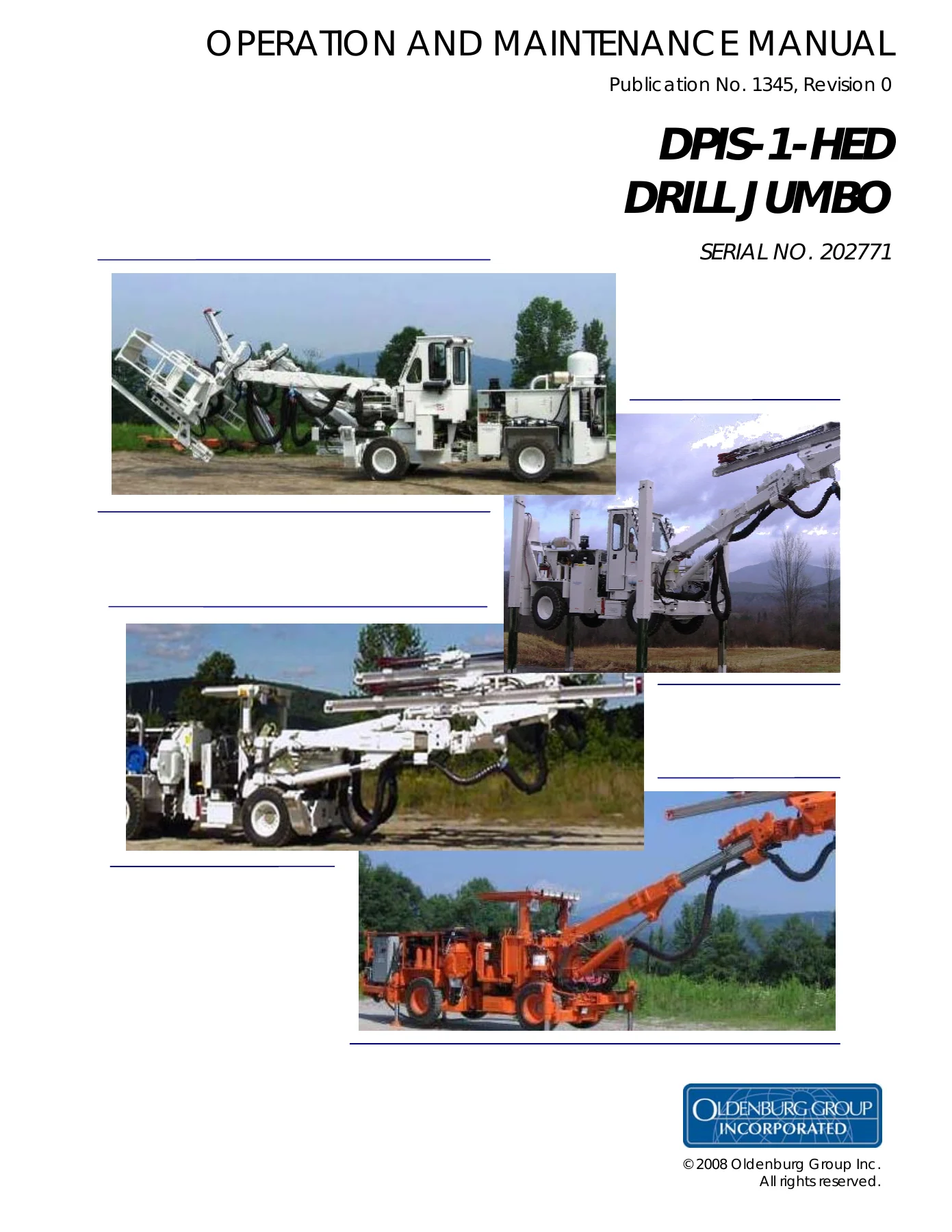
2008 Oldenburg DPIS-1-HED Drill Jumbo Operation & Maintenance Manual – Serial 202771
Original price was: $39.95.$24.95Current price is: $24.95.
Operation and maintenance manual for the Oldenburg DPIS-1-HED Drill Jumbo, machine serial 202771. Publication No. 1345, Revision 0. Covers safe operation, pre-operation inspection, starting and tramming, drilling procedures, maintenance schedules, lubrication, feed and hydraulic adjustments, hydraulic drill control troubleshooting, component-failure procedures, and hydraulic/electrical schematics.
Description
2008 Oldenburg DPIS-1-HED Drill Jumbo Operation & Maintenance Manual – Serial 202771
This 2008 Oldenburg DPIS-1-HED Drill Jumbo Operation & Maintenance Manual – Serial 202771 provides operating, inspection, maintenance, adjustment, troubleshooting, and system-reference information for the DPIS-1-HED drill jumbo identified as unit serial number 202771. Publication No. 1345, Revision 0, combines day-to-day operator procedures with detailed maintenance information for the chassis, boom, feed, drill, hydraulic controls, lubrication points, brake system, and supporting machine systems.
The manual goes well beyond basic machine operation. It explains how to prepare the jumbo for work, carry out pre-operation checks, start and warm the machine, perform a brake test while tramming, set up for drilling, inspect drill lubrication, collar and drill holes, clean holes, and shut the machine down. The maintenance section then develops into scheduled service checklists, lubrication charts, inspection criteria, dimensional clearances, hydraulic adjustments, pressure and flow specifications, troubleshooting charts, and failure-response procedures.
File Details
- Manual type: Operation and Maintenance Manual
- Brand: Oldenburg Group Incorporated
- Model: DPIS-1-HED Drill Jumbo
- Machine serial number: 202771
- Publication number: 1345
- Revision: 0
- Year: 2008
- Language: English
- Page count: 131 pages
- File format: PDF
Machine and Component Identification
The manual includes a component serial-number section specific to unit 202771. It identifies major installed equipment including a Mercedes OM 904 LA diesel engine, John Deere front and rear axles, Dana 302 / 338 transfer gearbox, Sauer Danfoss tram pump and tram motor, Parker engine-driven hydraulic pump, Indiana Heat Transfer radiator, Monarch hydraulic electric fill motor, and Sullair EM006 air compressor. The recommended filter list further identifies the machine as a DPIS-1-HED with a Mercedes 904 Tier III engine.
An appendix lists additional equipment references for the Mercedes 904 Tier III engine, diesel engine controller, John Deere pump drive and drive axles, Dana/Spicer drop box, Sauer Danfoss Series 51 tram motor and Series 90 tram pump, Helac actuator, Sullair 40 CFM air compressor, fire suppression system, grease pump, angle indicator, CH 38 drill, and dual caliper brake.
Chapters Covered
- Safety
- Safe operation, protective equipment, emergency preparation, fuel and fluid safety, rotating driveline hazards, hot parts, high-pressure fluids, lifting, chemicals, wheel chocking and drill-operation precautions
- General Information
- Component serial numbers
- Customer survey
- Part-number information
- Glossary of terms
IMAGES PREVIEW


- Operation
- Pre-operation inspection
- Starting the engine
- Tramming with brake test
- Set-up for drilling
- Drill lubrication inspection
- Drilling procedures
- Post-operation procedures
- Maintenance
- Torque values
- Recommended filters
- Recommended fluids
- Maintenance schedule
- Drill, chassis, boom and feed lubrication charts
- Feed guide clearance inspection
- Feed guide wear inspection
- Drill steel inspection
- Feed assembly alignment inspection
- Feed assembly travel inspection
- Hydraulic cylinder leak test
- Dual caliper brake adjustment
- Hydraulic cable feed adjustments
- Hydraulic drill control adjustments
- Gauge pressures and functional flow tables
- Hydraulic drill control troubleshooting guide
- Hydraulic component failure procedures
- Schematics and Diagrams
- Boom circuit
- Drill circuit
- Jack and steering circuit
- Air and water circuit
- Tram circuit
- Hammer, rotation and feed circuit
- Brake system
- AC electrical schematic
- DC controls schematic
- DPIS-HED wiring block diagram
- Appendix
- Equipment and related part-number references
Together, these sections make the Oldenburg DPIS-1-HED operation and maintenance manual useful for both operators and maintenance personnel. Routine machine preparation and drilling instructions are tied directly to scheduled maintenance, inspection standards, adjustment procedures, hydraulic operating data, and troubleshooting information so that operating symptoms can be followed into the relevant service procedures.
Drilling Operation and Control Information
The operation section gives detailed sequences rather than only control descriptions. It includes switch and control positions for startup, warm-up instructions, tramming precautions, brake testing, electric-powered drilling setup, drill lubrication inspection, hole location, starting the drill, collaring, full drilling, automatic retract operation, hole cleaning, and post-operation shutdown.
Useful operating figures are printed directly in the procedures. Drill lubrication is checked using 35-45 psi lubricating air pressure, with hydraulic oil pressure set 20-40 psi above the air pressure. The manual specifies a metering-valve opening of 6-8 turns for the lubrication check. During drilling, collaring feed pressure is described in the 300-500 psi range, while full drilling feed thrust is shown in the 900-1500 psi range in the operating procedure. The manual also explains inspection for flushing-head seal leakage and the consequences of water entering the drill percussor assembly.
Scheduled Maintenance and Lubrication
The DPIS-1-HED maintenance program is organized into repeatable inspection intervals. Checklists cover every-shift, daily, 40-hour and 250-hour maintenance, while lubrication charts add service points and longer intervals where applicable. Tasks include checking instruments, lights, tires, wheel lugs, fuel, hydraulic oil, filters, hoses, cylinders, engine and compressor oil, feed cables, centralizer bushings, park brake, drive lines, steering, belts and drill components.
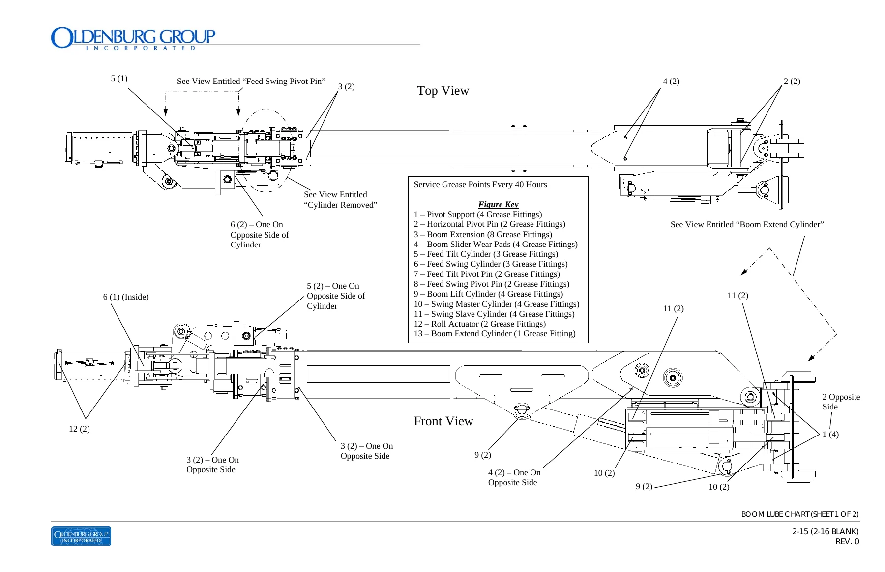
Dedicated lube charts identify service points on the drill, chassis, boom and feed. These drawings show grease fitting locations and service intervals for components such as stabilizer pins, axle bearings, drive shafts, articulation pivots, steering-cylinder pins, boom pivots and cylinders, feed swing and tilt points, hose-wheel assembly, midpoint centralizer and auxiliary swing assembly. The manual also provides recommended fluids for the axles, hydraulic system, driveline, engine coolant, diesel fuel, engine oil, compressor oil and grease, plus a complete filter-change list for serial 202771.
Inspection, Adjustment and Repair Reference
A substantial portion of the 2008 Oldenburg DPIS-1-HED Drill Jumbo Operation & Maintenance Manual – Serial 202771 is devoted to measurements and adjustments that directly affect drilling performance. Feed-guide inspection procedures specify minimum clearances for the hose-wheel assembly, drill cradle, midpoint centralizer and lower gibs. Feed assembly travel checks address front-centralizer clearance, drill-cradle travel, bit position and retract operation.
The adjustment section covers feed-guide clearance, feed assembly alignment, gib-to-feed-guide clearance and feed travel. It also provides a dual caliper brake adjustment procedure with lining-to-disc running clearances and tightening values. Hydraulic drill-control adjustment procedures cover hammer main reliefs, feed speed, hammer collar adjustment, hammer shift, feed relief, feed thrust, rotation torque control sequence, collar adjustment, retract pressure and rotation relief/speed settings.
For example, the hydraulic control procedures specify 3200 PSI for the P1 and P2 main relief adjustment, 2500 PSI for feed relief pressure, 2000 PSI for the P3 rotation relief, and separate feed-thrust ranges for CH38 and CH32 drill configurations. A dedicated CH-38 operating-pressure table provides rotation, hammer, air and water values, including 18 GPM rotation flow, 30 GPM hammer flow, 125 PSI drilling air pressure and 150 PSI water pressure.
Hydraulic Troubleshooting and Component Failure Procedures
The hydraulic drill controls troubleshooting section provides pressure and functional-flow tables followed by extensive problem/probable-cause/solution charts. Diagnostic topics include a completely inoperative system, slow or erratic operation, dirty or milky oil, foaming oil, overheating, hammer starting and drilling problems, low or fluctuating hammer pressure, collaring difficulties, feed relief and feed thrust problems, inability to set feed speed, feed failure, slow retract, automatic retract faults, rotation problems, slow boom movement, cylinder leakage, relief-valve faults, valve shifting problems and pump failures.
The component-failure section explains contamination-control procedures after hose, hammer, rotation-unit, pump, hydraulic cooler and air-lubrication failures. It includes flushing procedures before connecting replacement components and directs replacement of return and high-pressure filters after a major component failure, followed by another filter change after 40 hours of operation.
Hydraulic and Electrical Schematics
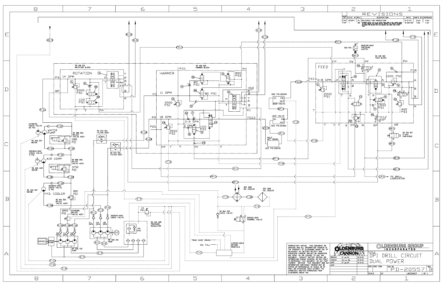
The final technical section includes hydraulic reference drawings for the boom, drill, jack and steering, air and water, tram, hammer/rotation/feed and brake circuits, together with AC electrical, DC control and wiring diagrams. The manual notes that some hydraulic schematics apply to multiple machine models and may show small configuration differences, while retaining the intended circuit relationships and system function. Component lists accompanying schematics are intended to identify the components represented, while correct component part numbers are to be checked against the applicable parts manual.
Keep the DPIS-1-HED Operating and Maintained to the Published Procedures
The 2008 Oldenburg DPIS-1-HED Drill Jumbo Operation & Maintenance Manual – Serial 202771 gives operators and technicians a single reference for operating the jumbo, checking it before work, performing scheduled maintenance, lubricating major assemblies, measuring feed-system clearances, adjusting brake and hydraulic controls, diagnosing drilling-system faults, responding correctly to component failures, and tracing hydraulic or electrical circuits. Following the documented procedures, pressures, clearances, lubrication points and inspection intervals helps avoid adjustment by guesswork and supports consistent servicing of this specific machine configuration.
Delivered as an instant PDF after payment with no physical shipping required. Open it on a computer, tablet or phone, keep it available at the machine or workshop, and print the pages you need for inspection, adjustment, maintenance or troubleshooting work.
Reviews
There are no reviews yet.