
2011 Polaris Ranger RZR 800 Service Manual – RZR S, RZR 4 & EPS Repair Guide PDF
Original price was: $29.95.$17.95Current price is: $17.95.
Complete 2011 Polaris Ranger RZR 800 service manual covering the RZR, RZR EPS, RZR S, RZR S EPS INT’L, RZR 4 and RZR 4 EPS. Engine, EFI, clutching, transmission, final drive, brakes, steering, suspension and electrical procedures in one downloadable PDF.
Description
2011 Polaris Ranger RZR 800 Service Manual – What This PDF Delivers
This is the full workshop service manual for the 2011 Polaris Ranger RZR 800 family, written for the technician who actually has to pull the engine, split the transmission case, set TPS voltage, service a Hilliard front gearcase, re-shim a rear axle spool or chase an intermittent AWD fault. The 2011 Polaris Ranger RZR 800 Service Manual covers the two-seat RZR and RZR EPS, the wide-track RZR S and RZR S EPS INT’L, and the four-seat RZR 4 and RZR 4 EPS. All six variants share the 760cc H.O. twin-cylinder liquid-cooled engine, designated 1204276 RZR800HO-11, but the manual separates each model’s dimensions, weight, suspension travel, tire sizes, battery spec and clutch chart so you are not reading RZR 4 data when you are working on an RZR S.
File Details
- Manual type: Polaris service / repair manual
- Brand: Polaris
- Model year: 2011
- Models covered: RANGER RZR 800, RANGER RZR 800 EPS, RANGER RZR S, RANGER RZR S EPS INT’L, RANGER RZR 4, RANGER RZR 4 EPS
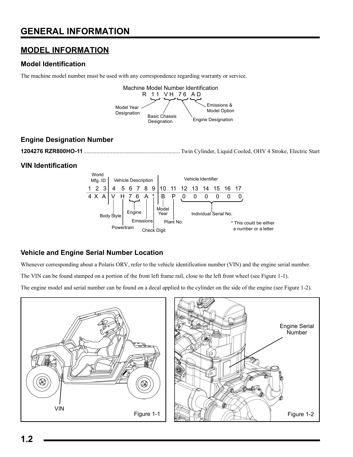
- Engine designation: 1204276 RZR800HO-11 – Twin Cylinder, Liquid Cooled, OHV 4 Stroke, Electric Start
- Language: English
- Page count: 406 pages
- File format: PDF
Chapters Covered in the 2011 Polaris Ranger RZR 800 Service Manual
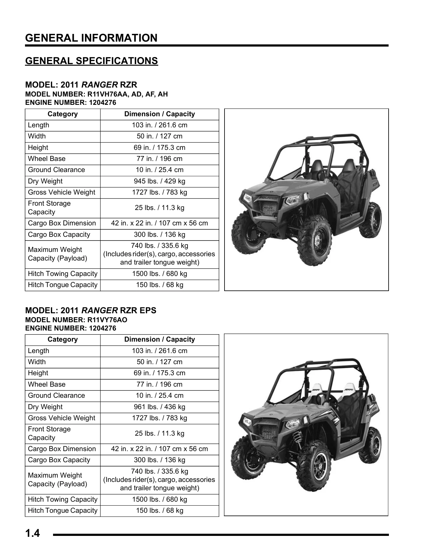
- Chapter 1 – General Information: model identification, engine designation number, VIN identification, vehicle and engine serial number location, publication numbers, replacement keys, special tools, general specifications for each model, conversion table, standard torque specifications, SAE and metric tap/drill sizes, decimal equivalents, glossary of terms
- Chapter 2 – Periodic Maintenance: break-in period, maintenance chart key, pre-ride and 25 hour interval, 50-500 hour interval, maintenance quick reference, grease lubrication points, lubricants and service products, shift cable inspection and adjustment, fuel system and air intake, vent lines, throttle pedal inspection and freeplay adjustment, air filter service, engine oil level and oil/filter service, engine breather hose, engine and transmission mounts, compression and leakdown test, exhaust spark arrestor, transmission and gearcase lubrication, front and rear gearcase lubrication, cooling system level, strength, pressure test and hose inspection, radiator removal, wheel and hub torque table, wheel removal and installation, tire inspection and pressure, drive shaft boot inspection, battery maintenance and charging, spark plug service, engine-to-frame ground, steering inspection and freeplay, tie rod end and wheel hub inspection, wheel toe alignment inspection and adjustment, spring preload adjustment, FOX and Walker Evans shock adjustments, brake fluid, pad and disc inspection, brake hose inspection, maintenance log
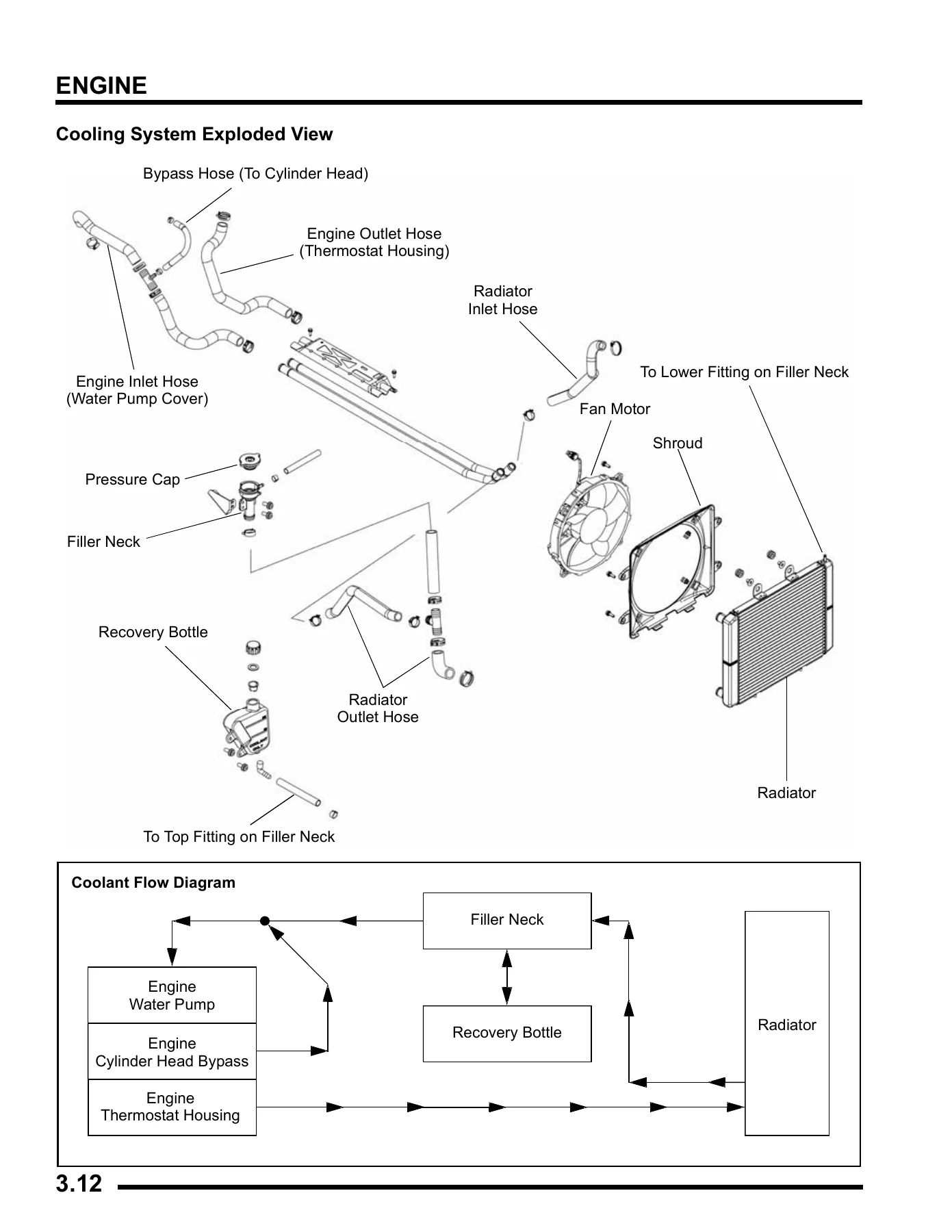
- Chapter 3 – Engine: engine specifications, crankcase, oil pump/gears/engine cover, stator cover/starter/water pump/lubrication system, cylinder/cylinder head/piston, engine EFI sensors/valve cover/general components, engine torque specifications, 800 EFI engine service specifications, special tools, cooling system specifications and pressure test, cooling system exploded view and bleeding procedure, engine lubrication specifications, accessible engine components, oil pressure test, oil flow chart, engine removal, engine/transmission separation, engine disassembly and inspection, cylinder head assembly exploded view, rocker arms and push rods, cylinder head removal and inspection, valve seal/spring service, valve inspection, valve seat reconditioning, cylinder head reassembly, valve sealing test, cylinder removal, valve lifter removal and inspection, piston removal and inspection, cylinder inspection, cylinder hone selection and honing procedure, piston-to-cylinder clearance, piston ring installed gap, starter drive bendix removal and inspection, flywheel/stator removal and inspection, engine crankcase disassembly and inspection, camshaft inspection, engine reassembly, crankcase reassembly, flywheel/stator installation, oil pump priming, engine installation, engine break-in period, troubleshooting
- Chapter 4 – Electronic Fuel Injection: general information, special tools, EFI system exploded view, EFI system component locations, fuel tank, quick connect fuel lines, electronic fuel injection operation overview, initial priming and starting procedure, electronic control unit (ECU), ECU service and replacement, T-MAP sensor test and replacement, crankshaft position sensor (CPS) test and replacement, fuel injectors service/test/replacement, fuel pump, fuel sender test, fuel pump test and replacement, fuel tank removal and installation, idle air control (IAC) test and replacement, throttle position sensor (TPS) resistance tests and replacement, camshaft phase sensor test and replacement, engine coolant temperature sensor (ECT) test and replacement, ignition coil and HT lead tests, EFI diagnostics, instrument cluster trouble code display, EFI troubleshooting, Digital Wrench operation, diagnostic connector, software versions and updates, ECU reprogramming (reflash), EFI system electrical operation
- Chapter 5 – Body / Steering / Suspension: torque specifications, special tools, cab frame assembly and removal, body exploded views, side safety nets, dash instruments and controls, hood and front body work, front and rear bumpers, seat assembly, seat belts and mounting, floor and rocker panels, rear cargo box and fenders, chassis and main frame, body component removal, steering assembly exploded view, steering wheel and steering shaft removal, steering shaft bearing replacement, electronic power steering assembly, upper and lower steering shaft removal and installation, power steering unit removal and installation, front A-arms removal and replacement, ball joint service, front stabilizer bar, rear A-arms removal, rear stabilizer bar, shocks and springs, FOX shock exploded views and rebuild, Walker Evans shock exploded view and rebuild
- Chapter 6 – Clutching: special tools and supplies, torque specifications, PVT system overview, general operation, drive clutch operation, driven clutch operation, PVT break-in, maintenance and inspection, overheating diagnosis, PVT system service, PVT covers and ducting components, PVT disassembly and assembly, clutch offset procedure, drive belt removal/inspection/installation, drive clutch service, spring specifications, shift weights, drive clutch exploded view, clutch disassembly, spider removal, roller/pin/thrust washer inspection, button to tower clearance inspection, shift weight inspection, bearing inspection, moveable sheave bushing inspection, bushing service, clutch assembly, driven clutch service and exploded view, driven clutch disassembly and assembly, troubleshooting
- Chapter 7 – Final Drive: special tools, torque specifications, front bearing carrier inspection and removal, bearing replacement and carrier installation, front drive shaft removal, drive shaft and CV joint handling tips, outer CV joint/boot replacement, inner plunging joint/boot replacement, drive shaft installation, propshaft service, propshaft removal and installation, support bearing replacement, propshaft U-joint service, front gearcase/centralized Hilliard exploded view, all wheel drive operation, AWD diagnosis, gearcase removal/disassembly/inspection/assembly/installation, rear bearing carrier, rear drive shaft, rear gearcase removal/disassembly/assembly/installation, rear gearcase exploded view, RZR S INT’L rear gearcase with differential lock/unlock, differential disassembly and assembly, wheel hubs front and rear exploded views
- Chapter 8 – Transmission: torque values and specifications, shift lever removal and installation, shift cable inspection and adjustment, transmission service notes, transfer case disassembly and reassembly, transmission shift housing disassembly and reassembly, troubleshooting, transmission exploded view
- Chapter 9 – Brakes: general specifications, torque specifications, special tools, brake system service notes, brake noise troubleshooting, hydraulic brake system operation, brake system exploded views for RZR/RZR S/RZR S INT’L and RZR 4, master cylinder removal and installation, brake pedal lever, brake bleeding and fluid change, front brake pads, pad inspection/assembly/installation, brake burnishing procedure, front caliper service and exploded views, caliper removal/disassembly/inspection/assembly/installation, front brake disc runout, disc inspection and replacement, rear brake pads, rear caliper service, rear caliper exploded view, rear caliper removal/disassembly/inspection/assembly/installation, rear brake disc inspection and replacement, troubleshooting
- Chapter 10 – Electrical: general information, special tools, electrical service notes, under-dash components, switches and controls, brake light switch, headlamp switch, ignition key switch (domestic and INT’L), AWD/2WD switch, AWD/2WD/TURF switch, turn signal switch, hazard switch, transmission gear position switch, vehicle speed sensor, rear diff solenoid (INT’L), instrument cluster, rider information display, information display area, diagnostic mode, instrument cluster pinouts, instrument cluster removal and installation, all wheel drive coil, headlights and adjustment, headlamp bulb and housing, tail/brake lights, cooling system break-out diagram, fan control circuit operation and testing, coolant temperature sensor, EFI diagnostics, fuel sender, fuse box fuses/relays/circuit breaker, fuse box detail, relay operation, charging system, current draw key off, charging system break-even test, alternator tests, regulator/rectifier, charging system testing flow chart, battery service, battery specifications, battery removal/installation/off season storage, battery testing, OCV open circuit voltage test, load test, battery conductance analyzer, charging procedure, starting system, troubleshooting, voltage drop test, starter motor removal/disassembly, brush inspection and replacement, armature testing, starter reassembly/installation, starter drive, starter solenoid bench test, starter solenoid operation, starter exploded view, starting system testing flow chart, electronic power steering (EPS), EPS operation, EPS 8-way wire harness connector, EPS system breakout, EPS troubleshooting with MIL on and off, EPS troubleshooting using Digital Wrench, electrical system breakouts, AWD, vehicle speed sensor, cooling fan, charging system, chassis power, key-on battery power, electronic power steering, engine start (starter interlock)
What This Polaris RZR 800 Manual Actually Lets You Do
The value here is not the page count – it is that every number in the book was written for these exact machines. The engine chapter carries the 800 EFI service specifications you cannot safely guess at: cam lobe height for intake and exhaust, camshaft journal outer diameters and bore inner diameters for MAG, center and PTO, camshaft oil clearance and end play, cylinder head warp limit, valve guide inner diameter and protrusion, valve stem diameters and oil clearances, valve spring free length, cylinder bore, taper and out-of-round limits, piston-to-cylinder clearance, piston ring installed gaps and ring-to-groove clearances, connecting rod big-end side and radial clearance, crankshaft runout limit. Cylinders are nicasil-lined and the manual is blunt about that – it tells you to hone only enough to deglaze and warns that a common spring-loaded glaze breaker is not advised.
IMAGES PREVIEW
Torque sequences are where people get into trouble and this manual does not hand-wave them. Cylinder head bolts are a four-stage procedure: torque to 15 +/- 1.5 ft. lbs. in sequence, back off all head bolts 5 turns in sequence, torque to 35 +/- 4 ft. lbs. in sequence, then tighten all head bolts another 90 degrees (1/4 turn) in sequence. Crankcase bolts, gear/stator housing bolts, water pump housing bolts, oil pump bolts and rocker cover bolts all carry their own sequences and values. The manual also flags the fasteners that must not be reused – the locking agent is destroyed on removal, and the text says so plainly for A-arm hardware, brake caliper mounting bolts, brake disc mounting bolts and the circlips in the drive shafts.
If you own or service a 2011 RZR 800, there are jobs in this book that are genuinely hard to do correctly without it. Setting TPS voltage to .700 +/- .050 Vdc with the TPS tester or Digital Wrench sensor data display. Bleeding the cooling system at the cylinder head bleed screw and torquing it to 70 +/- 10 in. lbs. Checking drive clutch belt-to-sheave clearance and adding or removing .030″ or .060″ offset washers behind the driven clutch until the belt rests evenly between the drive clutch sheaves. Priming the oil pump with the Oil Priming Adapter PU-45778 and a three-quarter full filter before the first start-up after a rebuild, because the manual states that failing to do this may cause internal engine damage. Rebuilding FOX Podium X or 2.0 Piggyback shocks with the correct IFP depth – 2.40 in. front, 3.40 in. rear – and charging to 200 psi nitrogen, not air. Those are the details that separate a machine that runs for years from one that comes back on a trailer.
The 2011 Polaris Ranger RZR 800 Service Manual also handles the diagnostic side. The instrument cluster diagnostic mode is documented with the SPN and FMI breakout, and the Diagnostic Trouble Code table lists the fault, the suspect parameter number, the failure mode identifier and the matching Digital Wrench P-code across TPS, T-MAP, ECT, IAT, system power, gear sensor, ECU memory, crankshaft position sensor, camshaft phase sensor, both injectors, rear differential output, fan relay, ignition coil drivers, fuel pump driver, ECU output supply voltages, AWD control circuit, EPS faults and all four IAC stepper pins. AWD that will not engage gets its own diagnosis path with the 21.6 – 26.4 Ohm coil resistance spec and the two-distinct-wear-bands check on the armature plate.
Who This 2011 Polaris RZR 800 Repair Guide Is For
Independent shops that see RZR 800s and want the same procedures the dealer tech uses. Owners doing their own top-end, clutch, brake or gearcase work and who would rather torque to spec than guess. Anyone chasing an electrical fault who needs the actual pinout, resistance value or voltage drop limit instead of a forum thread. And anyone rebuilding a machine that has been sitting – the cooling system bleed, oil pump priming and break-in oil change procedure at 25 hours or one month are all laid out so a fresh rebuild is not ruined in the first hour.
Instant PDF Delivery
Your copy of the 2011 Polaris Ranger RZR 800 Service Manual downloads immediately after checkout – no shipping, no waiting, no physical book to lose in the shop. The PDF opens on a laptop, tablet or phone, so you can keep the engine chapter open on the bench and the torque table open on your phone at the same time. Print just the pages for the job you are on and take them into the garage where they belong. Search the file to jump straight to a specification instead of flipping through hundreds of pages.
Reviews
There are no reviews yet.