
2012 2013 Suzuki DF15A DF20A 4-Stroke Outboard Repair Manual
Original price was: $34.95.$19.95Current price is: $19.95.
Complete 306-page Suzuki DF15A / DF20A 4-stroke outboard repair manual for 2012-2013, covering the DF15A, DF15AE, DF20A and DF20AE models. Instant PDF download with full service, maintenance and diagnostic procedures.
Description
2012 2013 Suzuki DF15A DF20A 4-Stroke Outboard Repair Manual
This Suzuki DF15A DF20A 4-stroke outboard repair manual is the complete workshop reference for the 2012 and 2013 model years. It covers the Suzuki DF15A, DF15AE, DF20A and DF20AE outboard motors — the 15 PS and 20 PS lean-burn four-stroke twins built by Thai Suzuki Motor Co. Whether you are a marine technician, a dealer mechanic or an owner who does their own maintenance, this manual gives you the same procedures, tightening torques, service limits and diagnostic logic used to keep these engines running correctly.
At 306 pages, the manual is structured the way Suzuki trained its service network: general information and scheduled maintenance first, then the power head, mid unit, lower unit and finally the wire and hose routing diagrams. Every system is covered with removal, disassembly, inspection, reassembly and installation steps, supported by photographs, line drawings, exploded views and circuit diagrams.
File Details
- Manual type: Service / repair workshop manual
- Brand: Suzuki
- Models covered: DF15A, DF15AE, DF20A, DF20AE
- Language: English
- Page count: 306
- File format: PDF
- Manual number: 99500-89L00-01E
- Publication date: June 2012
- Prepared by: Marine Design Department, Suzuki
Chapters Covered
- Section 00 — Precautions: General precautions and replacement parts notice
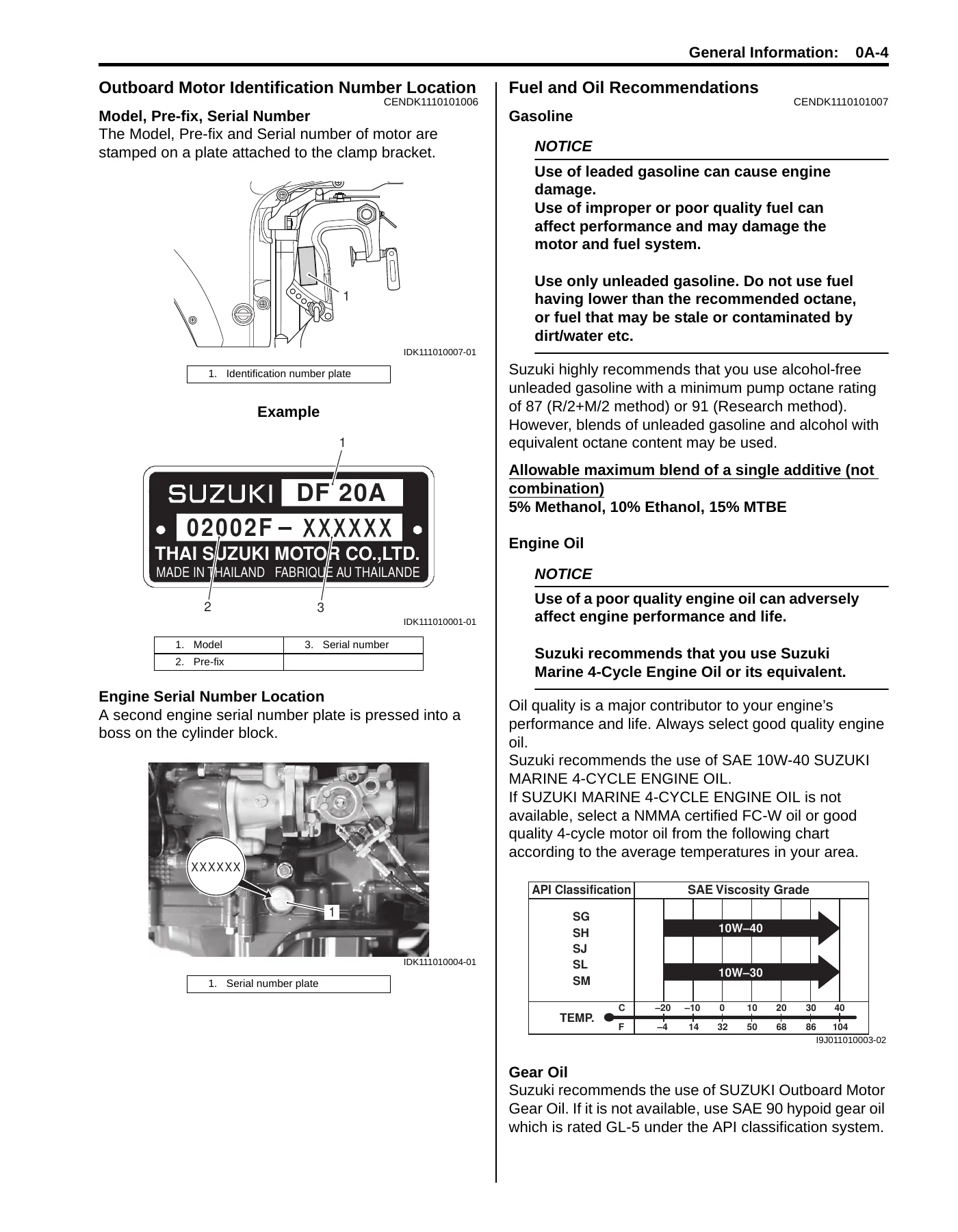
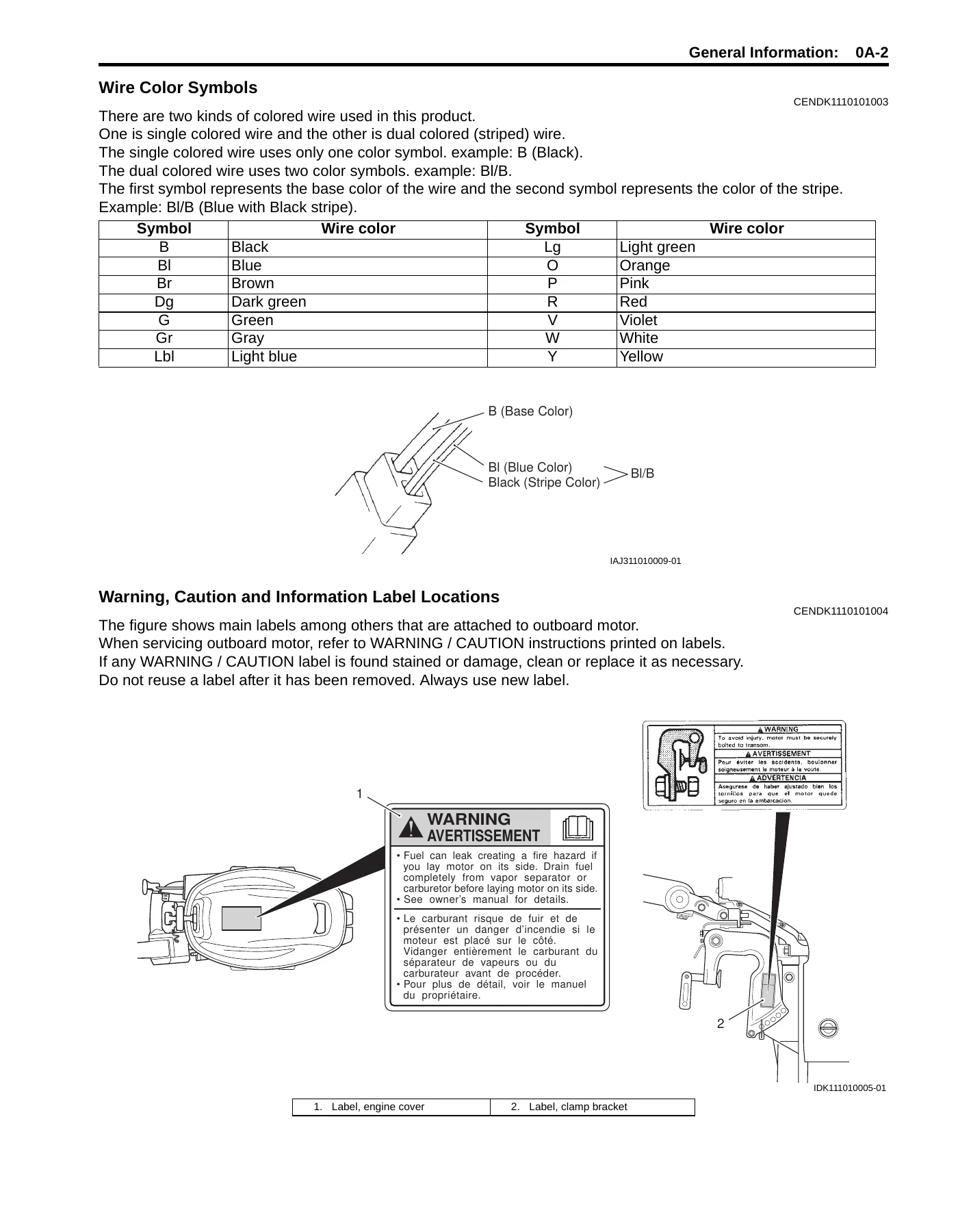
- Section 0 — General Information: General description, symbols, abbreviations, wire color symbols, warning and information label locations, outboard motor identification number location, fuel and oil recommendations, break-in procedures, propeller selection guide, battery requirement, specifications, service data, tightening torque specifications, special tools and equipment; Maintenance and Tune-Up: periodic maintenance schedule chart, lubrication points, engine oil level and oil/filter change, gear oil change, spark plug removal/inspection, valve clearance inspection and adjustment, timing belt inspection and replacement, idle speed and IAC duty inspection, ignition timing inspection, breather and fuel line inspection, low pressure fuel filter inspection, water pump and impeller inspection, propeller/nut/cotter pin inspection, anodes inspection, battery inspection, bolts and nuts inspection, oil pressure check, cylinder compression pressure check
- Section 1 — Power Head: Engine Control (1A) including ECM, caution system, self-diagnostic system, fail-safe system, oil change reminder system and troubleshooting; Engine Electrical Devices (1C); Power Unit Mechanical (1D) including cylinder head, camshaft, pistons, crankshaft, conrods and bearings; Power Unit Lubrication (1E); Power Unit Cooling System (1F); Fuel System (1G) including electronic fuel injection, fuel vapor separator, high and low pressure fuel pumps, injectors and fuel pressure testing; Ignition System (1H); Starting System (1I); Manual Starting System (1J); Charging System (1K)
- Section 2 — Mid Unit: Precautions and Housing and Bracket (2A) — lower side covers, tiller handle, throttle control cable, steering friction adjuster, engine holder, driveshaft housing, mounts, clamp/swivel/steering brackets
- Section 3 — Lower Unit: Precautions and Right Hand Rotation Unit (3A) — lower unit components, propeller, water pump, gearcase disassembly, pinion bearing, oil seals, lower unit assembly and gear shimming/adjustment
- Section 4 — Wire / Hose Routing: Wire Routing (4A) with wiring diagram and harness routing; Fuel / Water Hose Routing (4B)
Together these sections make up a full service reference. The General Information section alone gives you the specification tables, service data and torque values that the rest of the manual references. The Power Head section walks through the ECM-controlled fuel injection, ignition and idle air systems; the mechanical rebuild of the cylinder head, camshaft, pistons and crankshaft; the lubrication and cooling circuits; and the starting and charging systems for both manual and electric start models. The Mid Unit section covers the tiller handle, steering friction adjuster, engine holder and driveshaft housing. The Lower Unit section covers the right-hand rotation gearcase, water pump, propeller shaft, forward/reverse gears and the shimming procedure used to set gear backlash and tooth contact.
What This Manual Lets You Do
With this Suzuki DF15A DF20A repair manual on hand, you can carry out the full scheduled maintenance program — engine oil and filter changes, gear oil changes, spark plug service, valve clearance inspection and adjustment, timing belt inspection and replacement, idle speed and IAC duty checks, ignition timing, water pump and impeller service, anode inspection and battery checks — using the intervals and values printed in the manual.
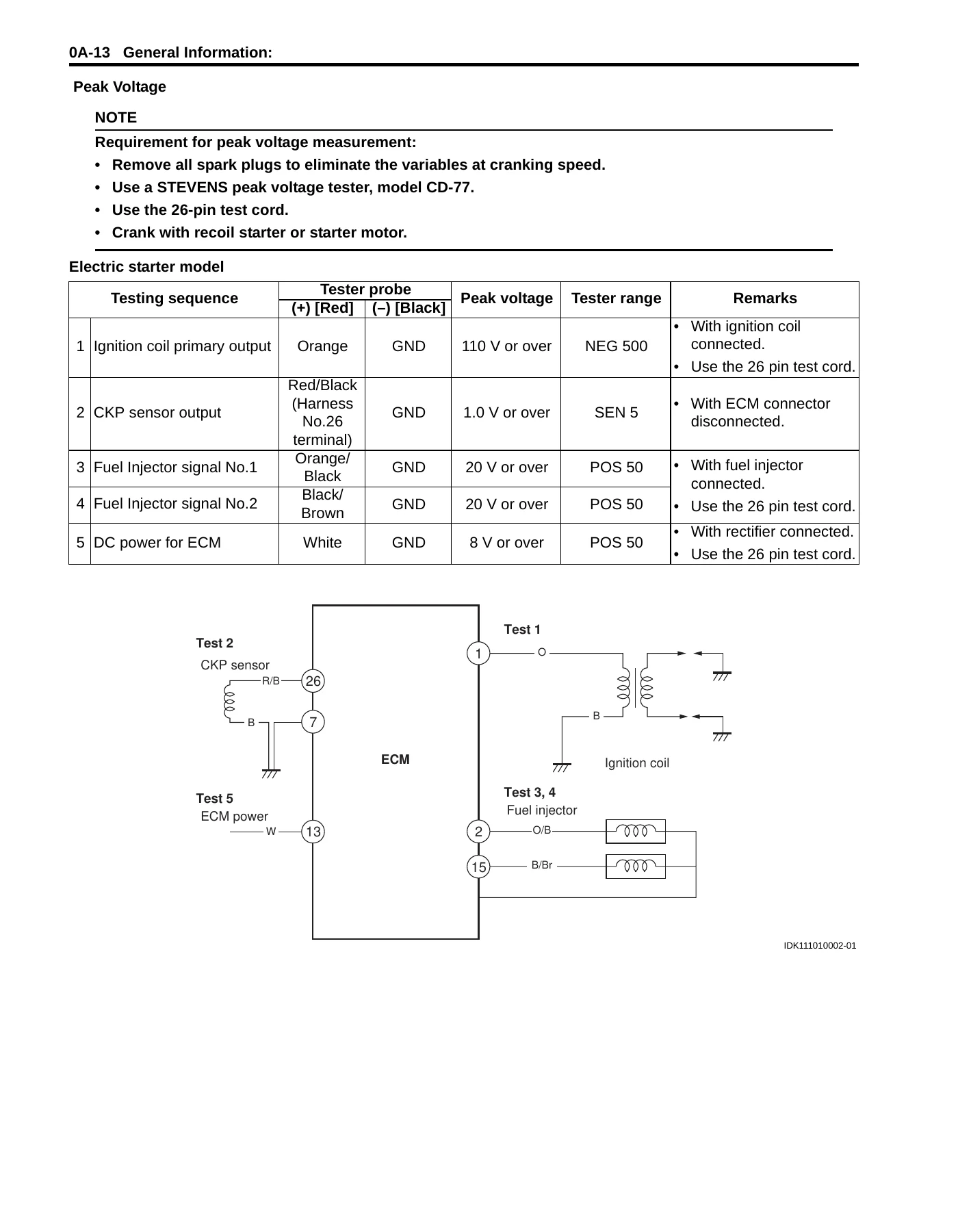
Beyond maintenance, the manual supports real diagnostic and repair work. Self-diagnostic codes are listed with their lamp flash patterns and fail-safe behaviour, so you can trace a fault in the MAP sensor, cylinder temperature sensor, IAT sensor, CKP sensor, CMP sensor, air intake system, fuel injector, throttle position sensor or rectifier/regulator. The fuel system chapter covers the low pressure fuel pump, high pressure fuel pump, fuel vapor separator, fuel cooler, delivery pipe and injectors, including fuel pressure testing. The electrical chapters give resistance and peak voltage values for the CKP sensor, CMP sensor, ignition coil, IAC valve, injectors, starter motor relay and battery relay.
For major work, the power unit can be removed and reinstalled following the illustrated procedure, the cylinder head can be disassembled and its valve seats, guides and springs measured against service limits, and the crankshaft and main bearings checked with Plastigauge. The lower unit can be stripped down to the gears and rebuilt with the correct shims to restore proper backlash and tooth contact.
Why Correct Procedures and Specifications Matter
These are fuel-injected, ECM-controlled four-stroke outboards, and small errors carry real consequences. An incorrect valve clearance affects compression and valve life. Wrong gear shimming in the lower unit leads to noise, overheating and eventual gear failure. Mis-torqued cylinder head or conrod bolts can cause leaks or fastener failure. Incorrect fuel pressure or a misdiagnosed sensor can leave the engine hard to start, unstable at idle or down on power. This manual gives you the actual figures — torque values, service limits, clearances, resistances, peak voltages, pressures and temperatures — so the work is done to Suzuki’s specification rather than by guesswork.
IMAGES PREVIEW
Instant PDF Delivery
The 2012 2013 Suzuki DF15A DF20A 4-stroke outboard repair manual is delivered as an instant PDF download after payment. There is no shipping and no waiting for a physical book. You can open it on a workshop laptop, tablet or phone, print the pages you need for the bench, and keep the file for future reference.
Reviews
There are no reviews yet.