2017 Harley Davidson Dyna Models Service Manual – PDF DOWNLOAD
Original price was: $89.95.$19.95Current price is: $19.95.
2017 Harley Davidson Dyna Models Service Manual – PDF DOWNLOAD
Description
2017 Harley Davidson Dyna Models Service Manual – PDF DOWNLOAD
IMAGES PREVIEW OF THE MANUAL:

DESCRIPTION:
Official OEM Service Manual · PDF Download
2017 Harley-Davidson Dyna Models — Complete Service Manual
Factory-approved repair procedures for all 2017 Dyna variants
FXDF Fat Bob
FXDL Low Rider
FXDLS Low Rider S
FXDWG Wide Glide
Twin Cam 96
Twin Cam 103
Twin Cam 110
The complete factory service manual for every 2017 Harley-Davidson Dyna model. This is the same document used by authorised Harley-Davidson dealership technicians — covering everything from routine maintenance intervals to full engine-out bottom-end rebuilds, with every torque value, wear limit, and wiring diagram you need to do the job right the first time.
7 Technical chapters | 5 Dyna model variants | 3 Engine displacements | 2 Wiring appendices |
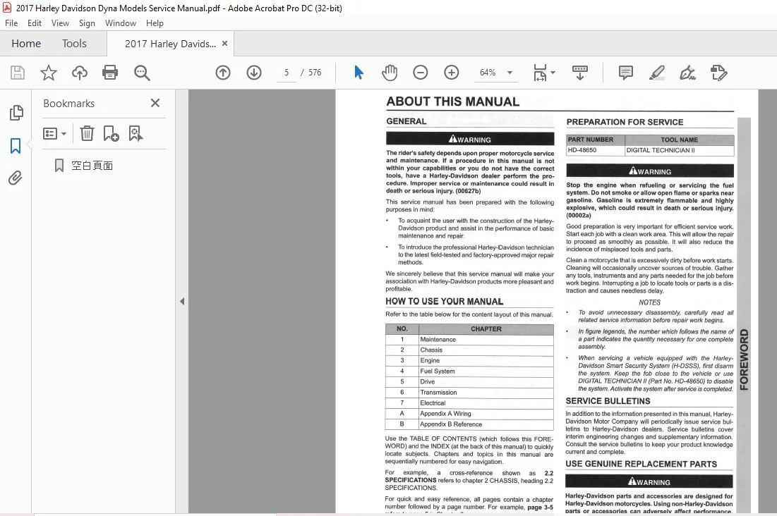
What’s covered — chapter by chapter
Chapter 1 Maintenance Schedules, oil & filter, air cleaner, tires, wheels, brakes, battery, clutch, drive belt, throttle cables, spark plugs, steering, suspension, storage — 24 sections |
Chapter 2 Chassis Front & rear wheels, sealed bearings, wheel lacing & truing, brake calipers & master cylinders, ABS module (EHCU), front fork, steering head, shock absorbers, handlebars, fenders, seat, footboards, jiffy stand — 36 sections |
Chapter 3 Engine Twin Cam 96 / 103 / 110 Full top-end overhaul, cam compartment service, engine removal & installation, cylinder heads, pistons, cylinders, camshafts, oil pump, crankcase, flywheel & connecting rods — 32 sections |
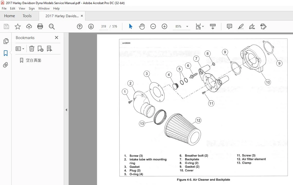
Chapter 4 Fuel System Air cleaner assemblies, fuel tank, EFI sensors (TPS, IAT, IAC, MAP, TMAP, TGS), induction modules, fuel injectors, oxygen sensor, fuel pump, exhaust system, evaporative emissions — 22 sections |
Chapter 5 Drive Primary chaincase cover & housing, drive components, clutch (partial and complete rebuild), transmission sprocket, drive belt — 8 sections |
Chapter 6 Transmission 6-Speed Power flow (neutral through 6th gear), shifter linkage adjustment, clutch release cover, complete transmission disassembly & assembly, main drive gear & bearing, transmission case — 8 sections |
Chapter 7 Electrical ECM, BCM, security siren, starter, headlamp, tail lamp, turn signals, all sensors (CKP, VSS, WSS, oil pressure, neutral), alternator, wiring harness, handlebar control modules, H-DSSS security system — 39 sections |
Appendix A & B Wiring Diagrams & Reference Complete 2017 Dyna wiring diagrams, connector locations, wire color codes, diagram symbols, length/fluid/torque conversion tables, acronyms & abbreviations glossary, comprehensive index |
Why this manual
| ✓ Factory torque values for every fastener in every chapter | ✓ Service wear limits for engine, transmission and drivetrain |
| ✓ Model-specific procedures flagged for each variant (FXDB, FXDF, FXDL, FXDLS, FXDWG) | ✓ Separate TC96/103 and TC110 procedures where specs differ |
| ✓ Complete OEM wiring diagrams with connector locations and wire color codes | ✓ Troubleshooting guides for engine, electrical, transmission and handling |
| ✓ HDI (India) and JPN (Japan) market variant callouts included | ✓ Sequential section numbering with cross-reference system for fast navigation |
How to navigate this manual
Sections use a chapter.section numbering system — for example, 2.1 means Chapter 2 (Chassis), heading 1 (Specifications). Page references follow the same logic: page 3-5 is page 5 within Chapter 3 (Engine).
Use the Table of Contents for system-level navigation and the comprehensive alphabetical Index at the back for quick part or procedure lookups. All acronyms and abbreviations are defined in the Appendix B Glossary.
⚡ Instant PDF download upon payment
No shipping. No waiting. Opens on any device — phone, tablet, laptop or desktop. Print individual pages or chapters as needed.
TABLE OF CONTENTS:
2017 Harley Davidson Dyna Models Service Manual – PDF DOWNLOAD
2017 Harley-Davidson Dyna Models — Service Manual
Complete Table of Contents · All Dyna Model Variants: FXDB · FXDF · FXDL · FXDLS · FXDWG
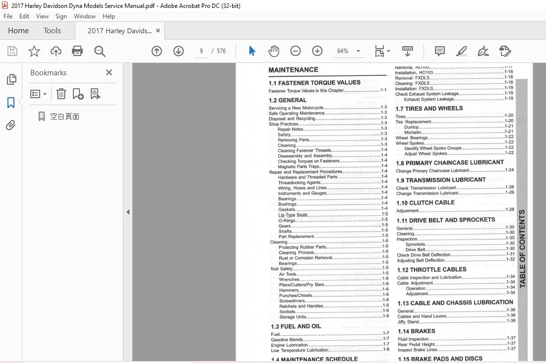
Chapter 1 — Maintenance Sections 1.1 – 1.24
| 1.1 | Fastener Torque Values | Complete torque specifications for all maintenance fasteners |
| 1.2 | General Shop Practices | Safe operating maintenance, disposal, repair notes, cleaning, hardware, seals, bearings, gaskets, tool safety |
| 1.3 | Fuel and Oil | Fuel specs, gasoline blends, engine lubrication, low-temperature lubrication |
| 1.4 | Maintenance Schedule | Complete general service interval schedule |
| 1.5 | Engine Oil and Filter | Cold/hot oil level check, oil and filter change procedure |
| 1.6 | Air Cleaner and Exhaust System | Removal/installation for all models including HD103, FXDLS; exhaust leakage check |
| 1.7 | Tires and Wheels | Tire replacement (Dunlop, Michelin), wheel bearings, spoke identification and adjustment |
| 1.8 | Primary Chaincase Lubricant | Change procedure for primary chaincase lubricant |
| 1.9 | Transmission Lubricant | Check and change transmission lubricant |
| 1.10 | Clutch Cable | Clutch cable adjustment procedure |
| 1.11 | Drive Belt and Sprockets | Cleaning, inspection, sprocket check, belt deflection check and adjustment |
| 1.12 | Throttle Cables | Cable inspection, lubrication and adjustment |
| 1.13 | Cable and Chassis Lubrication | Cables, hand levers, jiffy stand lubrication |
| 1.14 | Brakes | Fluid inspection, rear pedal height, brake line inspection |
| 1.15 | Brake Pads and Discs | Inspection, pad/disc measurement, rear and front caliper pad replacement |
| 1.16 | Spark Plugs | Spark plug inspection procedure |
| 1.17 | Steering Head Bearings | Bearing adjustment (measurement and fall-away methods), lubrication |
| 1.18 | Battery Maintenance | Cleaning, voltage test, charging, safety, battery tender connector, storage, removal/installation |
| 1.19 | Engine Mounts | Engine mount inspection procedure |
| 1.20 | Headlamp Alignment | Headlamp alignment for all models; separate procedure for FXDL |
| 1.21 | Suspension Adjustments (All but FXDLS) | Shock absorber preload adjustment |
| 1.22 | Suspension Adjustments (FXDLS) | FXDLS-specific shock absorber preload adjustment |
| 1.23 | Storage | Placing in storage and removal from storage procedures |
| 1.24 | Troubleshooting | Engine, lubrication system, electrical, transmission, handling, brakes — symptom/cause guide |
Chapter 2 — Chassis Sections 2.1 – 2.36
| 2.1 | Fastener Torque Values | All chassis torque specifications |
| 2.2 | Specifications | Chassis and tire specifications |
| 2.3 | Vehicle Identification Number (VIN) | VIN decoding and location |
| 2.4 | Front Wheel | Removal, disassembly (cast and laced wheel), inspection, assembly, installation |
| 2.5 | Rear Wheel | Removal, disassembly, inspection, assembly, installation |
| 2.6 | Sealed Wheel Bearings | Inspect, remove and install sealed wheel bearings |
| 2.7 | Wheel Lacing | Angle flange hub, straight flange hub (single and dual hole circle) lacing procedures |
| 2.8 | Checking and Truing Wheels | Radial and lateral runout, rim offset, truing laced wheels |
| 2.9 | Vehicle Alignment | Vehicle alignment inspection procedure |
| 2.10 | Front Brake Master Cylinder | Removal, disassembly, cleaning, inspection, assembly, installation |
| 2.11 | Front Brake Caliper | Removal, disassembly, cleaning, inspection, repair, assembly, installation |
| 2.12 | Rear Brake Master Cylinder | Removal, disassembly, cleaning, inspection, assembly, installation |
| 2.13 | Rear Brake Caliper | Removal, disassembly, cleaning, inspection, repair, assembly, installation |
| 2.14 | Brake Lines | Front master cylinder to caliper, ABS module lines (front and rear), rear caliper lines |
| 2.15 | ABS Module (EHCU) | Electro-Hydraulic Control Unit removal and installation |
| 2.16 | Bleeding Brakes | Complete brake bleeding procedure |
| 2.17 | Tires | Removal, inspection, installation (tube and tubeless), runout check, wheel balancing (static vs dynamic) |
| 2.18 | Front Fork | Oil seal service, disassembly for standard and FXDLS cartridge fork, cleaning, assembly, installation |
| 2.19 | Steering Head | Removal, inspection, disassembly, bearing race removal, assembly, installation |
| 2.20 | Belt Guard and Debris Deflector | Belt guard and debris deflector removal and installation |
| 2.21 | Cable Throttle Control | Removal, cleaning, inspection, assembly, throttle cable routing |
| 2.22 | Shock Absorbers | Removal, inspection, installation |
| 2.23 | Rear Fork | Removal, disassembly, cleaning, inspection, assembly, installation |
| 2.24 | Cable Clutch Control | Removal and installation |
| 2.25 | Handlebar: FXDB, FXDF, FXDLS, FXDWG | Handlebar and riser removal and installation |
| 2.26 | Handlebar: FXDL | FXDL handlebar removal, installation, and riser adjustment |
| 2.27 | Speed Screen: FXDLS | Speed screen removal and installation |
| 2.28 | Front Fender | Front fender removal and installation |
| 2.29 | Rear Fender | Model-specific procedures: FXDL, FXDB, FXDLS, FXDWG (incl. sissy bar), FXDF |
| 2.30 | Seat | Seat and seat strap removal/installation for all models; FXDL lumbar pad |
| 2.31 | Footboards and Footrests | Rider footboards, mid controls, forward controls, passenger footrests |
| 2.32 | Jiffy Stand | Cleaning; jiffy stand sensor removal/installation (HDI models) |
| 2.33 | Fork Lock | Fork lock removal and installation |
| 2.34 | Engine Mounts | Front and rear isolator removal and installation |
| 2.35 | Saree Guard: India Models | Saree guard removal and installation (HDI markets) |
| 2.36 | Medallions, Badges and Tank Emblems | Removal and installation of decorative emblems |
Chapter 3 — Engine Sections 3.1 – 3.32 · Twin Cam 96 / 103 / 110
| 3.1 | Fastener Torque Values | All engine fastener torque specifications |
| 3.2 | Specifications | Engine specifications |
| 3.3 | Service Wear Limits | General engine wear limits |
| 3.4 | Engine Oil Flow | Oil feed, top end, bottom end, oil return flow diagrams |
| 3.5 | Oil Pump Operation | Oil pump operation principles |
| 3.6 | Breather Operation | Engine breather system operation |
| 3.7 | Oil Pressure | Oil pressure indicator lamp, oil pressure check procedure |
| 3.8 | Troubleshooting | Valve train noise diagnosis, compression test, cylinder leakdown test, smoking engine diagnosis |
| 3.9 | How to Use this Section | Top end and bottom end repair guidance, typical symptoms |
| 3.10 | Top End Service | Engine in chassis and engine removed from chassis procedures |
| 3.11 | Cam Compartment Service | Camshaft replacement procedure |
| 3.12 | Stripping Motorcycle for Service | Strip procedure for cam compartment service and complete top end service |
| 3.13 | Assembling After Service | Reassembly sequence after cam compartment and top end service |
| 3.14 | Removing Engine from Chassis | Complete engine removal procedure |
| 3.15 | Installing Engine in Chassis | Complete engine installation procedure |
| 3.16 | Top End Overhaul: Disassembly | Rocker covers, rocker arm support plate, pushrods, lifters, cylinder head, cylinder, piston |
| 3.17 | Breather Assembly | Disassembly, cleaning, inspection, assembly |
| 3.18 | Rocker Arm Support Plate | Disassembly, rocker shaft fit, bushing replacement, assembly |
| 3.19 | Pushrods, Lifters and Covers | Disassembly, cleaning, lifter inspection, pushrod cover assembly |
| 3.20 | Cylinder Head: Twin Cam 96 / 103 | Valve sealing inspection, disassembly, valve guides, seats, springs, guide replacement, refacing, assembly |
| 3.21 | Cylinder Head: Twin Cam 110 | TC110-specific cylinder head repair procedures |
| 3.22 | Cylinder: Twin Cam 96 / 103 | Cleaning, inspection, deglazing, boring and honing |
| 3.23 | Cylinder: Twin Cam 110 | TC110 cylinder bore finished size specifications |
| 3.24 | Piston: Twin Cam 96 / 103 | Piston rings, cleaning, inspection, ring gap check, ring installation |
| 3.25 | Piston: Twin Cam 110 | TC110 piston clearance check |
| 3.26 | Top End Overhaul: Assembly | Piston, cylinder, head, pushrods, lifters, rocker arm, breather and rocker cover assembly |
| 3.27 | Cam Compartment and Components | Cam chain, sprockets, support plate, camshafts, oil pressure relief valve, cam needle bearings |
| 3.28 | Oil Pump | Oil pump removal, cleaning, inspection, installation |
| 3.29 | Crankcase Disassembly and Repair | Main bearings (left/right), piston jets, sprocket shaft bearing inner race, cylinder studs, pipe plugs |
| 3.30 | Flywheel and Connecting Rods | Symptom diagnosis, crankshaft runout measurement (installed and removed) |
| 3.31 | Crankcase Assembly | Complete crankcase assembly procedure |
| 3.32 | Oil Pan | Oil pan removal and installation |
Chapter 4 — Fuel System Sections 4.1 – 4.22
| 4.1 | Fastener Torque Values | Fuel system torque specifications |
| 4.2 | Specifications | Fuel system specifications |
| 4.3 | Air Cleaner Assembly (All but FXDLS) | Removal/installation for standard models and HD103; HDI backplate assembly |
| 4.4 | Air Cleaner Assembly: FXDLS | FXDLS-specific air cleaner disassembly and assembly |
| 4.5 | Fuel Tank | Removal, cleaning, inspection, installation, vapor valve |
| 4.6 | Twist Grip Sensor (TGS): FXDLS | TGS removal and installation |
| 4.7 | Engine Temperature Sensor (ET) | Removal and installation |
| 4.8 | Induction Module (All but FXDLS) | Removal and installation |
| 4.9 | Throttle Position Sensor (TPS) | Removal and installation (all but FXDLS) |
| 4.10 | Intake Air Temperature Sensor (IAT) | Removal and installation (all but FXDLS) |
| 4.11 | Idle Air Control (IAC) | Removal and installation (all but FXDLS) |
| 4.12 | Manifold Absolute Pressure Sensor (MAP) | Removal and installation (all but FXDLS) |
| 4.13 | Fuel Injectors (All but FXDLS) | Removal and installation |
| 4.14 | Induction Module: FXDLS | FXDLS induction module removal and installation |
| 4.15 | TMAP Sensor: FXDLS | Temperature Manifold Absolute Pressure sensor removal/installation |
| 4.16 | Fuel Injectors: FXDLS | FXDLS fuel injector removal and installation |
| 4.17 | Oxygen Sensor | Removal and installation |
| 4.18 | Fuel Pump | Removal, fuel filter, regulator, inlet sock, pump disassembly and assembly, installation |
| 4.19 | Fuel Pressure Test | Fuel pressure testing procedure |
| 4.20 | Exhaust System | Model-specific removal and installation: FXDB, FXDL (HDI/JPN), FXDLS, FXDF, FXDWG |
| 4.21 | Intake Leak Test | Leak tester assembly, adjustment and test procedure |
| 4.22 | Evaporative Emissions Control | Charcoal canister removal and installation |
Chapter 5 — Drive Sections 5.1 – 5.8
| 5.1 | Fastener Torque Values | Drive system torque specifications |
| 5.2 | Specifications | Drive system specifications |
| 5.3 | Primary Chaincase Cover | Removal and installation |
| 5.4 | Drive Components | Drive component removal and installation |
| 5.5 | Primary Chaincase Housing | Removal, mainshaft bearing/seal, mainshaft bearing inner race, shifter shaft bushing |
| 5.6 | Clutch | Clutch pack service, partial and complete disassembly/assembly procedures |
| 5.7 | Transmission Sprocket | Removal, cleaning, inspection, installation |
| 5.8 | Drive Belt | Drive belt removal and installation |
Chapter 6 — Transmission Sections 6.1 – 6.8 · 6-Speed
| 6.1 | Fastener Torque Values | Transmission torque specifications |
| 6.2 | Specifications and Wear Limits | Transmission specifications and service wear limits |
| 6.3 | Power Flow | Power flow diagrams: neutral, 1st through 6th gear |
| 6.4 | Shifter Linkage | Shifter rod adjustment for forward and mid-controls |
| 6.5 | Cable Clutch Release Cover | Removal, disassembly, cleaning, inspection, assembly, installation |
| 6.6 | Transmission Assembly | Shifter cam/forks, mainshaft, countershaft, bearing housing bearings — full disassembly and assembly |
| 6.7 | Main Drive Gear and Bearing | Removal, needle bearing replacement, gear and bearing installation, large seal installation |
| 6.8 | Transmission Case | Removal, installation, disassembly, shifter pawl lever, countershaft needle bearing replacement |
Chapter 7 — Electrical Sections 7.1 – 7.39
| 7.1 | Fastener Torque Values | Electrical system torque specifications |
| 7.2 | Specifications | Electrical system specifications |
| 7.3 | Electrical Caddy | Removal and installation |
| 7.4 | Electronic Control Module (ECM) | ECM replacement, removal, installation |
| 7.5 | Body Control Module (BCM) | BCM removal and installation |
| 7.6 | Security Siren | Removal and installation |
| 7.7 | Spark Plug Cables | Inspection, removal, installation |
| 7.8 | Fuses | Fuse identification and replacement |
| 7.9 | Ignition Switch | Removal and installation; separate procedures for FXDL and all others |
| 7.10 | Battery Tray and Battery Cables | Battery tray removal/installation, cable routing |
| 7.11 | Starter | Removal, drive assembly, disassembly, inspection, solenoid service, installation |
| 7.12 | Headlamp | Single and dual bulb removal/installation; headlamp assembly for all models; FXDL visor |
| 7.13 | Tail Lamp | Model-specific procedures: FXDL, FXDWG, FXDF; license plate lamp; bracket service for FXDB/FXDLS |
| 7.14 | Turn Signals | Bullet style bulb replacement, front and rear lamp housing replacement |
| 7.15 | Crank Position Sensor (CKP) | Removal and installation |
| 7.16 | Automatic Compression Release (ACR) | Removal and installation |
| 7.17 | Voltage Regulator | Removal and installation |
| 7.18 | Alternator | Removal, cleaning, inspection, installation |
| 7.19 | Fuel Gauge | Fuel gauge removal |
| 7.20 | Fuel Gauge Sender | Sender removal and installation |
| 7.21 | Instruments: FXDF | Speedometer removal and installation |
| 7.22 | Instruments: FXDB, FXDWG | Instrument removal and installation |
| 7.23 | Instruments: FXDL, FXDLS | Instrument removal and installation |
| 7.24 | Vehicle Speed Sensor (VSS) | Removal and installation |
| 7.25 | Wheel Speed Sensors (WSS) | Front and rear wheel speed sensor removal and installation |
| 7.26 | Indicator Lamps | Removal and installation by model: FXDF, FXDB, FXDWG, FXDLS |
| 7.27 | Neutral Switch | Removal and installation |
| 7.28 | Oil Pressure Switch | Removal and installation |
| 7.29 | Rear Stop Lamp Switch | Removal and installation |
| 7.30 | Horn | Inspection and replacement; separate procedures for FXDL and FXDLS |
| 7.31 | Main Wiring Harness | Complete wiring harness removal and installation |
| 7.32 | Handlebar Control Modules | General information and repair procedures |
| 7.33 | Left Handlebar Control (All but FXDLS) | Removal, clutch switch replacement, installation |
| 7.34 | Right Handlebar Control (All but FXDLS) | Removal, front brake switch replacement, installation |
| 7.35 | Left Handlebar Control: FXDLS | FXDLS left control removal and installation |
| 7.36 | Right Handlebar Control: FXDLS | FXDLS right control removal and installation |
| 7.37 | H-DSSS Maintenance | Fob battery replacement schedule, smart siren battery replacement |
| 7.38 | Personal Identification Number (PIN) | PIN changing and modification procedures |
| 7.39 | H-DSSS Actuation | Sidecar configuration, activation, fob assignment |
Appendices & Reference Appendix A · B
| App. A | Wiring Diagrams | Connector locations, function/location index, wire color codes, diagram symbols, complete 2017 Dyna wiring diagrams |
| App. B | Reference Tables | Length, fluid and torque conversion tables (US, metric, British Imperial); acronyms and abbreviations glossary |
| Index | Tools, Torque Values & Full Index | Special tools list, master torque value tables, comprehensive alphabetical index |
PLEASE NOTE:
- This is not a physical manual but a digital manual – meaning no physical copy will be couriered to you. The manual can be yours in the next 2 mins as once you make the payment, you will be directed to the download page IMMEDIATELY.
- This is the same manual used by the dealers inorder to diagnose your vehicle of its faults.
- Require some other service manual or have any queries: please WRITE to us at [email protected]
S.V