
2018 Renault Trafic Workshop Repair Manual PDF – 2019 Pages
Original price was: $44.95.$26.95Current price is: $26.95.
Comprehensive 2019-page English Renault Trafic workshop repair manual dated February 2018, covering mechanical, engine, cooling, diesel injection, clutch, gearbox, brakes, steering, suspension, electrical, HVAC, bodywork, maintenance and diagnostic procedures with exploded views, special-tool references and technical data.
Description
2018 Renault Trafic Workshop Repair Manual PDF – 2019 Pages
The 2018 Renault Trafic Workshop Repair Manual PDF – 2019 Pages is a substantial technical repair reference for the Renault Trafic. Dated February 2018, this English-edition manual brings together detailed removal and refitting procedures, repair instructions, exploded assemblies, maintenance information, diagnostic operations and workshop data across the vehicle. Its scope extends from routine service work to engine, transmission, braking, steering, electrical, climate-control and structural body repairs.
Procedures are laid out in practical workshop sequence, commonly separating removal preparation, removal, refitting preparation, refitting and final checks. Throughout the Renault Trafic workshop manual, warnings and cautions identify operations requiring special attention, while individual procedures reference the applicable special tools, diagnostic equipment, replacement parts, tightening information and related assembly diagrams.
File Details
- Manual type: Workshop Repair Manual
- Brand / model: Renault Trafic
- Language: English / Edition Anglaise
- Page count: 2019 pages
- File format: PDF
- Document reference: 77 11 303 302
- Date: February 2018
Workshop Procedures and Repair Information
This Renault Trafic 2018 workshop repair manual is built around individual service operations rather than brief owner-level explanations. Mechanical jobs show the components that must first be removed for access, the correct order of disassembly, cleanliness precautions, components or seals that must be renewed, and the checks required after reassembly. Many procedures also direct the technician to associated exploded views and workshop specifications.
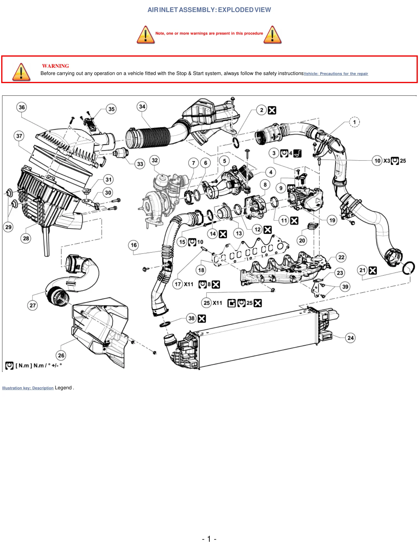
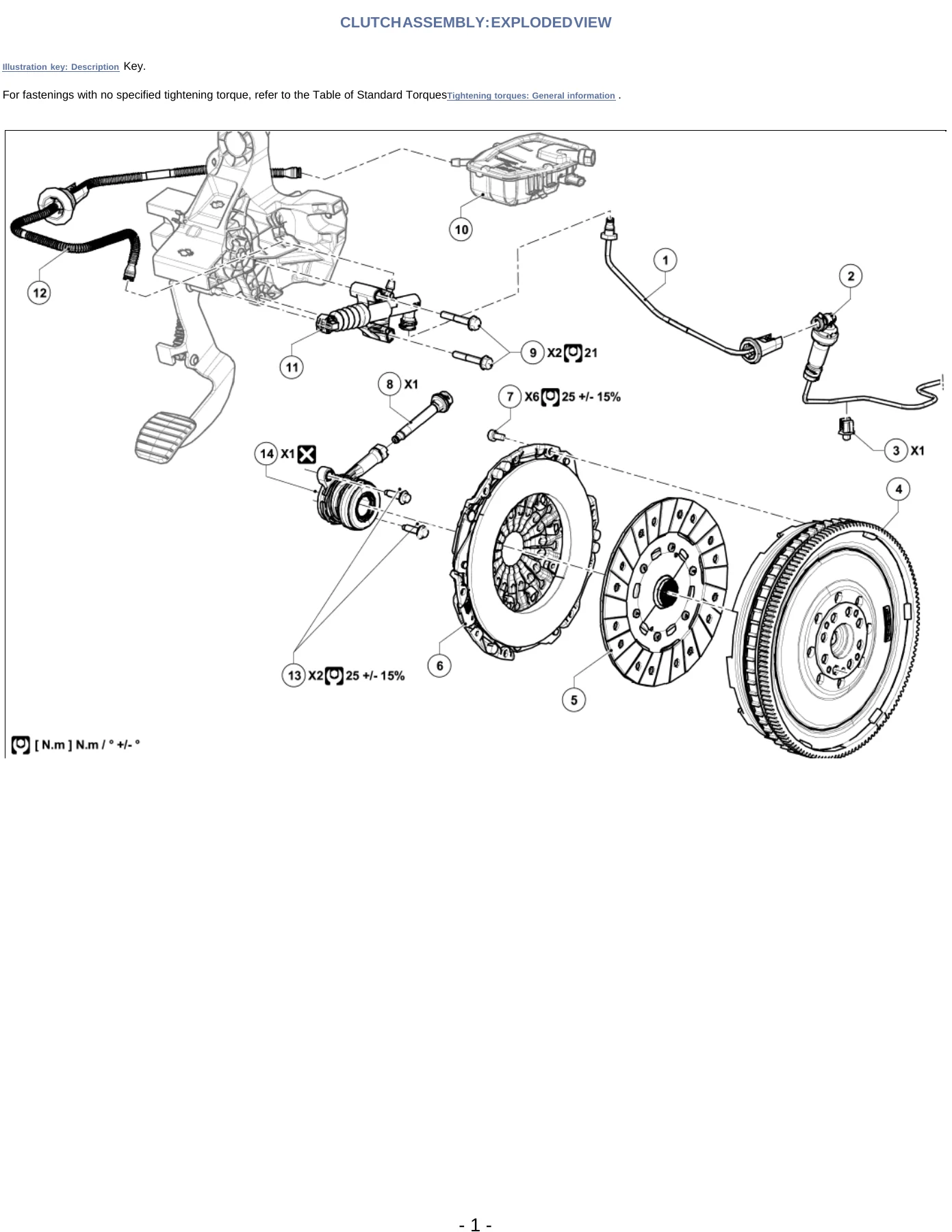
The manual contains extensive illustrated component information. Examples include air inlet, clutch, driveshaft, dashboard, cooling and other assemblies shown in exploded form, with numbered components tied to their designations. These views are useful when identifying the relationship between parts before beginning a repair or while checking that clips, seals, fasteners, pipes and related components are returned to their proper positions.
Special tooling is identified where a job requires it. The manual references Renault workshop tools from families such as Mot., Ms., Bvi., Dir., Car., Tav., Rou. and Fre., as well as equipment including diagnostic tools, refrigerant charging stations, bleeding equipment, component jacks and other workshop apparatus. Where diagnostic configuration is part of a replacement procedure, the instructions identify before-repair or after-repair operations and the relevant computer or component selection.
Chapters and Systems Covered
- General information and fault finding
- Repair precautions, workshop methods and noise fault finding
- Diagnostic-tool use and fault-finding procedures
- Maintenance
- Maintenance operational instructions and service checks
- Maintenance values, oils, coolant, brake fluid and tightening data
- Engine and cylinder block assembly
- Cylinder block, crankshaft, pistons, connecting rods and flywheel
- Cylinder head, camshafts, valves, rocker components and associated sensors
- Top and front of engine
- Accessories belt and crankshaft accessories pulley
- Engine accessory components and related removal/refitting work
- Fuel mixture and air inlet
- Air filter, air flowmeter, intercooler and inlet pipes
- Damper valve, swirl valve, inlet distributor and turbocharger-related intake components
- Diesel injection
- Diesel injection computer and associated diagnostic procedures
- Diesel injectors, injector fuel return rail and high-pressure circuit precautions
- Cooling system
- Coolant circuit assembly, coolant pump and coolant temperature sensor
- Cooling radiator, draining, refilling, bleeding and system checks
- Exhaust
- Exhaust connecting components, seals and heat-shield precautions
- Cutting, joining and leak-checking procedures where specified
- Clutch
- Clutch assembly and hydraulic clutch circuit
- Clutch master cylinder, clutch pedal and clutch housing bearing
- Manual gearbox and driveshafts
- Gearbox-related workshop operations and differential output seals
- Left- and right-hand driveshaft components, gaiters, bearings and seals
- Braking system
- Brake circuit operating information and braking circuit bleeding
- Brake pedal, brake servo and brake servo non-return valve
- Steering and axle systems
- Steering assembly procedures and axial ball joint linkage
- Rear axle removal/refitting, suspension-related operations and geometry checks
- Heating and ventilation
- Control panel, air distribution and air mixing controls
- Distribution unit, cabin filter and passenger-compartment fan components
- Air conditioning
- Compressor, condenser and expansion-valve circuit components
- Refrigerant pipes, dehydrator filter, draining, filling and leak checks
- Battery, starting and charging
- Battery and battery tray removal/refitting
- Alternator, starter and electrical connection procedures
- Control and signalling systems
- Steering-wheel controls, rotary switch and steering-wheel angle sensor
- Cruise control, speed limiter and associated pedal switches
- Electrical wiring
- Wiring precautions, repair-kit information and wiring repair methods
- Connector repair, sealing, checking and multiplex network repair
- Airbags and pretensioners
- Driver frontal airbag removal/refitting and safety procedures
- Airbag and pretensioner wiring repair information
- Bodywork and structural repair
- Body side, pillars, centre floor, cross members and roof structural components
- Complete and partial panel replacement, steel type and panel-thickness information
- Interior and exterior equipment
- Dashboard, seats, carpet, crew-cab partition and interior trim
- Door mirrors, mirror glass, casings and related fittings
Taken together, these sections give the technician a broad working reference for dismantling, repairing, replacing, refitting and checking Renault Trafic systems. The manual repeatedly connects individual procedures to related assemblies so that a larger repair can be followed across several operations rather than treating each component in isolation.
Maintenance Data, Torques and Service Checks
The 2018 Renault Trafic Workshop Repair Manual PDF includes workshop values alongside the procedures. The maintenance material contains engine-oil and coolant information, brake-fluid requirements and chassis service data, while individual repair operations supply applicable tightening values, dimensions, pressure settings and adjustment information. Examples throughout the document show torque-controlled work on electrical terminals, seats, body supports, sensors, brake connections and other assemblies.
Cooling-system service receives particularly detailed treatment, including draining, filling and bleeding methods, dedicated filling and pressure-test tools, coolant-protection criteria and post-fill operating checks. Brake work similarly includes a structured bleeding procedure with equipment requirements, pressure guidance, bleed order and final pedal and leak checks.
Diesel Injection and Diagnostic Operations
Diesel-system coverage goes beyond component location. Injector work includes high-pressure fuel-system safety precautions, injector identification by cylinder, replacement sealing components, injector-well cleaning and diagnostic programming after replacement where required. The diesel injection computer and other electronically controlled components include procedures that call for the diagnostic tool before or after repair.
The manual also covers electronically monitored components such as the air flowmeter, crankshaft position sensor, steering-wheel angle sensor and cruise-control inputs. These procedures are valuable when a physical replacement is only part of the job and the repair also requires a specified diagnostic-tool operation or an operational check.
Body and Structural Repair Coverage
A significant portion of this Renault Trafic repair manual addresses structural bodywork. Illustrated replacement procedures identify panels and reinforcements, material types such as mild steel and HSS, and panel thicknesses. Sections for the body side, centre floor, cross members, roof-related components and other structural areas show complete or partial replacement zones where applicable.
IMAGES PREVIEW
Body repair instructions also incorporate welding precautions, including protection of electrical and electronic equipment and the positioning of welding earth connections. This makes the manual useful not only for mechanical servicing but also for workshops handling accident repair and structural panel replacement.
Electrical Wiring and Supplementary Technical Information
The PDF incorporates additional Renault technical material alongside the Trafic-specific procedures. The electrical wiring repair material covers wiring-repair precautions, repair-kit tools and consumables, wire and sleeve selection, crimping and self-solder methods, heat-shrink operations, inspection of completed repairs, connector work, multiplex-network repairs and airbag/pretensioner wiring. Supplementary technical notes within the compilation may be marked for all types rather than being exclusive to the Trafic, so their stated application and procedure conditions should be followed when using those sections.
Other supplementary fault-finding information addresses workshop diagnosis of vehicle noises and provides structured checks covering areas such as the drivetrain, suspension, steering, engine, body and interior. This broad supporting material adds diagnostic context to the component-specific Renault Trafic workshop procedures.
Use This Manual for Confident Renault Trafic Repair Work
The 2018 Renault Trafic Workshop Repair Manual PDF – 2019 Pages supports a wide range of maintenance, diagnosis, dismantling, component replacement, mechanical repair, electrical work, climate-system service and structural bodywork. Having the illustrated procedures, special-tool references, tightening information, safety precautions and system-specific checks together helps reduce guesswork and makes it easier to follow the required sequence for complex jobs.
Use this Renault Trafic 2018 workshop manual when you need detailed repair instructions rather than a basic owner’s guide. Correct procedures and specifications matter when working with systems such as high-pressure diesel injection, brakes, steering, cooling, air conditioning, electrical wiring and structural body components, where an incorrect sequence or setting can affect the quality of the repair.
Delivered as an instant PDF download after purchase, there is no physical book and no shipping delay. Open the manual on a computer, tablet or other PDF-capable device, keep it available in the workshop, and print the pages you need for the job.
Reviews
There are no reviews yet.