Complete Rigging and Installation Reference for Yamaha Outboard Motors
2018 Yamaha Outboard Rigging Guide Worldwide Edition
The 2018 Yamaha Outboard Rigging Guide Worldwide Edition is the definitive technical authority for rigging, mounting, configuring, and wiring the complete line of 2018 Yamaha two-stroke and four-stroke outboard engines. From compact portable motors (2.5 HP to 25 HP) up through high-displacement inline, V6 4.2L, and 5.3L V8 outboards (F350), this extensive factory manual provides marine dealers, riggers, naval architects, and boat owners with exact mechanical clearances, structural mounting requirements, control system wiring, network hub topologies, and instrument setup procedures.
File Details
| Manual Type: | Factory Rigging Guide & Installation Manual |
| Brand & Manufacturer: | Yamaha Motor Co., Ltd. (Technical Publication Division) |
| Applicable Year / Edition: | 2018 Worldwide Edition (Global & Unified US/Canada Models) |
| Publication / Document Number: | 6YR-2819Y-E2 (Published March 2018) |
| File Format: | Portable Document Format (.PDF) |
| Language: | English |
| Page Count: | 316 Pages |
Chapters Covered
- Chapter 1 — Installation: Top cover pictographs, engine oil reminder tags, steel frame uncrating procedures, transom centerline layout, engine mounting heights, 4-stroke water level guidelines, twin-engine toe-out adjustment (7.5–15 m wake convergence), maximum boat speed estimation formula, overall motor dimensions (L1–L10, H1–H11, W1–W6, A1–A3, T1), and clamp bracket dimensions (B1–B13, C1–C3, D1–D4, AN1–AN2).
- Chapter 2 — Propellers: Propeller types and specifications (Standard Aluminum & Stainless Steel, Reliance Series, Talon SDS, Talon 4 SDS, Dual Thrust, Weedless, Saltwater Series II, Saltwater Series HS4, Saltwater Series XL/XL4, VMAX Series, Performance Series, High Performance Series), pitch/diameter identification, propeller selection criteria, comprehensive 2018 application charts with part numbers, and Wide-Open-Throttle (WOT) operating RPM range tables.
- Chapter 3 — Remote Controls: Mechanical and electronic control systems, 703 side mount remote control, 704 binnacle mount single/twin controls, 6X3 concealed mount controls, 6X5 triple binnacle controls, 6X6 Digital Electronic Control (DEC) binnacle units (single, twin, triple, quad helms), 6X7 concealed DEC controls, single/twin/triple/quad ignition switch panels, emergency stop lanyards, station selector switches, PTT switch panels, control cable length calculation and 15 N free-play adjustments (Push-to-Open and Pull-to-Open), remote attachment kits, steering hooks, steering guide kits, tie-bars, and 7-pin/10-pin/16-pin wiring harnesses.
- Chapter 4 — Tiller Handles: 6X4 Multi-Function Tiller Handle system architecture, regional handle assemblies and fitting kits (US, Japan, EU & ANZ), variable trolling RPM switch setup, LED warning indicators, integral PTT switches, immobilizer harness routing, steering friction assembly torque specifications, exploded diagrams, and complete schematic wiring diagrams.
- Chapter 5 — Conventional Gauge (6Y5 & 6Y7): Instrument mounting methods, analog tachometers (4-pole, 6-pole, and 12-pole rotary switch calibration), 6Y5 digital multifunction tachometers (dipswitch settings for trim sensor, pole count, and 2-stroke/4-stroke modes), mechanical and digital speedometers, pitot tube routing and water pressure dampers, fuel management meter (6Y5-8350F-B0) with fuel flow sensors and GPS NMEA 0183 input, analog trim meters, coolant pressure gauges, coolant temperature meters and cylinder head sensor installations, mechanical/digital hour meters, voltmeters, fuel meters, charge warning units, wire color codes, wiring diagrams, and harness interchangeability adapters for pre-2006 vs. 2007+ engines.
- Chapter 6 — Digital Network Gauge (6YC & 6Y8): Electronic Fuel Injected 4-stroke network compatibility, 6Y8 round multifunction gauges, 6YC color LCD display, optional transom/thru-hull multi-sensors, speed sensor kits, coolant pressure sensor kits, NMEA 2000 gateway integration, Analog Gauge Interface (AGI), main bus wires, pigtail bus wires, system power leads, multi-hubs, single inline hubs, terminating resistors, Y-COP immobilizer unit, multi-engine Port-to-Starboard ignition sequence recognition, NMEA 0183 sentences (RMC, DBT, MTW), troubleshooting, and function compatibility tables.
- Chapter 7 — CL7 Display (6YD): 7-inch color touchscreen Multi-Function Display architecture, mechanical and DEC engine compatibility, setup kits for 6X6, 6X7, 703, and 704 controls, 6-tank monitoring harness, internal chart and Wi-Fi features, conversion harnesses, multi-sensor integration, and complete schematic network wiring diagrams for single, twin, triple, and quad outboard applications across single-station and dual-station helms.
- Chapter 8 — Battery: Recommended battery capacities (CCA, MCA, RC, Ah ratings per engine displacement), maximum battery cable lengths and AWG conductor sizing, dual battery switch wiring, isolator lead connections, and multi-engine ground bonding configurations.
- Chapter 9 — Appendix: Model name designation decoding, fuel system vacuum pressure standards, portable and permanent fuel tank plumbing, primer bulbs, Pre-Delivery Inspection (PDI) workflows, standard and digital gauge rigging kit contents, immobilizer kits, and 2018 model year starting serial numbers.
Complete PDF Bookmark Tree
Complete Bookmarks
The complete bookmarks in the “2018 Yamaha Outboard Rigging Guide Worldwide Edition” are as follows:
PREFACEp. 3
CONTENTSp. 5
+INSTALLATIONp. 9
TOP COVER PICTOGRAPH DESCRIPTIONp. 10
ENGINE OIL REMINDER TAG (4-STROKE ENGINES)p. 10
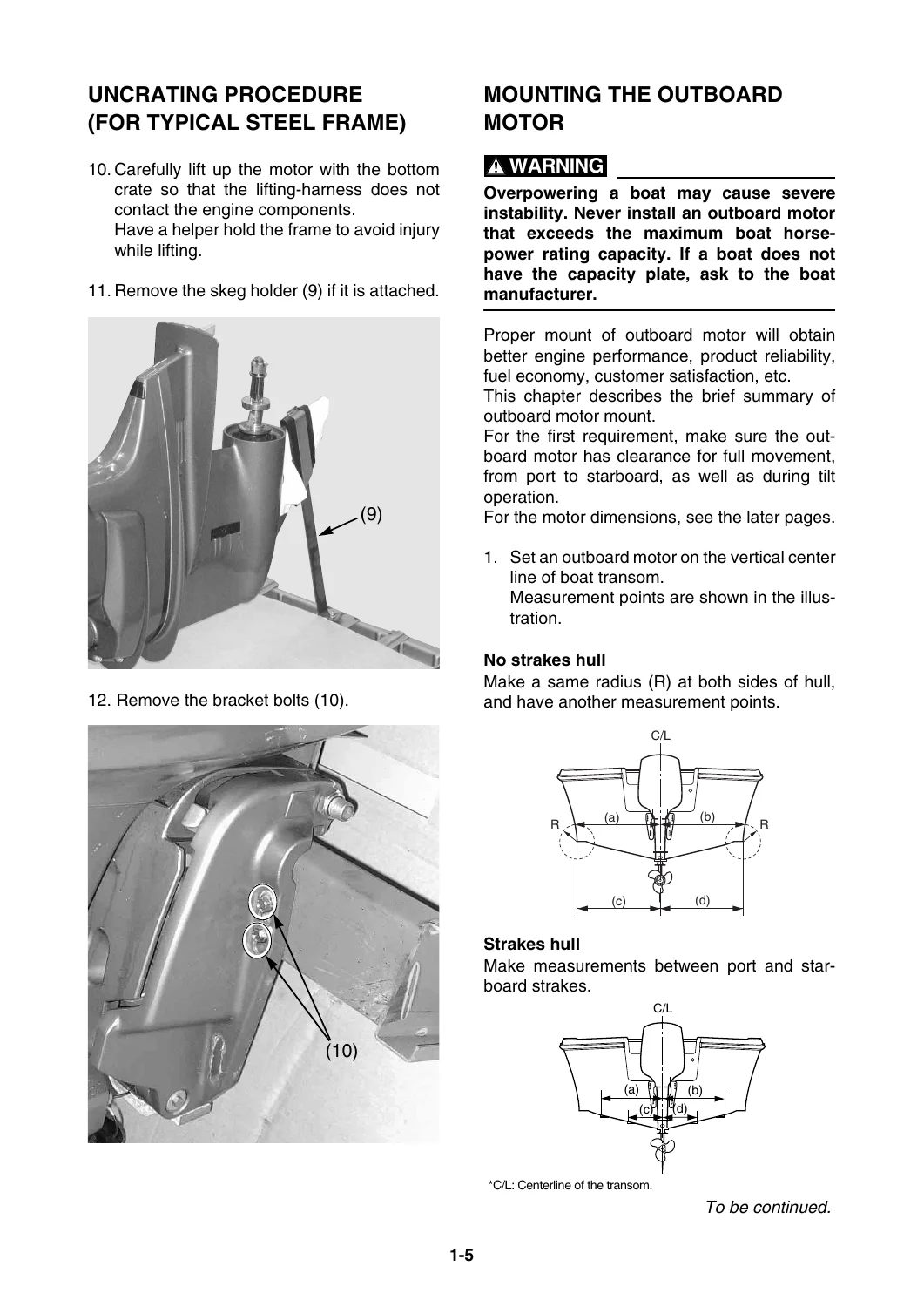
UNCRATING PROCEDURE (FOR TYPICAL STEEL FRAME)p. 11
+MOUNTING THE OUTBOARD MOTORp. 13
No strakes hullp. 13
Strakes hullp. 13
Single engine applicationp. 15
Twin engine application/Quad engine applicationp. 15
Triple engine applicationp. 15
WATER LEVEL GUIDELINE (4-STROKE ENGINES)p. 17
ADJUSTING TWIN ENGINESp. 18
MAX. BOAT SPEED ESTIMATIONp. 18
+OUTBOARD MOTOR DIMENSIONSp. 19
OVERALL DIMENSION ITEMSp. 19
OVERALL DIMENSIONS (4-STROKE)p. 21
OVERALL DIMENSIONS (2-STROKE)p. 29
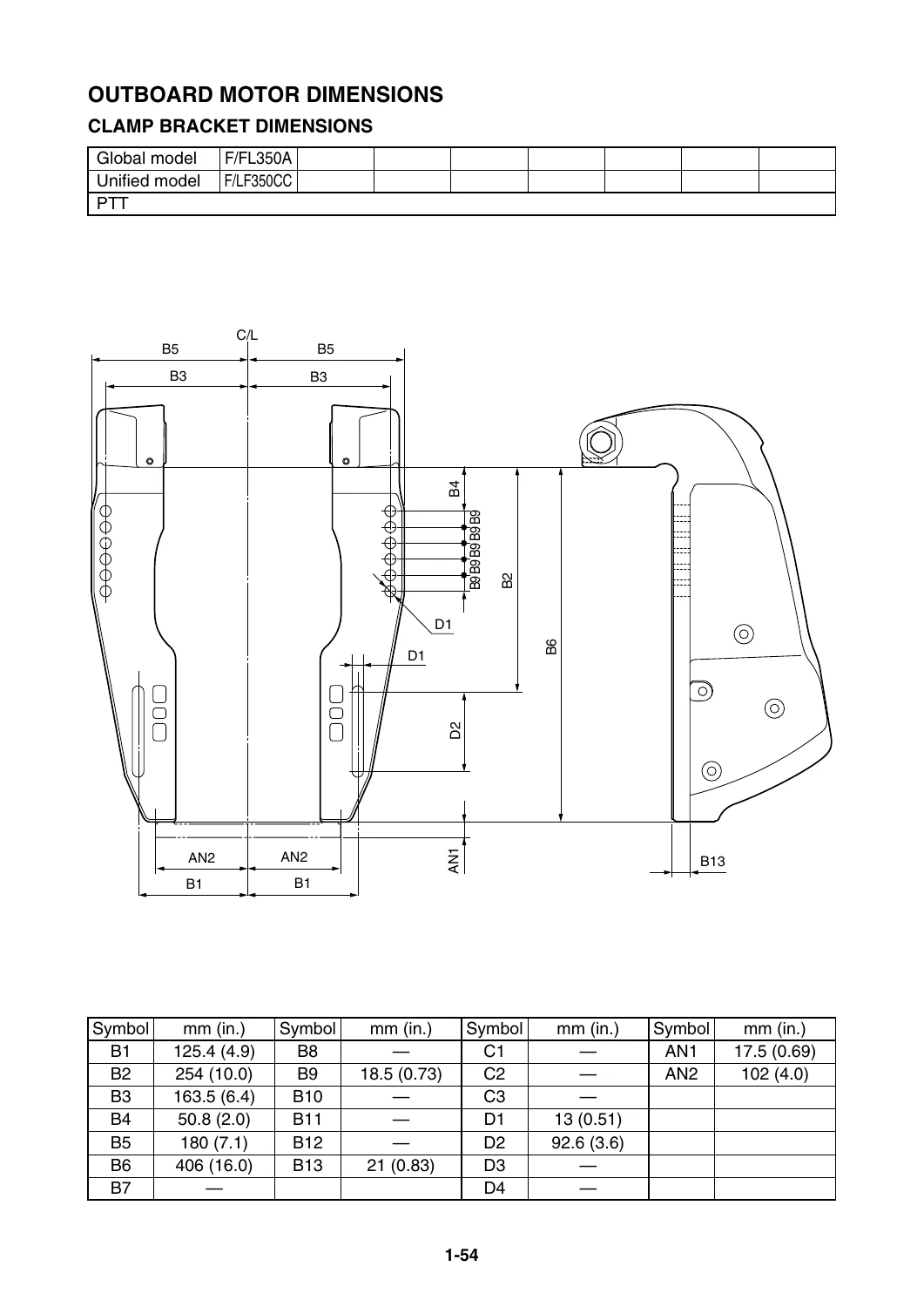
CLAMP BRACKET DIMENSION ITEMSp. 34
CLAMP BRACKET DIMENSIONSp. 35
+PROPELLERSp. 63
+PROPELLER SPECIFICATIONSp. 64
+PROPELLER TYPESp. 64
STANDARDp. 64
TALON SERIESp. 64
RELIANCE SERIESp. 64
SALTWATER SERIES IIp. 64
SALTWATER SERIES XLp. 65
SALTWATER SERIES HS4p. 65
SALTWATER SERIES XL4p. 66
VMAX SERIESp. 66
PERFORMANCEp. 66
HIGH PERFORMANCEp. 66
WEEDLESSp. 66
DUAL THRUSTp. 67
PROPELLER IDENTIFICATIONp. 67
PROPELLER SELECTIONp. 68
+2018 PROPELLER APPLICATIONSp. 68
+STANDARD PROPELLERp. 68
2 psp. 68
2 – 3 psp. 68
4 – 6 psp. 68
8 psp. 69
8 – 9.9 psp. 69
9.9 – 15 psp. 69
9.9 – 20 psp. 69
20 – 30 psp. 70
FT/T25 & 30 – 60 psp. 70
40 psp. 71
55 – 130 psp. 71
L115 psp. 71
150 – 200 psp. 72
L150 – L200 psp. 72
150 – 250 psp. 72
L150 – L250 psp. 73
200 – 250 psp. 73
L200 – L250 psp. 73
+STANDARD PROPELLER (SDS: Shift Dampener System)p. 74
150 – 250 psp. 74
L150 – L250 psp. 74
+TALON SERIES PROPELLERS (SDS: Shift Dampener System)p. 75
40 – 130 psp. 75
L115 psp. 75
+TALON 4 SERIES PROPELLERS (SDS: Shift Dampener System)p. 76
+DUAL THRUST PROPELLERSp. 77
8 – 9.9 psp. 77
8 – 9.9 psp. 77
9.9 – 15 psp. 77
20 – 30 psp. 77
25 psp. 77
50 – 70 psp. 77
+WEEDLESS PROPELLERSp. 78
4 – 6 psp. 78
20 – 30 psp. 78
+RELIANCE SERIES PROPELLERS (STD)p. 78
150 – 250 psp. 78
L150 – L250 psp. 78
+RELIANCE SERIES PROPELLERS (SDS: Shift Dampener System)p. 79
150 – 300 psp. 79
L150 – L300 psp. 79
+SALTWATER SERIES PROPELLERSp. 80
150 – 250 psp. 80
L150 – L250 psp. 80
+SALTWATER SERIES II PROPELLERS (STD)p. 81
150 – 250 psp. 81
L150 – L250 psp. 81
+SALTWATER SERIES II PROPELLERS (SDS: Shift Dampener System)p. 82
150 – 300 psp. 82
L150 – L300 psp. 82
+SALTWATER SERIES HS4 PROPELLERS (STD)p. 83
150 – 250psp. 83
L150 – L250 psp. 83
+SALTWATER SERIES HS4 PROPELLERS (SDS: Shift Dampener System)p. 83
150 – 300 psp. 83
L150 – L300 psp. 83
+SALTWATER SERIES XL PROPELLERS (SDS: Shift Dampener System)p. 84
350 ps (V8 engine)p. 84
L350 ps (V8 engine)p. 84
+SALTWATER SERIES XL4 PROPELLERS (SDS: Shift Dampener System)p. 84
350 ps (V8 engine)p. 84
L350 ps (V8 engine)p. 84
+VMAX SERIES PROPELLERSp. 85
150 – 275 ps (SHO engine)p. 85
+PERFORMANCE SERIES PROPELLERSp. 85
50 – 130 psp. 85
150 – 185 psp. 85
+HIGH PERFORMANCE SERIES PROPELLERSp. 86
WOT OPERATION RANGE TABLEp. 87
+REMOTE CONTROLSp. 89
+REMOTE CONTROL TYPES AND APPLICATIONSp. 90
703 SIDE MOUNT REMOTE CONTROLp. 91
704 BINNACLE MOUNT REMOTE CONTROLp. 93
6X3 CONCEALED REMOTE CONTROLp. 95
6X5 BINNACLE MOUNT REMOTE CONTROL (FOR US)p. 98
6X6 BINNACLE MOUNT REMOTE CONTROL [DEC]p. 100
6X7 CONCEALED REMOTE CONTROL [DEC]p. 105
+REMOTE SWITCH TYPES AND APPLICATIONSp. 107
+COMBINATION SWITCH PANEL (IG SWITCH AND EMERGENCY STOP SWITCH)p. 107
SINGLE IG SWITCH W/ PANELp. 107
SINGLE IG SWITCH W/O PANELp. 108
TWIN IG SWITCHp. 109
TRIPLE IG SWITCHp. 111
QUAD IG SWITCHp. 113
+INDEPENDENT SWITCH PANELp. 115
IG SWITCH W/ PANELp. 115
IG SWITCH W/O PANELp. 117
EMERGENCY STOP SWITCH W/ PANELp. 118
EMERGENCY STOP SWITCH W/O PANELp. 119
STATION SELECTOR SWITCHp. 120
ADAPTER FOR EMERGENCY STOP SWITCH LEADp. 121
ENGINE SHUT-OFF LANYARD (CORD)p. 121
PTT SWITCH PANELp. 121
+REMOTE CONTROL CABLESp. 122
SELECTING THE CABLE LENGTHp. 122
+REMOTE CONTROL CABLESp. 122
ROUTING THE REMOTE CONTROL CABLESp. 123
+REMOTE CONTROL THROTTLE CABLE FREE-PLAY ADJUSTMENTp. 123
PUSH-TO-OPEN TYPEp. 123
PULL-TO-OPEN TYPEp. 123
REMOTE CONTROL ATTACHMENT KITp. 124
STEERING HOOKp. 127
STEERING GUIDE ATTACHMENT KITp. 130
TIE-BAR KITp. 132
+CONVENTIONAL WIRE HARNESSp. 133
+SWITCH PANEL HARNESSp. 133
7-PIN MAIN HARNESSp. 133
10-PIN MAIN HARNESSp. 133
7- TO 10-PIN ADAPTERp. 133
+MAIN HARNESS EXTENSIONp. 133
7-PIN EXTENSION HARNESSp. 133
10-PIN EXTENSION HARNESSp. 133
+DIGITAL ELECTRONIC REMOTE CONTROL WIRE HARNESSp. 134
MAIN WIRE HARNESSp. 134
DUAL STATION WIRE-HARNESS (3-4-6P)p. 134
DUAL STATION WIRE-HARNESS (2-12P)p. 135
DUAL STATION WIRE-HARNESS (3-12P)p. 135
CONVERSION HARNESS Mp. 136
CONVERSION HARNESS Np. 136
CONVERSION HARNESS Pp. 137
+TILLER HANDLESp. 139
+6X4 MULTI-FUNCTION TILLER HANDLEp. 140
+MULTI-FUNCTION TILLER HANDLE KIT (FOR US)p. 140
TILLER HANDLE KIT CONTENTSp. 141
HANDLE FITTING KIT CONTENTSp. 142
HANDLE FITTING KIT CONTENTSp. 143
WIRING DIAGRAM (FOR US)p. 145
+EXPLODED DIAGRAM (FOR US)p. 146
+MULTI-FUNCTION TILLER HANDLE KIT (FOR JAPAN)p. 147
TILLER HANDLE KIT CONTENTSp. 147
WIRING DIAGRAM (FOR JAPAN)p. 148
+EXPLODED DIAGRAM (FOR JAPAN)p. 149
MULTI-FUNCTION TILLER HANDLE CONTENTS (FOR OTHERS)p. 150
TILLER HANDLE GROMMET DESCRIPTIONp. 150
+MULTI-FUNCTION TILLER HANDLE KIT (FOR EU & ANZ)p. 151
TILLER HANDLE KIT CONTENTSp. 151
HANDLE FITTING KIT CONTENTSp. 151
HANDLE FITTING KIT CONTENTSp. 152
HANDLE FITTING KIT CONTENTSp. 153
HANDLE IMMOBILIZER KIT CONTENTSp. 154
WIRING DIAGRAM (FOR EU & ANZ)p. 155
STEERING FRICTION CONTENTSp. 156
+CONVENTIONAL GAUGE (6Y5 & 6Y7)p. 159
+MOUNTING THE METERSp. 162
METER MOUNTING PROCEDUREp. 162
+ANALOG TACHOMETERp. 163
ANALOG TACHOMETER APPLICATIONSp. 163
ANALOG TACHOMETER DIMENSIONSp. 164
+POLE NUMBER SET UPp. 164
POLE NUMBER ADJUSTMENTp. 164
+DIGITAL TACHOMETERp. 165
DIGITAL TACHOMETER APPLICATIONSp. 165
DIGITAL TACHOMETER DIMENSIONSp. 165
+POLE NUMBER SET UPp. 166
POLE NUMBER ADJUSTMENTp. 166
+SPEEDOMETERp. 167
SPEEDOMETER TYPES AND APPLICATIONSp. 167
SPEEDOMETER DIMENSIONSp. 168
WATER PRESSURE DAMPER (OP)p. 168
SPEEDOMETER TUBE ROUTINGp. 169
DIGITAL SPEEDOMETER SET UPp. 169
+FUEL MANAGEMENT GAUGEp. 170
+FUEL MANAGEMENT GAUGE TYPES AND APPLICATIONSp. 170
FUEL MGT GAUGE KIT CONTENTSp. 170
OPTIONAL WIRE-HARNESSp. 170
FUEL MANAGEMENT GAUGE DIMENSIONSp. 171
FUEL SENSOR INSTALLATIONp. 171
+WIRING DESCRIPTIONp. 172
Connecting to 6Y5 digital speedometerp. 172
Connecting to a GPSp. 172
FUEL MANAGEMENT GAUGE SET UPp. 173
+ANALOG TRIM METERp. 174
ANALOG TRIM METER APPLICATIONSp. 174
ANALOG TRIM METER DIMENSIONSp. 174
TRIM SENSOR ADJUSTMENTp. 174
+COOLANT PRESSURE METERp. 175
+COOLANT PRESSURE METER APPLICATIONSp. 175
ADDITIONAL PARTS REQUIREMENTSp. 175
COOLANT PRESSURE METER DIMENSIONSp. 175
COOLANT PRESS. ATTACHMENT INSTALLATIONp. 175
+COOLANT TEMP. METERp. 176
+COOLANT TEMP. METER TYPES AND APPLICATIONSp. 176
ADDITIONAL PARTS REQUIREMENTSp. 176
COOLANT TEMP. METER DIMENSIONSp. 176
COOLANT PRESS. ATTACHMENT AND/OR COOLANT TEMP. SENSOR INSTALLATION (FOR 2-STROKE MODELS)p. 177
ROUTING COOLANT TEMP. LEADp. 178
ROUTING THE COOLANT PRESS. TUBEp. 178
COOLANT TEMP. SENSOR AND/OR COOLANT PRESS. ATTACHMENT INSTALLATION (FOR 4-STROKE MODELS)p. 179
ROUTING THE COOLANT TEMP. LEAD & COOLANT PRESS. TUBEp. 181
SENSOR/ATTACHMENT INSTALLATION AND ROUTINGp. 182
+HOUR METERp. 183
HOUR METER APPLICATIONSp. 183
HOUR METER DIMENSIONSp. 183
WIRING THE MECHANICAL HOUR METERp. 184
WIRING THE DIGITAL HOUR METERp. 184
+VOLTAGE METERp. 185
VOLTAGE METER TYPES AND APPLICATIONSp. 185
VOLTAGE METER DIMENSIONSp. 185
WIRING THE VOLTAGE METERp. 185
+FUEL METERp. 186
FUEL METER TYPES AND APPLICATIONSp. 186
FUEL METER DIMENSIONSp. 186
WIRING THE FUEL METERp. 186
+CHARGE WARNING UNITp. 187
+CHARGE WARNING UNIT TYPES AND APPLICATIONSp. 187
ADDITIONAL PARTS REQUIREMENTSp. 187
WIRING THE CHARGE WARNING UNITp. 187
+WIRE HARNESSESp. 188
ADDITIONAL ACCESSORY LEADp. 188
METER HARNESSp. 189
LAMP SWITCHp. 190
TRIM METER LEADp. 190
TRIM AND OIL LEADp. 190
CONVERSION HARNESS 1p. 191
FUEL MANAGEMENT GAUGE HARNESSp. 191
LIGHTING COIL EXTENSION HARNESSp. 191
RECTIFIER KITp. 191
+WIRING DIAGRAMSp. 192
WIRE COLOR CODEp. 192
+DIGITAL METER (6Y5)p. 193
SINGLE ENGINE W/ 703 RCp. 193
SINGLE ENGINE W/ 704 RCp. 194
ANALOG METER (6Y7)p. 196
+INTERCHANGEABILITY BETWEEN TACHOMETER AND ENGINE (up to 2006 and after 2007)p. 197
ANALOG TACHOMETERp. 198
DIGITAL TACHOMETERp. 199
+RIGGING GROMMET DESCRIPTIONp. 200
F80B, F90B, F100Dp. 200
F75D, F80D, F90C, F90D, F100F, F/FL115B, F130A (F75B, F90B, VF90A, F/LF115B, VF115A, F130A)p. 200
F200, F225, F250 (V6-3.3L, VCT)p. 200
F200-F300 (V6-4.2L, Mechanical RC)p. 201
F150-F200 (L4-2.8L, Mechanical RC)p. 201
F200 (L4-2.8L, DEC), F225-F300 (V6-4.2L, DEC)p. 202
F350 (V8-5.3L, DEC)p. 202
+DIGITAL NETWORK GAUGE (6YC & 6Y8)p. 203
DIGITAL NETWORK GAUGE (6YC, 6Y8) COMPATIBLE MODELSp. 204
+DIGITAL NETWORK GAUGE (6Y8)p. 204
DIGITAL NETWORK GAUGE (6YC)p. 206
+OPTIONAL EQUIPMENTp. 207
MULTI-SENSOR APPLICATIONp. 207
SPEED SENSOR KITp. 207
COOLANT PRESSURE SENSOR KITp. 208
SPEED/COOLANT PRESSURE SENSORS KITp. 208
COOLANT PRESSURE SENSOR CONNECTOR KITp. 209
NMEA2000 GATEWAYp. 209
ANALOG GAUGE INTERFACE (AGI)p. 210
+WIRE HARNESSp. 211
MAIN BUS WIREp. 211
PIGTAIL BUS WIREp. 211
SYSTEM POWER SUPPLY WIREp. 211
IMMOBILIZER POWER DISTRIBUTION WIRE 1p. 211
FUEL TANK / GPS WIREp. 212
NETWORK HUBp. 212
IMMOBILIZER UNITp. 213
+NETWORK WIRING DIAGRAMSp. 214
FUEL INJECTED F25-F250 [Mechanical RC] SINGLE ENGINE APPLICATIONp. 214
FUEL INJECTED F115-F250 [Mechanical RC] TWIN ENGINE APPLICATION (Simple)p. 215
FUEL INJECTED F115-F250 [Mechanical RC] TWIN ENGINE APPLICATION (STD)p. 216
FUEL INJECTED F115-F250 [Mechanical RC] TRIPLE ENGINE APPLICATIONp. 217
+INITIAL GAUGE SETUPp. 218
SETTING FOR GAUGE WHEN 6Y9 MULTI-SENSOR IS CONNECTEDp. 219
TROUBLESHOOTINGp. 221
BASIC REQUIREMENTSp. 222
NMEA0183 COMPATIBLE EQUIPMENT CONNECTIONp. 222
DIGITAL NETWORK GAUGE (6YC, 6Y8) FUNCTION TABLEp. 223
+CL7 DISPLAY (6YD)p. 225
CL7 DISPLAYp. 227
+OPTIONAL EQUIPMENTp. 230
TRANSOM MULTI-SENSOR (6Y9)p. 230
IMMOBILIZER UNITp. 230
NMEA2000 GATEWAYp. 231
ANALOG GAUGE INTERFACE (AGI)p. 232
SPEED SENSOR KITp. 233
COOLANT PRESSURE SENSOR KITp. 233
NETWORK HUBp. 234
+WIRE HARNESSp. 235
MAIN BUS WIREp. 235
PIGTAIL BUS WIREp. 235
WIRE LEAD FOR CL7 DISPLAYp. 235
TANK WIREp. 235
SYSTEM POWER SUPPLY WIREp. 236
SYSTEM POWER DISTRIBUTION WIREp. 236
IMMOBILIZER POWER DISTRIBUTION WIRE 2p. 236
CONVERSION HARNESSp. 237
CONVERSION HARNESS 1p. 237
CONVERSION HARNESS 6p. 237
CONVERSION HARNESS M (FOR 2ND HELM)p. 238
CONVERSION HARNESS N (FOR 2ND HELM)p. 238
CONVERSION HARNESS P (FOR 2ND HELM)p. 238
CONVERSION HARNESS K (FOR DUAL STATION)p. 238
+NETWORK WIRING DIAGRAMSp. 240
SINGLE STATION W/ CL7 DISPLAY SINGLE ENGINE APPLICATION (6X6 binnacle mount Digital Electronic Control)p. 240
SINGLE STATION W/ 6YC GAUGE SINGLE ENGINE APPLICATION (6X6 binnacle mount Digital Electronic Control)p. 242
SINGLE STATION W/ CL7 DISPLAY SINGLE ENGINE APPLICATION (6X7 concealed Digital Electronic Control)p. 244
SINGLE STATION W/ 6YC GAUGE SINGLE ENGINE APPLICATION (6X7 concealed Digital Electronic Control)p. 246
SINGLE STATION W/ CL7 DISPLAY TWIN ENGINE APPLICATIONp. 248
SINGLE STATION W/ 6YC GAUGE TWIN ENGINE APPLICATIONp. 250
SINGLE STATION W/ CL7 DISPLAY TRIPLE ENGINE APPLICATIONp. 252
SINGLE STATION W/ CL7 DISPLAY QUAD ENGINE APPLICATION (FOR F/LF225CA, F/LF250CA, F/LF300CA, F/LF350CA/B/C)p. 254
DUAL STATION W/ CL7 DISPLAY SINGLE ENGINE APPLICATIONp. 258
DUAL STATION W/ 6YC GAUGE SINGLE ENGINE APPLICATIONp. 260
DUAL STATION W/ CL7 DISPLAY TWIN ENGINE APPLICATIONp. 262
DUAL STATION W/ 6YC GAUGE TWIN ENGINE APPLICATIONp. 264
DUAL STATION W/ CL7 DISPLAY TRIPLE ENGINE APPLICATIONp. 266
DUAL STATION W/ CL7 DISPLAY QUAD ENGINE APPLICATION (FOR F/LF225CA, F/LF250CA, F/LF300CA, F/LF350CA/B/C)p. 268
+BATTERYp. 271
RECOMMENDED BATTERYp. 272
BATTERY CABLE LENGTHp. 274
+BATTERY WIRINGp. 275
ISOLATOR EQUIPPED MODELSp. 275
EXAMPLE FOR BATTERY CABLE WIRING (TWIN ENGINE APPLICATION)p. 276
RECOMMENDED EXTENSION LENGTH OF BATTERY CABLESp. 277
RECOMMENDED BATTERY SWITCH CAPACITYp. 281
BATTERY CHARGING CAPABILITYp. 281
+APPENDIXp. 283
+MODEL NAME DESIGNATIONp. 285
GLOBAL MODELS IDENTIFICATIONp. 285
UNIFIED MODELS IDENTIFICATIONp. 286
+FUEL SYSTEM VACUUM PRESSURE STANDARDp. 287
FUEL HOSE ROUTING RESISTANCE MEASURING METHODp. 287
LOWEST VACUUM PRESSURE STANDARDp. 288
PORTABLE FUEL TANKS (TYPICAL)p. 289
FUEL PIPES (TYPICAL)p. 290
PRIMARY PUMP (TYPICAL)p. 290
PRE-DELIVERY INSPECTION (PDI)p. 291
+CONVENTIONAL RIGGING KIT CONTENTSp. 292
DIGITAL TACHOMETER KITp. 292
DIGITAL TACHOMETER AND SPEEDOMETER KITp. 292
TWIN-MOTOR KITp. 293
+DIGITAL NETWORK GAUGE RIGGING KIT CONTENTSp. 294
+6YC GAUGE RIGGING KIT (FOR EU)p. 294
SINGLE KIT (Mechanical RC) w/o Speed Sensor Kitp. 294
TWIN KIT (Mechanical RC) w/o Speed Sensor Kitp. 294
SINGLE ENGINE GAUGE KIT (DEC)p. 295
TWIN ENGINE GAUGE KIT (DEC)p. 295
+6YC GAUGE RIGGING KITp. 296
SINGLE KIT (Mechanical RC)p. 296
SINGLE KIT (DEC)p. 296
TWIN KIT (Mechanical RC)p. 297
TWIN KIT (DEC)p. 298
+6YC GAUGE RIGGING KIT (FOR ANZ)p. 299
TWIN KIT (Mechanical RC)p. 299
+6YC GAUGE RIGGING KIT (FOR JPN)p. 299
SINGLE KIT (Mechanical RC)p. 299
SINGLE KIT (DEC)p. 300
TWIN KIT (DEC)p. 300
+6Y8 GAUGE RIGGING KIT (FOR EU)p. 301
SINGLE KIT 1 (TACH)p. 301
SINGLE KIT 2 (TACH, SPEED/FUEL) w/o Speed Sensor Kitp. 301
+6Y8 GAUGE RIGGING KITp. 302
SINGLE KIT 2 (TACH, SPEED/FUEL)p. 302
+6Y8 GAUGE RIGGING KIT (FOR JPN)p. 302
SINGLE KIT 1 (TACH)p. 302
SINGLE KIT 2 (TACH, SPEED/FUEL)p. 302
+IMMOBILIZER RIGGING KIT CONTENTSp. 303
IMMOBILIZER KIT 1 (FOR US, ANZ, CRB*)p. 303
IMMOBILIZER KIT 2 (FOR JPN)p. 303
IMMOBILIZER KIT 3 (FOR EU)p. 303
+DIGITAL NETWORK PREMIUM GAUGE RIGGING KIT CONTENTSp. 304
SINGLE ENGINE PREMIUM GAUGE KITp. 304
ADDITIONAL PREMIUM GAUGE KIT (EU, ANZ, GEN)p. 304
TWIN ENGINE PREMIUM GAUGE KITp. 305
TRIPLE ENGINE PREMIUM GAUGE KIT (FOR EU, ANZ, GEN)p. 305
MAIN HELM SW PANEL TWIN ENGINE KIT (FOR NOA)p. 305
MAIN HELM SW PANEL TRIPLE ENGINE KIT (FOR NOA)p. 306
2ND HELM SW PANEL SINGLE ENGINE KIT (FOR NOA)p. 306
2ND HELM SW PANEL TWIN ENGINE KIT (FOR NOA)p. 306
2ND HELM SW PANEL TRIPLE ENGINE KIT (FOR NOA)p. 306
+OTHER RIGGING KIT CONTENTSp. 307
TILT LIMIT SWITCH KIT (FOR NOA, EU, ANZ, RUS, JPN)p. 307
TILT LIMIT SWITCH KIT 2 (FOR NOA, EU, ANZ, JPN, RUS, TUR)p. 307
TILT LIMIT SWITCH KIT 3 (FOR NOA, EU, ANZ, JPN, RUS, TUR)p. 308
TILT LIMIT SWITCH KIT 4 (FOR NOA, EU, ANZ, JPN, RUS, TUR)p. 308
LIGHTING COIL KIT (FOR EU, CA, JPN)p. 309
CL7 DISPLAY Installation Instructionsp. 310
+2018 YEAR MODELS MANUFACTURE STARTING SERIAL NUMBERSp. 314
4-STROKE ENGINESp. 314
2-STROKE ENGINESp. 317
Transom Mounting and Structural Engineering
Correct engine mounting is paramount to vessel stability, hydrodynamic efficiency, and powerhead longevity. The 2018 Yamaha Outboard Rigging Guide Worldwide Edition delivers precise engineering requirements for boat transom centerlines, anti-cavitation plate height placement (0 to 25 mm below hull bottom for standard hulls; flush or elevated for high-performance planing craft), and transom bolt torque values (M8: 18 Nm; M10: 36 Nm; M12: 52 Nm). It contains specialized transom thickness bolt selection charts from 55 mm to over 115 mm, stern-heavy water level guidelines (minimum clamp bracket seating height H) to prevent water ingestion on 4-stroke conversions, and multi-engine spacing recommendations (T1 centerline-to-centerline dimensions) for twin, triple, and quad installations.
Mechanical Controls, DEC Systems, and Advanced Networking
Whether rigging conventional push-to-open or pull-to-open mechanical control boxes (703, 704, 6X3) or installing drive-by-wire Digital Electronic Controls (6X6 binnacle, 6X7 concealed), this manual outlines every critical adjustment. Detailed schematics walk through 10-pin and 16-pin main harness routing, dual-station conversion harnesses (M, N, P, K), engine synchronization modules, and the digital network architectures powering Command Link (6Y8), 6YC color displays, and the advanced 6YD CL7 7-inch touchscreen ecosystem.
Professional Capability and Instant Delivery
Equipped with the 2018 Yamaha Outboard Rigging Guide Worldwide Edition, technicians, boatbuilders, and marine service professionals can confidently tackle complete vessel repowers, multi-helm steering and throttle setups, digital network hub expansions, propeller pitch optimization, and electrical diagnostic integrations. Working with exact factory tolerances, wiring color codes, and torque specifications ensures compliance with manufacturer standards and eliminates costly rigging errors. Available as an instant high-resolution PDF download, this digital reference provides immediate access on any computer, tablet, or smartphone, with full print capability for shop or dockside use.


Reviews
There are no reviews yet.