★ TRUSTED BY 321,897+ PROFESSIONALS WORLDWIDE
🏢
Trusted Business
Verified & Licensed
🛡️
Virus Free Files
100% Safe Downloads
🔒
Secure Payment
SSL Protected
⚡
Instant Delivery
Available Immediately
Sale!

2020-2021 Husqvarna TE 250i TE 300i Repair Manual – Complete Workshop PDF

Original price was: $39.95.Current price is: $24.95.

Full Husqvarna repair manual for 2020-2021 TE 250i and TE 300i models. Engine, fuel injection, WP suspension, brakes, wiring diagrams and complete specifications for EU, US and Rockstar Edition.

⚡
Instant PDF Download
Available immediately
💾
Save to Your Device
Download & keep forever
🛡️
Antivirus Scanned
100% virus-free
🌍
Trusted Worldwide
175,000+ customers

Description

2020-2021 Husqvarna TE 250i TE 300i Repair Manual

This 2020-2021 Husqvarna TE 250i TE 300i Repair Manual is the complete workshop-level service guide for Husqvarna’s fuel-injected two-stroke enduro platform. It covers the TE 250i EU and TE 250i US, the TE 300i EU and TE 300i US, plus the TE 300i Rockstar Edition EU and TE 300i Rockstar Edition US in full. Whether you are rebuilding a top end, chasing an electrical fault, servicing the WP XPLOR fork, or simply setting chain tension and checking torque values, the procedures here are written for the technician working on the bike in front of them.

File Details

  • Manual type: Repair Manual / Workshop Manual
  • Brand: Husqvarna Motorcycles
  • Model: TE 250i, TE 300i (EU, US and Rockstar Edition)
  • Model year coverage: 2020 / 2021
  • Language: English
  • File format: PDF
  • Page count: 379 pages
  • Document organisation: 36 numbered chapters plus index, wiring diagram section and special tools

Chapters Covered

  • Means of Representation, Safety Advice, Important Notes
  • Serial Numbers – VIN, type label, engine number, fork and shock absorber article numbers
  • Motorcycle – lifting, starting, function checks
  • Fork, Triple Clamp – compression, rebound, spring preload, bleeding, full fork disassembly and reassembly, cartridge and tap compression servicing, steering head bearing
  • Handlebar, Controls – handlebar position, clutch lever, throttle cable routing and play, grip replacement, throttle response map
  • Frame – engine guard, frame inspection, footrest replacement
  • Shock Absorber, Link Fork – high/low speed compression, rebound, spring preload, static and riding sag, full damper disassembly and rebuild, link fork bearings
  • Exhaust System – main silencer, manifold, glass fibre yarn filling
  • Air Filter – removal, installation, cleaning of filter and box
  • Fuel Tank, Seat, Trim – filler cap, side cover, seat, fuel tank removal/install, fuel pressure test, fuel screen, fuel filter, fuel pump
  • Mask, Fender – front fender, headlight mask
  • Wheels – tire pressure, tire condition, wheel bearings, brake discs, spoke tension, rim run-out, front and rear wheel removal/install, wheel bearing replacement, chain inspection and adjustment, drivetrain kit
  • Wiring Harness, Battery – ignition curve connector, main fuse, individual fuses, 12-V battery removal/install/charging, charging voltage, open-circuit current, starter relay, diagnostics connector
  • Brake System – front and rear brake linings, brake fluid level and change, hand brake lever, foot brake lever free travel and basic position
  • Lighting System, Instruments – combination instrument setup, km/miles, clock, wheel circumference, service display, headlight bulb, turn signal bulb, headlight setting
  • Engine – pressure sensor hose and connections, engine removal/install, full engine disassembly and assembly, crankshaft, cylinder, piston, clutch, transmission, shift mechanism, balancer shaft, water pump, exhaust control, X-distance and Z-distance adjustment
  • Clutch – hydraulic clutch fluid level and change, clutch inspection and rebuild
  • Water Pump, Cooling System – antifreeze, coolant level, draining, refilling, changing coolant, coolant pipe replacement
  • Exhaust Control – basic setting check and adjustment
  • Lubrication System – gear oil change and level, 2-stroke oil level, oil pump priming, oil pump change, oil screen cleaning
  • Ignition System – ignition system check, ignition coil primary winding, spark plug connector, alternator stator, crankshaft speed sensor, spark plug
  • Electric Starter System – starter motor check
  • Throttle Valve Body – idle speed, ambient air pressure programming, cold start button
  • Technical Data – engine, tolerance and wear limits, tightening torques, capacities, chassis, electrical system, tires, fork, shock absorber
  • Cleaning, Care, Storage, Service Schedule
  • Wiring Diagram – complete 8-page EU diagram and 6-page US diagram
  • Substances, Auxiliary Substances, Special Tools, Standards, Glossary, Abbreviations, Index

What this document gives a technician is a single, coherent reference for the entire machine. The engine chapter alone runs through splitting the cases, removing the crankshaft, checking the cylinder bore across the X and Y axes, measuring piston-to-cylinder clearance, inspecting the reed valve housing, reassembling the transmission shafts, and setting the exhaust control Z-distance. The chassis and suspension chapters provide the same level of procedural depth for the WP XPLOR fork and WP XACT shock absorber, including full damper bleeding and nitrogen filling. The wiring diagram section is split by model market so the correct harness layout is available for both EU and US machines.

Why This Manual Matters for 2020-2021 TE 250i and TE 300i Owners

Modern fuel-injected two-strokes are not the simple carbureted machines of the past. The TE 250i and TE 300i run transfer duct injection, an electronic oil pump, a crankshaft speed sensor, a throttle valve position sensor and a pressurised fuel system. Guessing at diagnostics or torque values on these systems is expensive. This Husqvarna TE 250i TE 300i repair manual provides the exact tightening torques, wear limits, clearances and adjustment values for the 2020-2021 models, so engine, suspension and brake work is done to specification rather than to feel.

For the home mechanic, the value is in the detail: the X-distance and Z-distance adjustment procedures, the clutch stack measurement, the fork cartridge assembly steps, the fuel pressure test values and the wiring diagram by model market are all included. For the professional workshop, it is a complete reference that covers both the standard TE models and the Rockstar Edition without needing separate documentation.

Complete PDF Bookmark Tree

Complete Bookmarks

The complete bookmarks in the “2020-2021 Husqvarna TE 250i TE 300i Repair Manual – Complete Workshop PDF” are as follows:

1 MEANS OF REPRESENTATIONp. 9
1.1 Symbols usedp. 9
1.2 Formats usedp. 9
2 SAFETY ADVICEp. 10
2.1 Repair Manualp. 10
2.2 Safety advicep. 10
2.3 Degrees of risk and symbolsp. 10
2.4 Work rulesp. 10
3 IMPORTANT NOTESp. 11
3.1 Manufacturer warranty, implied warrantyp. 11
3.2 Fuel, auxiliary substancesp. 11
3.3 Spare parts, accessoriesp. 11
3.4 Figuresp. 11
4 SERIAL NUMBERSp. 12
4.1 Vehicle identification numberp. 12
4.2 Type label (All EU models)p. 12
4.3 Engine numberp. 12
4.4 Fork article numberp. 12
4.5 Shock absorber article numberp. 13
5 MOTORCYCLEp. 14
5.1 Raising the motorcycle with a lift standp. 14
5.2 Removing the motorcycle from the lift standp. 14
5.3 Starting the vehiclep. 14
5.4 Starting the motorcycle to check the functionp. 15
6 FORK, TRIPLE CLAMPp. 16
6.1 Adjusting the compression damping of the forkp. 16
6.2 Adjusting the rebound damping of the forkp. 16
6.3 Adjusting the spring preload of the forkp. 17
6.4 Bleeding the fork legsp. 17
6.5 Cleaning the dust boots of the fork legsp. 18
6.6 Removing the fork protectorp. 19
6.7 Installing the fork protectorp. 19
6.8 Removing the fork legsp. 19
6.9 Installing the fork legsp. 20
6.10 Servicing the forkp. 21
6.11 Disassembling the fork legsp. 21
6.12 Disassembling the cartridgep. 24
6.13 Disassembling the tap compressionp. 27
6.14 Checking the fork legsp. 28
6.15 Assembling the tap compressionp. 29
6.16 Assembling the cartridgep. 30
6.17 Assembling the fork legsp. 33
6.18 Greasing the steering head bearingp. 38
6.19 Removing the lower triple clampp. 39
6.20 Installing the lower triple clampp. 40
6.21 Checking steering head bearing playp. 42
6.22 Changing the steering head bearingp. 42
6.23 Adjusting steering head bearing playp. 44
7 HANDLEBAR, CONTROLSp. 45
7.1 Handlebar positionp. 45
7.2 Adjusting the handlebar positionp. 45
7.3 Adjusting the basic position of the clutch leverp. 46
7.4 Checking the throttle cable routingp. 46
7.5 Checking the play in the throttle cablep. 47
7.6 Adjusting the play in the throttle cablep. 47
7.7 Checking the rubber gripp. 48
7.8 Setting the characteristic map of the throttle responsep. 48
8 FRAMEp. 50
8.1 Removing the engine guardp. 50
8.2 Installing the engine guardp. 50
8.3 Checking the framep. 50
8.4 Changing the footrestsp. 50
9 SHOCK ABSORBER, LINK FORKp. 54
9.1 Adjusting the high-speed compression damping of the shock absorberp. 54
9.2 Adjusting the low-speed compression damping of the shock absorberp. 54
9.3 Adjusting the rebound damping of the shock absorberp. 55
9.4 Measuring the dimension of the rear wheel unloadedp. 56
9.5 Checking the static sag of the shock absorberp. 56
9.6 Checking the riding sag of the shock absorberp. 57
9.7 Adjusting the spring preload of the shock absorberp. 57
9.8 Adjusting the riding sagp. 58
9.9 Removing the shock absorberp. 59
9.10 Installing the shock absorberp. 61
9.11 Checking the shock absorber linkagep. 62
9.12 Servicing the shock absorberp. 64
9.13 Removing the springp. 65
9.14 Disassembling the damperp. 66
9.15 Disassembling the piston rodp. 67
9.16 Disassembling the seal ring retainerp. 68
9.17 Changing the pilot bushingp. 69
9.18 Checking the damperp. 70
9.19 Changing the heim jointp. 71
9.20 Assembling the seal ring retainerp. 72
9.21 Assembling the piston rodp. 73
9.22 Assembling the damperp. 75
9.23 Bleeding and filling the damperp. 77
9.24 Filling damper with nitrogenp. 80
9.25 Installing the springp. 81
9.26 Checking the link forkp. 82
9.27 Checking the fork bearing for playp. 82
9.28 Removing the link forkp. 83
9.29 Installing the link forkp. 85
9.30 Changing the link fork bearingp. 87
9.31 Checking the shock absorber heim joint for playp. 89
10 EXHAUST SYSTEMp. 91
10.1 Removing the main silencerp. 91
10.2 Installing the main silencerp. 91
10.3 Removing the manifoldp. 91
10.4 Installing the manifoldp. 93
10.5 Changing the glass fiber yarn filling of the main silencerp. 95
11 AIR FILTERp. 96
11.1 Removing the air filter box coverp. 96
11.2 Installing the air filter box coverp. 96
11.3 Removing the air filterp. 96
11.4 Installing the air filterp. 97
11.5 Cleaning the air filter and air filter boxp. 97
12 FUEL TANK, SEAT, TRIMp. 99
12.1 Opening fuel tank filler capp. 99
12.2 Closing the fuel tank filler capp. 99
12.3 Removing the right side coverp. 100
12.4 Installing the right side coverp. 100
12.5 Removing the seatp. 100
12.6 Mounting the seatp. 101
12.7 Removing the fuel tankp. 102
12.8 Installing the fuel tankp. 103
12.9 Checking the fuel pressurep. 105
12.10 Changing the fuel screenp. 106
12.11 Changing the fuel filterp. 107
12.12 Changing the fuel pumpp. 111
13 MASK, FENDERp. 114
13.1 Removing front fenderp. 114
13.2 Installing front fenderp. 114
13.3 Removing the headlight mask with the headlightp. 115
13.4 Installing the headlight mask with the headlightp. 115
14 WHEELSp. 117
14.1 Checking tire pressurep. 117
14.2 Checking the tire conditionp. 117
14.3 Checking the wheel bearing for playp. 118
14.4 Checking the brake discsp. 119
14.5 Checking spoke tensionp. 119
14.6 Checking the rim run-outp. 120
14.7 Front wheelp. 121
14.7.1 Removing the front wheelp. 121
14.7.2 Installing the front wheelp. 122
14.7.3 Changing the front brake discp. 123
14.7.4 Changing the front wheel bearingp. 123
14.8 Rear wheelp. 125
14.8.1 Removing the rear wheelp. 125
14.8.2 Installing the rear wheelp. 126
14.8.3 Changing the rear brake discp. 127
14.8.4 Checking the chain for dirtp. 127
14.8.5 Cleaning the chainp. 127
14.8.6 Checking the chain tensionp. 128
14.8.7 Checking the chain, rear sprocket, engine sprocket, and chain guidep. 129
14.8.8 Adjusting the chain tensionp. 131
14.8.9 Changing the drivetrain kitp. 132
14.8.10 Changing the rear wheel bearingp. 134
15 WIRING HARNESS, BATTERYp. 137
15.1 Ignition curve plug-in connectorp. 137
15.2 Changing main fusep. 137
15.3 Changing the fuses of individual electrical power consumersp. 138
15.4 Disconnecting the negative cable of the 12-V batteryp. 140
15.5 Connecting the negative cable of the 12-V batteryp. 140
15.6 Removing the 12-V batteryp. 140
15.7 Installing the 12-V batteryp. 142
15.8 Charging the 12-V batteryp. 144
15.9 Checking the charging voltagep. 145
15.10 Checking the open-circuit currentp. 146
15.11 Checking the starter relayp. 146
15.12 Diagnostics connectorp. 147
16 BRAKE SYSTEMp. 148
16.1 Checking the front brake liningsp. 148
16.2 Changing the brake linings of the front brakep. 148
16.3 Adjusting the basic position of the hand brake leverp. 150
16.4 Checking the front brake fluid levelp. 151
16.5 Adding front brake fluidp. 151
16.6 Changing the front brake fluidp. 153
16.7 Checking the brake linings of the rear brakep. 155
16.8 Changing the rear brake liningsp. 155
16.9 Checking the free travel of the foot brake leverp. 158
16.10 Adjusting the basic position of the foot brake leverp. 158
16.11 Checking the rear brake fluid levelp. 159
16.12 Adding rear brake fluidp. 159
16.13 Changing the rear brake fluidp. 160
17 LIGHTING SYSTEM, INSTRUMENTSp. 163
17.1 Adjusting the combination instrumentp. 163
17.2 Setting the kilometers or milesp. 164
17.3 Setting the clockp. 164
17.4 Adjusting the wheel circumferencep. 165
17.5 Setting the service displayp. 165
17.6 Changing the headlight bulbp. 166
17.7 Changing the turn signal bulb (All EU models)p. 167
17.8 Checking the headlight settingp. 167
17.9 Adjusting the headlight rangep. 168
17.10 Changing the combination instrument batteryp. 168
17.11 Activationp. 169
18 ENGINEp. 170
18.1 Cleaning the pressure sensor hosep. 170
18.2 Cleaning the protection cap of the pressure sensorp. 170
18.3 Cleaning the hose connections of the pressure sensorp. 171
18.4 Removing the enginep. 172
18.5 Installing the enginep. 177
18.6 Engine disassemblyp. 183
18.6.1 Clamping engine into the engine work standp. 183
18.6.2 Removing the shift leverp. 184
18.6.3 Removing the clutch push rodp. 184
18.6.4 Draining the gear oilp. 184
18.6.5 Removing the spacerp. 184
18.6.6 Removing the alternator coverp. 185
18.6.7 Removing injection valvesp. 185
18.6.8 Removing the cylinder headp. 186
18.6.9 Removing the cylinderp. 186
18.6.10 Removing the pistonp. 188
18.6.11 Removing the water pump coverp. 189
18.6.12 Removing the clutch coverp. 189
18.6.13 Removing the clutch discsp. 190
18.6.14 Removing the clutch basketp. 191
18.6.15 Removing the balancer shaftp. 192
18.6.16 Removing the shift shaftp. 193
18.6.17 Removing the shift drum locating unitp. 193
18.6.18 Removing the locking leverp. 194
18.6.19 Removing the rotorp. 194
18.6.20 Removing the starter motorp. 195
18.6.21 Removing the reed valve housingp. 196
18.6.22 Removing the left section of the engine casep. 196
18.6.23 Removing the shift railsp. 196
18.6.24 Removing the shift drump. 197
18.6.25 Removing the shift forksp. 197
18.6.26 Removing the transmission shaftsp. 197
18.6.27 Removing the crankshaftp. 198
18.7 Working on individual partsp. 199
18.7.1 Working on the right section of the engine casep. 199
18.7.2 Working on the left section of the engine casep. 200
18.7.3 Removing the crankshaft bearing inner racep. 201
18.7.4 Installing the crankshaft bearing inner racep. 202
18.7.5 Changing the connecting rod, conrod bearing, and crank pinp. 202
18.7.6 Checking the crankshaft run-out at the bearing pinp. 204
18.7.7 Checking/measuring the cylinderp. 204
18.7.8 Cleaning the pressure sensor cylinder connectionp. 205
18.7.9 Removing the exhaust controlp. 205
18.7.10 Checking the exhaust controlp. 209
18.7.11 Installing the exhaust controlp. 211
18.7.12 Cylinder – Nikasil® coatingp. 218
18.7.13 Checking/measuring the pistonp. 218
18.7.14 Checking the piston ringp. 219
18.7.15 Measuring the piston/cylinder mounting clearancep. 220
18.7.16 Disassemble the reed valve housingp. 220
18.7.17 Checking the reed valve housing, reed valve and intake flangep. 221
18.7.18 Assembling the reed valve housingp. 222
18.7.19 Working on the clutch coverp. 223
18.7.20 Checking the clutchp. 226
18.7.21 Preassembling shift shaftp. 227
18.7.22 Checking the shift mechanismp. 228
18.7.23 Disassembling the main shaftp. 229
18.7.24 Disassembling the countershaftp. 230
18.7.25 Checking the transmissionp. 230
18.7.26 Assembling the main shaftp. 232
18.7.27 Assembling the countershaftp. 232
18.7.28 Checking the electric starter drivep. 233
18.8 Engine assemblyp. 234
18.8.1 Installing the crankshaftp. 234
18.8.2 Installing the transmission shaftsp. 235
18.8.3 Installing the shift forksp. 235
18.8.4 Installing the shift drump. 236
18.8.5 Installing the shift railsp. 236
18.8.6 Installing the left section of the engine casep. 236
18.8.7 Installing the reed valve housingp. 237
18.8.8 Installing the starter motorp. 238
18.8.9 Installing the rotorp. 239
18.8.10 Installing the locking leverp. 239
18.8.11 Installing the shift drum locating unitp. 240
18.8.12 Installing the shift shaftp. 240
18.8.13 Installing the balancer shaftp. 240
18.8.14 Installing the clutch basketp. 241
18.8.15 Installing the clutch discsp. 242
18.8.16 Installing the clutch coverp. 245
18.8.17 Installing the water pump coverp. 246
18.8.18 Installing the pistonp. 246
18.8.19 Installing the cylinderp. 248
18.8.20 Checking the X-distancep. 250
18.8.21 Adjusting the X-distancep. 251
18.8.22 Adjusting the Z-distancep. 252
18.8.23 Installing the cylinder headp. 255
18.8.24 Installing injection valvesp. 256
18.8.25 Installing the alternator coverp. 256
18.8.26 Installing the spacerp. 256
18.8.27 Gear oil drain plug, installingp. 257
18.8.28 Installing the clutch push rodp. 257
18.8.29 Installing the shift leverp. 257
18.8.30 Removing the engine from the engine work standp. 258
19 CLUTCHp. 259
19.1 Checking/correcting the fluid level of the hydraulic clutchp. 259
19.2 Changing the hydraulic clutch fluidp. 260
19.3 Checking the clutchp. 261
20 WATER PUMP, COOLING SYSTEMp. 270
20.1 Cooling systemp. 270
20.2 Checking the antifreeze and coolant levelp. 270
20.3 Checking the coolant levelp. 271
20.4 Draining the coolantp. 271
20.5 Refilling with coolantp. 272
20.6 Changing the coolantp. 274
20.7 Changing the coolant pipep. 275
21 EXHAUST CONTROLp. 280
21.1 Checking/adjusting the basic setting of the exhaust controlp. 280
22 LUBRICATION SYSTEMp. 281
22.1 Changing the gear oilp. 281
22.2 Checking the gear oil levelp. 282
22.3 Adding the gear oilp. 282
22.4 Checking 2-stroke oil levelp. 283
22.5 Opening 2-stroke oil tank capp. 283
22.6 Closing 2-stroke oil tank capp. 284
22.7 Adding 2-stroke oilp. 284
22.8 Priming oil pumpp. 284
22.9 Changing the oil pump, cleaning the oil screenp. 286
22.10 Cleaning the oil screen in the oil tankp. 290
23 IGNITION SYSTEMp. 293
23.1 Checking the ignition systemp. 293
23.2 Ignition coil – checking the primary windingp. 294
23.3 Checking the spark plug connectorp. 295
23.4 Alternator – checking the stator windingp. 295
23.5 Checking the crankshaft speed sensorp. 296
23.6 Changing the spark plugp. 297
23.7 Changing the spark plug and spark plug connectorp. 298
23.8 Removing the statorp. 299
23.9 Installing the statorp. 299
24 ELECTRIC STARTER SYSTEMp. 300
24.1 Checking the starter motorp. 300
25 THROTTLE VALVE BODYp. 301
25.1 Adjusting the idle speedp. 301
25.2 Programming ambient air pressurep. 301
25.3 Cold start buttonp. 302
26 TECHNICAL DATAp. 303
26.1 Enginep. 303
26.1.1 All TE 250i modelsp. 303
26.1.2 All TE 300i modelsp. 303
26.2 Tolerance, engine wear limitsp. 304
26.2.1 All TE 250i modelsp. 304
26.2.2 All TE 300i modelsp. 305
26.3 Engine tightening torquesp. 305
26.4 Capacitiesp. 307
26.4.1 Gear oilp. 307
26.4.2 Engine oilp. 307
26.4.3 Coolantp. 307
26.4.4 Fuelp. 307
26.5 Chassisp. 307
26.6 Electrical systemp. 308
26.7 Tiresp. 308
26.8 Forkp. 309
26.9 Shock absorberp. 309
26.10 Chassis tightening torquesp. 310
27 CLEANING, CAREp. 312
27.1 Cleaning the motorcyclep. 312
27.2 Checks and maintenance steps for winter operationp. 313
28 STORAGEp. 314
28.1 Storagep. 314
28.2 Preparing for use after storagep. 315
29 SERVICE SCHEDULEp. 316
29.1 Additional informationp. 316
29.2 Required workp. 316
29.3 Recommended workp. 317
30 WIRING DIAGRAMp. 320
30.1 Page 1 of 8 (All EU models)p. 320
30.2 Page 2 of 8 (All EU models)p. 322
30.3 Page 3 of 8 (All EU models)p. 324
30.4 Page 4 of 8 (All EU models)p. 326
30.5 Page 5 of 8 (All EU models)p. 328
30.6 Page 6 of 8 (All EU models)p. 330
30.7 Page 7 of 8 (All EU models)p. 332
30.8 Page 8 of 8 (All EU models)p. 334
30.9 Page 1 of 6 (All US models)p. 336
30.10 Page 2 of 6 (All US models)p. 338
30.11 Page 3 of 6 (All US models)p. 340
30.12 Page 4 of 6 (All US models)p. 342
30.13 Page 5 of 6 (All US models)p. 344
30.14 Page 6 of 6 (All US models)p. 346
31 SUBSTANCESp. 348
32 AUXILIARY SUBSTANCESp. 350
33 SPECIAL TOOLSp. 352
34 STANDARDSp. 371
35 GLOSSARY OF TECHNICAL TERMSp. 372
36 LIST OF ABBREVIATIONSp. 373
INDEXp. 374
1p. 374
2p. 374
Ap. 374
Bp. 374
Cp. 374
Dp. 375
Ep. 375
Fp. 376
Gp. 376
Hp. 376
Ip. 377
Lp. 377
Mp. 377
Op. 377
Pp. 377
Rp. 377
Sp. 377
Tp. 378
Vp. 378
Wp. 378


IMAGES PREVIEW

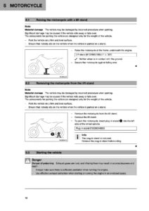
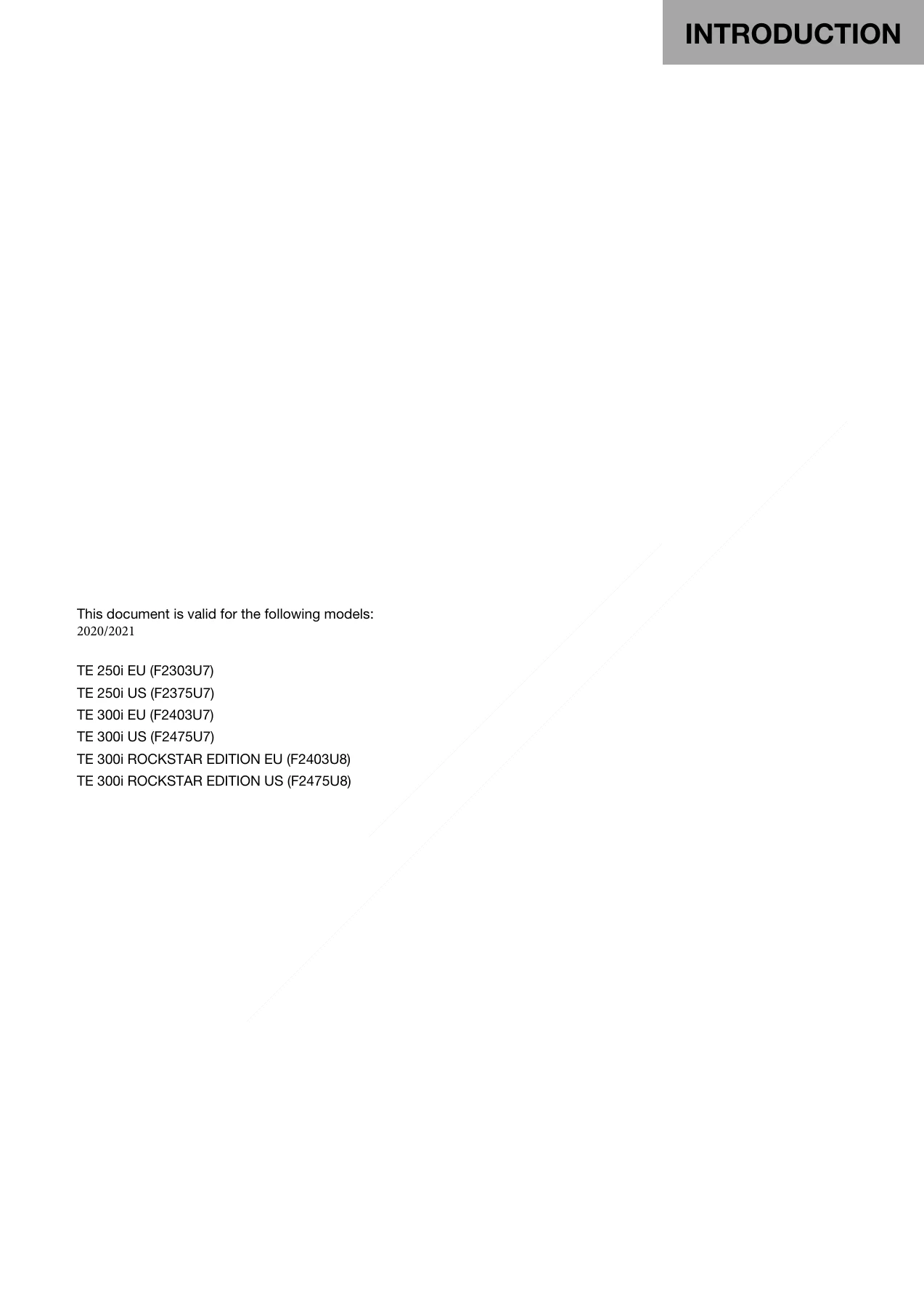
2020-2021 Husqvarna TE 250i TE 300i Repair Manual - Complete Workshop PDF — PDF page 3 preview
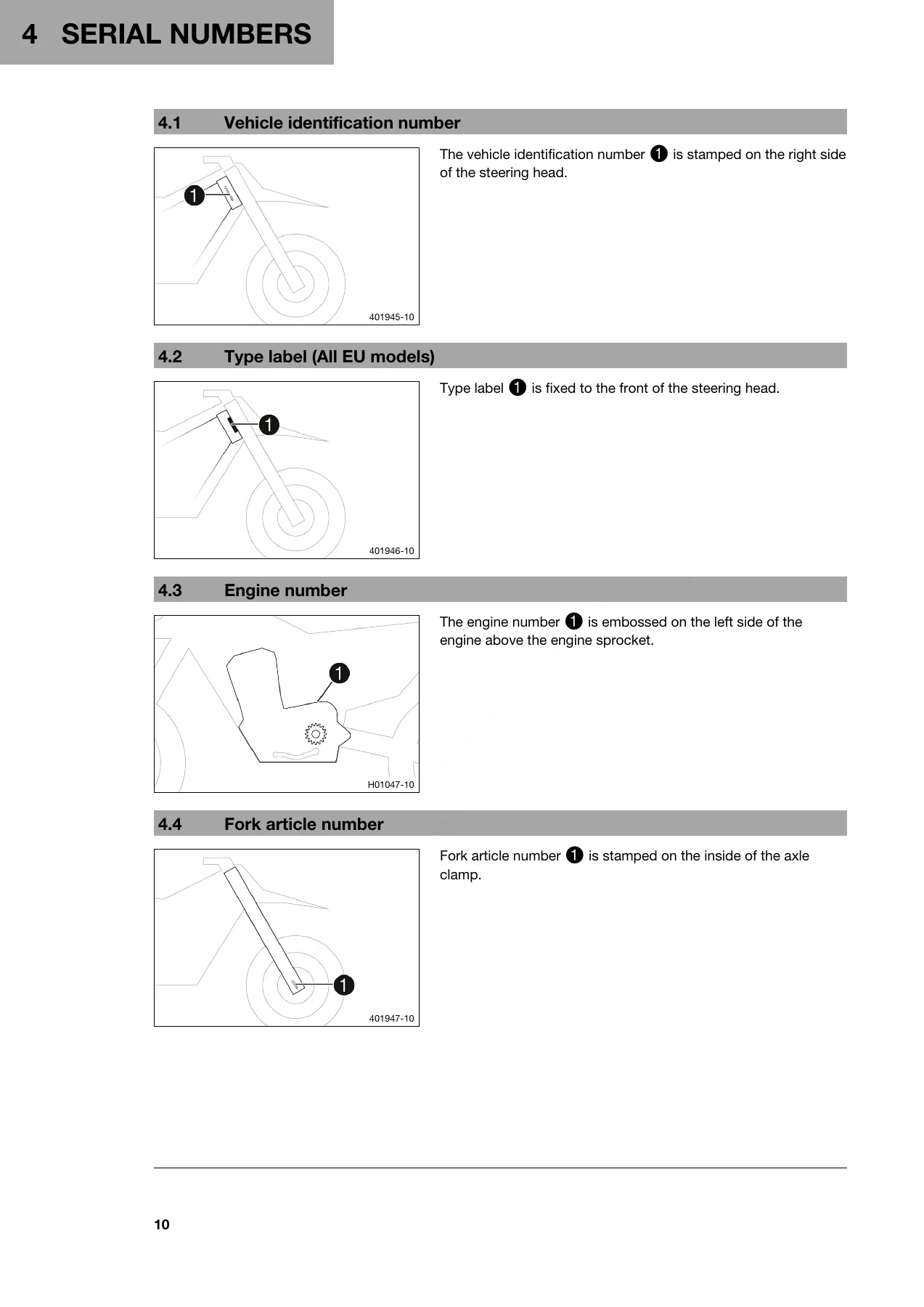
2020-2021 Husqvarna TE 250i TE 300i Repair Manual - Complete Workshop PDF — PDF page 12 preview
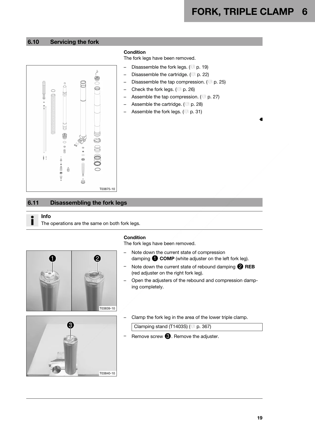
2020-2021 Husqvarna TE 250i TE 300i Repair Manual - Complete Workshop PDF — PDF page 21 preview

Instant PDF Delivery – No Shipping, Any Device

The 2020-2021 Husqvarna TE 250i TE 300i Repair Manual is delivered as an instant PDF download after purchase. There is no physical book to wait for and no shipping cost. The file can be opened on a laptop, tablet or smartphone in the workshop, printed page by page for the job at hand, or kept on a USB drive for quick reference. Because it is a PDF, sections can be printed and taken to the bench without risking the whole manual, and multiple copies can be kept in different locations. If you maintain, repair or rebuild a 2020 or 2021 Husqvarna TE 250i or TE 300i, this is the reference document that makes the job measurable.

Reviews

There are no reviews yet.

Be the first to review “2020-2021 Husqvarna TE 250i TE 300i Repair Manual – Complete Workshop PDF”

What Our Customers Say

★★★★★ Live reviews from customers
Loading customer reviews...
0
    0
    Your Cart
    Your cart is emptyReturn to Shop
    🛒
    Recently Purchased
    🕒 verified order