Description
2022 Bobcat S76 Skid-Steer Loader Service Manual 7399012enUS – S/N B4ZY11001 & Above
This 2022 Bobcat S76 Skid-Steer Loader Service Manual 7399012enUS – S/N B4ZY11001 & Above is a detailed mechanical service reference for the Bobcat S76. The manual states that it is intended for the Bobcat loader mechanic and provides servicing and adjustment procedures for the loader, its component parts and its systems. Across 917 PDF pages it follows repairs from routine service access and inspections through system testing, troubleshooting, component removal, installation, disassembly, assembly and specification checks.
The coverage applies to S76 S/N B4ZY11001 & Above. Its technical material spans the hydraulic and hydrostatic circuits, four-wheel drive system, loader structure, controls, electrical equipment, engine, emissions equipment and HVAC. The specification section identifies the engine as the 2,4L Bobcat Engine V2 Stage V and supplies performance, engine, drive, hydraulic, electrical, fluid and tyre data relevant to this loader configuration.
File Details
- Manual type: Service Manual
- Brand / model: Bobcat S76 Skid-Steer Loader
- Serial coverage: S/N B4ZY11001 & Above
- Document number: 7399012enUS
- Document marking: 02-22 (B)
- Language: English
- Pages: 917
- File format: PDF
- Publication: 2022
Mechanical Service and Repair Coverage
The Bobcat S76 service information is built around practical workshop procedures. Hydraulic components such as lift, tilt and Bob-Tach cylinders are not limited to identification: the manual includes testing, removal and installation, parts identification, disassembly and assembly procedures. Individual steps are illustrated with photographs and component drawings, while tightening values and service precautions are placed alongside the work where applicable.
Hydraulic diagnosis receives substantial attention. The manual includes a glossary of hydraulic symbols, troubleshooting information, system schematics and service procedures for the control valve, relief valves, hydraulic pumps, filters, reservoir, oil cooler, auxiliary hydraulic components and ride control equipment. Both standard-flow and high-flow hydraulic pump material appears in the hydraulic section, including pump testing, removal, installation, startup and internal service procedures where covered.
The hydrostatic and drive sections extend the repair scope into the propulsion system. One-speed and two-speed hydrostatic drive motors, motor carriers, charge-pressure checks, drive components, brake components and chaincase service are addressed. Troubleshooting information connects symptoms such as loss of drive, steering drift and hydrostatic overheating with possible system causes and the appropriate areas to inspect.
Engine, Maintenance and Diagnostic Information
The Bobcat S76 engine service section includes engine information, specifications, sensor locations, torque values, troubleshooting and engine removal and installation. It also contains compression testing, injector signal testing and oil-pressure testing procedures. The specification section identifies a four-cylinder 2400 cm3 (146.5 in3) 2,4L Bobcat Engine V2 Stage V, with diesel fuel, liquid cooling, turbo-charged and charged-air-cooled induction.
Emissions-system work includes diesel particulate filter information and regeneration procedures. Elsewhere in the manual, the maintenance chapters address fuel specifications and filters, engine oil and filter replacement, coolant service, hydraulic fluid and filters, final-drive chaincase fluid, lubrication points, tyre maintenance, Bob-Tach inspection and scheduled service intervals. The service schedule separates daily and operating-hour tasks from longer interval work, including engine oil, hydraulic filters, hydraulic reservoir service, fuel-system service and coolant replacement.
Electrical coverage includes connector information, electrical symbols, fuse and relay identification, solenoid testing, battery procedures and alternator service. Wiring schematic material for the S76 is also included. The manual additionally explains use of the Remote Start Tool for operations such as hydraulic testing, steering-linkage adjustment and electrical diagnostics, including the loader and computer service-tool harness arrangements.
Chapters Covered
- Safety & Maintenance
- Lifting and blocking the loader; lift arm support; operator cab service
- Transporting and towing procedures; Remote Start Tool service kit
- Service schedule and maintenance intervals
- Engine air cleaner, cooling, fuel and lubrication systems
- Diesel Particulate Filter (DPF) system
- Hydraulic fluid and filter maintenance; final drive transmission chaincases
- Hand lever and Power Bob-Tach inspection; machine lubrication and tyre maintenance
- Machine storage and return to service; emergency exits and seat belt inspection
- Hydraulic System
- Hydraulic system information, symbols and troubleshooting
- Lift, tilt and Bob-Tach cylinder testing and repair
- Main relief valve and hydraulic control valve
- Lift arm bypass control valve
- Standard-flow and high-flow hydraulic pumps
- Hydraulic filters, reservoir and oil cooler
- Bucket position sensors, auxiliary hydraulic components and automatic ride control
- Hydrostatic System
- Hydrostatic system troubleshooting
- One-speed and two-speed hydrostatic drive motors
- Hydrostatic motor carrier
- Charge pressure testing and service
- Drain manifold service
- Drive System
- Brake components
- Drive components, axle seals, axles, sprockets and bearings
- Drive-chain removal and installation
- Chaincase service
- Mainframe
- Seat bar service
- Operator cab removal, installation and related hardware
- Operator seat and seat belt service
- Suspension seat components
- Electrical System
- Electrical symbols, harness connectors and system description
- Fuse and relay identification and solenoid testing
- Battery removal, maintenance, testing, charging and jump starting
- Alternator and drive-belt service
- S76 wiring schematic information
- Engine Service
- Engine information, specifications, sensor locations and torque values
- Engine troubleshooting, removal and installation
- Compression, injector-signal and oil-pressure testing
- Diesel Particulate Filter system and regeneration procedures
- Heating, Ventilation and Air Conditioning (HVAC)
- Air-conditioning system flow, components and safety equipment
- HVAC filter, evaporator, heater-coil and condenser maintenance
- Air-conditioning system lubrication and belt service
- HVAC troubleshooting and service chart
- Specifications
- Machine dimensions and performance specifications
- Engine, drive-system and control specifications
- Hydraulic system and hydraulic cylinder specifications
- Electrical specifications, fluid capacities and tyre specifications
- Technical service guide data, engine torques, loader torques and hydraulic / hydrostatic service data
- Alphabetical Index
Taken as a whole, the 2022 Bobcat S76 Skid-Steer Loader Service Manual 7399012enUS – S/N B4ZY11001 & Above combines maintenance information with the deeper mechanical procedures required when a system has to be tested or a component must be removed and repaired. Photographic sequences identify access points and fasteners, exploded illustrations show internal component relationships, and hydraulic and wiring schematics help trace system operation. Specification and torque information is integrated with the repair material so that components can be checked and reassembled to the values stated for the machine.
Complete PDF Bookmark Tree
Complete Bookmarks
The complete bookmarks in the “2022 Bobcat S76 Skid-Steer Loader Service Manual 7399012enUS – S/N B4ZY11001 & Above” are as follows:
MAINTENANCE SAFETYp. 3
CONTENTSp. 5
+FOREWORDp. 7
FOREWORDp. 9
SAFETY INSTRUCTIONSp. 11
+FIRE PREVENTIONp. 13
Maintenancep. 13
Operationp. 13
Electricalp. 13
Hydraulic Systemp. 13
Fuelingp. 13
Startingp. 13
Spark Arrester Exhaust Systemp. 13
Welding And Grindingp. 14
Fire Extinguishersp. 14
+MACHINE SERIAL NUMBER LOCATIONSp. 15
Machine Serial Number Locationp. 15
Engine Serial Number Locationp. 15
DELIVERY REPORTp. 16
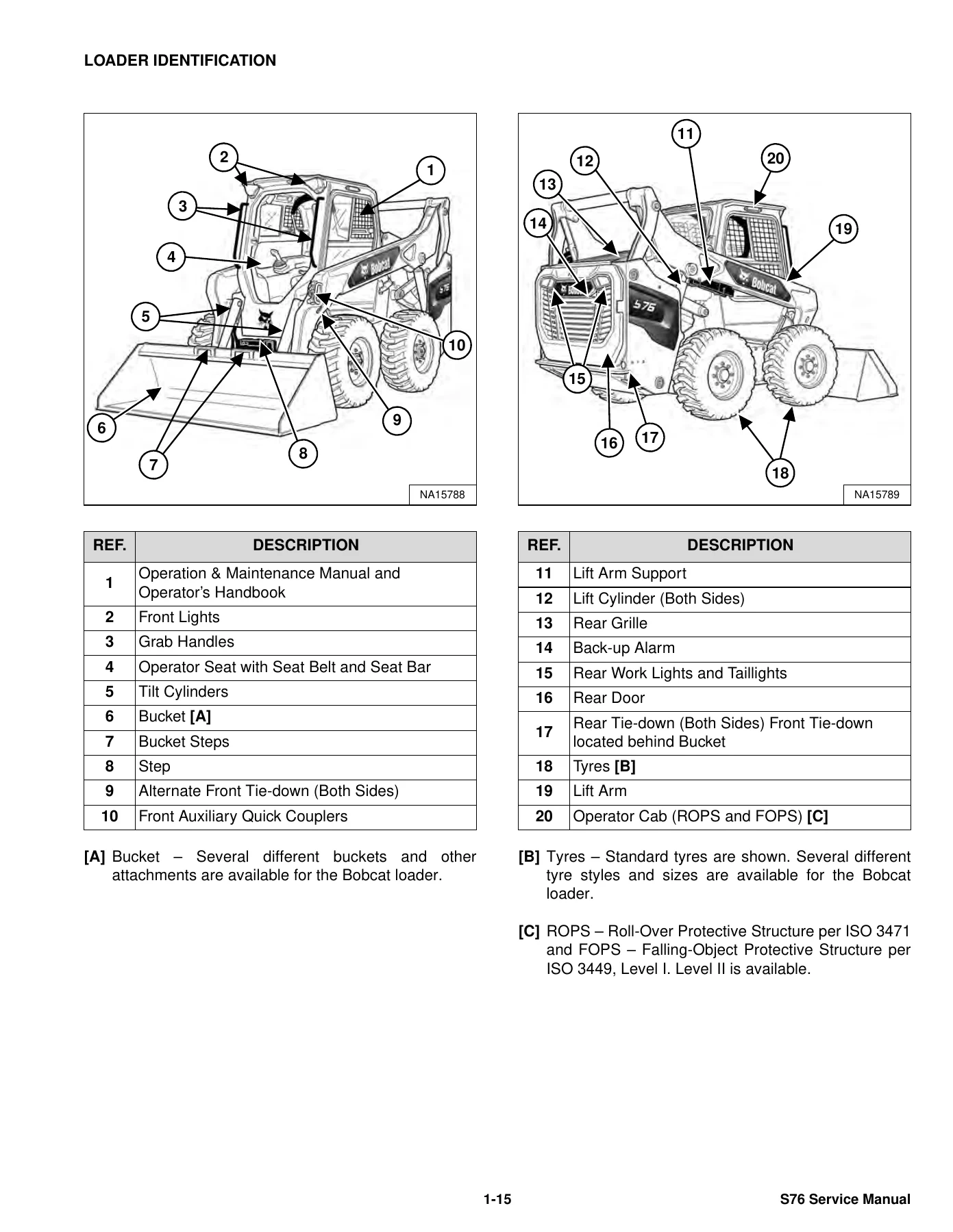
LOADER IDENTIFICATIONp. 17
+SAFETY & MAINTENANCEp. 19
+LIFTING AND BLOCKING THE LOADERp. 23
+LIFT ARM SUPPORTp. 25
Lift Arm Support Descriptionp. 25
Installing Lift Arm Supportp. 25
Removing Lift Arm Supportp. 27
+OPERATOR CABp. 29
Inspecting Operator Cabp. 29
Cab Door Sensor Descriptionp. 29
Raising Operator Cabp. 30
Lowering Operator Cabp. 32
Clear Side Enclosed Cab Optionp. 34
Inspecting And Maintaining Clear Side Enclosed Cab Optionp. 34
Special Applications Kitp. 34
Inspecting And Maintaining Special Applications Kitp. 34
Forestry Door And Window Kitp. 35
Inspecting And Maintaining Forestry Door And Window Kitp. 35
+TRANSPORTING THE MACHINE ON A TRAILERp. 37
Loading And Unloading Machinep. 37
Fastening Machine To Transport Vehiclep. 38
+TOWING THE MACHINEp. 39
+REMOTE START TOOL (SERVICE TOOL) KIT – 7217666p. 41
Descriptionp. 41
Remote Start Tool (Service Tool) – 7022042p. 42
Loader Service Tool Harness – 6689747p. 43
Computer Service Tool Harness – 6689746p. 44
Remote Start Procedurep. 45
+SERVICE SCHEDULEp. 49
Maintenance Intervalsp. 49
Service Schedule Symbolsp. 52
+ENGINE AIR CLEANERp. 53
Replacing Engine Air Filter Element (Outer)p. 53
Replacing Engine Air Filter Element (Inner)p. 54
+ENGINE COOLING SYSTEMp. 55
Cleaning Engine Cooling Systemp. 55
Checking And Adding Coolantp. 57
Replacing Coolantp. 58
+FUEL SYSTEMp. 61
Fuel Specificationsp. 61
Biodiesel Blend Fuelp. 61
Filling The Fuel Tankp. 62
Removing Water From Main Fuel Filterp. 63
Replacing Fuel Pre-Filterp. 64
Replacing Main Fuel Filterp. 65
Replacing Fuel Tank Vent Filterp. 67
+DIESEL PARTICULATE FILTER (DPF) SYSTEMp. 69
Descriptionp. 69
DPF Service Regenerationp. 69
DPF Cleaningp. 70
+ENGINE LUBRICATION SYSTEMp. 71
Checking And Adding Engine Oilp. 71
Engine Oil Chartp. 71
Replacing Engine Oil And Filterp. 72
+HYDRAULIC SYSTEMp. 75
Checking And Adding Hydraulic Fluidp. 75
Hydraulic Fluid Chartp. 76
Replacing Hydraulic Fluidp. 77
Replacing Main Hydraulic Filterp. 81
Replacing Hydraulic Case Drain Filterp. 83
Replacing Hydraulic Charge Filterp. 84
Replacing Hydraulic Reservoir Vent Filterp. 86
+FINAL DRIVE TRANSMISSION (CHAINCASES)p. 87
Checking And Adding Chaincase Fluidp. 87
Replacing Chaincase Fluidp. 88
+BOB-TACH (HAND LEVER)p. 89
Inspecting And Maintaining Hand Lever Bob-Tachp. 89
+BOB-TACH (POWER)p. 91
Inspecting And Maintaining Power Bob-Tachp. 91
+MACHINE LUBRICATIONp. 93
Lubricating Grease Fittingsp. 93
+TYRE MAINTENANCEp. 95
Checking Wheel Nut Torquep. 95
Rotating Tyrep. 95
Mounting Tyresp. 96
+PIVOT PINSp. 97
Checking Pivot Pin Torquep. 97
+MACHINE STORAGE AND RETURN TO SERVICEp. 99
Machine Extended Storage Procedurep. 99
Machine Return To Service Procedurep. 99
STOPPING THE ENGINE AND LEAVING THE MACHINEp. 101
+EMERGENCY EXITSp. 103
Removing Rear Window With Latchesp. 103
Removing Rear Window With Rubber Cordp. 103
Removing Rear Window With Latches From Outside Loaderp. 104
Removing Rear Window With Rubber Cord From Outside Loaderp. 105
Removing Front Doorp. 105
Front Door Reassemblyp. 106
+SEAT BELTp. 107
Inspection And Maintenancep. 107
+HYDRAULIC SYSTEMp. 109
+HYDRAULIC / HYDROSTATIC SCHEMATICSp. 113
+MANUAL WITH NO OPTIONSp. 113
S/N B4ZY110011 & Abovep. 113
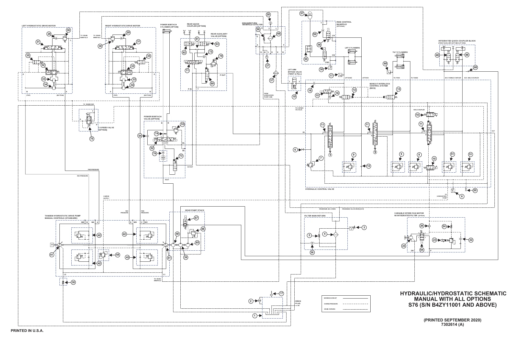
+MANUAL WITH ALL OPTIONSp. 115
S/N B4ZY110011 & Abovep. 115
+SJC WITH NO OPTIONSp. 117
S/N B4ZY110011 & Abovep. 117
+SJC WITH ALL OPTIONSp. 119
S/N B4ZY110011 & Abovep. 119
+HYDRAULIC SYSTEM INFORMATIONp. 121
Glossary Of Hydraulic Symbolsp. 121
Troubleshootingp. 125
+CYLINDER (LIFT)p. 127
Testingp. 127
Removal And Installationp. 128
Parts Identificationp. 132
Disassemblyp. 133
Assemblyp. 136
+CYLINDER (TILT)p. 141
Testingp. 141
Removal And Installationp. 142
Base End Pivot Pin Removal And Installationp. 144
Parts Identificationp. 145
Disassemblyp. 146
Assemblyp. 149
+CYLINDER (BOB-TACH)p. 153
Testingp. 153
Removal And Installationp. 154
Parts Identificationp. 155
Disassemblyp. 156
Assemblyp. 157
+MAIN RELIEF VALVEp. 161
Descriptionp. 161
Testingp. 162
Main Relief Valve Removal And Installationp. 164
+HYDRAULIC CONTROL VALVEp. 165
Descriptionp. 165
Removal And Installationp. 165
Actuator Removal And Installationp. 170
Identification Chartp. 173
Lift Load Check Valve Removal And Installationp. 174
Anti-Cavitation Valve Removal And Installation (Lift, Rod End)p. 176
Port Relief / Anti-Cavitation Valve Removal And Installation (Lift, Base End)p. 176
Port Relief / Anti-Cavitation Valve Removal And Installation (Tilt, Base End)p. 177
Port Relief / Anti-Cavitation Valve Removal And Installation (Tilt, Rod End)p. 177
Port Relief Valve Removal And Installationp. 178
Plug Removal And Installationp. 179
End Cap Block Removal And Installationp. 180
Lift Spool Removal And Installationp. 180
Lift Spool Disassembly And Assemblyp. 182
Tilt Spool Removal And Installationp. 183
Tilt Spool Disassembly And Assemblyp. 184
Auxiliary Spool Removal And Installationp. 185
Solenoid Removal And Installationp. 186
BICS™ Lock Valve Removal And Installationp. 187
Lift Arm Bypass Orifice Removal And Installationp. 189
Main Relief Valve Removal And Installationp. 189
Screen Fitting Removal And Installationp. 190
+LIFT ARM BYPASS CONTROL VALVEp. 191
Descriptionp. 191
Testingp. 191
Removal And Installationp. 192
Bracket Removal And Installationp. 193
Disassembly And Assemblyp. 193
+HYDRAULIC PUMP (STANDARD FLOW)p. 195
Descriptionp. 195
Pump Test At Quick Couplersp. 195
Direct Pump Test (Standard Section)p. 196
Direct Pump Test (Charge Section)p. 198
Removal And Installationp. 200
Hydraulic Pump Startupp. 202
Parts Identificationp. 203
Disassembly And Assemblyp. 204
+HYDRAULIC PUMP (HIGH FLOW)p. 205
Descriptionp. 205
Direct Pump Test (Standard Section)p. 207
Direct Pump Test (Charge Section)p. 208
Direct Pump Test (High Flow Section)p. 210
High Flow Relief Valve Adjustmentp. 212
High Flow Relief Valve Removal And Installationp. 213
Solenoid Removal And Installationp. 214
Removal And Installationp. 215
Hydraulic Pump Startupp. 217
Parts Identificationp. 218
Disassembly And Assemblyp. 219
+HYDRAULIC PUMP (STANDARD FLOW) (S/N B4ZY11503 AND ABOVE)p. 221
Descriptionp. 221
Pump Test At Quick Couplersp. 221
Direct Pump Test (Standard Section)p. 222
Direct Pump Test (Charge Section)p. 224
Removal And Installationp. 226
Hydraulic Pump Startupp. 228
Parts Identificationp. 229
Disassembly And Assemblyp. 230
+HYDRAULIC FILTERSp. 231
Descriptionp. 231
Main Filter Housing Removal And Installationp. 231
+HYDRAULIC FLUID RESERVOIRp. 233
Descriptionp. 233
Removal And Installationp. 234
+OIL COOLERp. 237
Descriptionp. 237
Removal And Installationp. 237
+BUCKET POSITION SENSORSp. 239
Descriptionp. 239
Removal And Installationp. 239
+REAR AUXILIARY DIVERTER VALVEp. 241
Descriptionp. 241
Removal And Installationp. 241
Disassembly And Assemblyp. 243
+BOB-TACH (POWER) BLOCKp. 249
Descriptionp. 249
Testing Relief Valvep. 250
Removal And Installationp. 252
Disassembly And Assemblyp. 254
+FRONT AUXILIARY HYDRAULIC COUPLER BLOCKp. 259
Descriptionp. 259
Removal And Installationp. 260
Disassembly And Assemblyp. 260
+AUTOMATIC RIDE CONTROLp. 263
Descriptionp. 263
Removal and Installationp. 264
Checking The Pressure In The Accumulatorp. 266
Adding Nitrogen To The Accumulatorp. 268
+HYDROSTATIC SYSTEMp. 271
+HYDROSTATIC SYSTEM INFORMATIONp. 273
+HYDROSTATIC DRIVE MOTOR (ONE-SPEED)p. 275
Descriptionp. 275
Removal And Installationp. 276
Disassembly And Assemblyp. 278
+HYDROSTATIC DRIVE MOTOR (TWO-SPEED)p. 283
Descriptionp. 283
Removal And Installationp. 284
Disassembly And Assemblyp. 286
+HYDROSTATIC MOTOR CARRIERp. 291
Descriptionp. 291
Removal And Installationp. 292
Disassemblyp. 295
Assemblyp. 297
+CHARGE PRESSUREp. 299
Descriptionp. 299
Testingp. 299
Sender Removal And Installationp. 300
Adjusting And Inspecting (SJC)p. 301
+HYDROSTATIC PUMP (MANUAL)p. 303
Descriptionp. 303
Port Locations And Gauge Installationp. 304
Removal And Installationp. 305
Hydrostatic Pump Startupp. 307
Disassembly And Assemblyp. 308
+HYDROSTATIC PUMP (SJC)p. 319
Descriptionp. 319
Port Locations And Gauge Installationp. 320
Removal And Installationp. 321
Hydrostatic Pump Startupp. 324
Parts Identificationp. 325
Parts Identificationp. 327
High Pressure Relief And Bypass Valvep. 328
Charge Pressure Relief Valvep. 329
Disassembly And Assemblyp. 330
Mechanical Neutral Adjustmentp. 342
Hydraulic Controller Neutral Adjustmentp. 344
+TWO-SPEED VALVEp. 347
Descriptionp. 347
Valve Block Removal And Installationp. 348
Valve Block Disassembly And Assemblyp. 349
+DRAIN MANIFOLDp. 351
Descriptionp. 351
Drain Manifold Housing Removal And Installationp. 351
+DRIVE SYSTEMp. 353
+BRAKEp. 355
Descriptionp. 355
Block Removal And Installationp. 355
Block Disassembly And Assemblyp. 356
+DRIVE COMPONENTSp. 357
Descriptionp. 357
Axle Seal Removal And Installationp. 358
Axle, Sprocket And Bearings Removal And Installationp. 360
Chain Removal And Installationp. 365
+CHAINCASEp. 367
Descriptionp. 367
Chaincase Cover Removal And Installationp. 367
+MAINFRAMEp. 369
+SEAT BARp. 373
Descriptionp. 373
Removal And Installationp. 373
Disassembly And Assemblyp. 374
Compression Spring Disassembly And Assemblyp. 375
+OPERATOR CABp. 377
Gas Spring Removal And Installationp. 377
Gas Spring Bracket Disassembly And Assemblyp. 378
Removal And Installationp. 379
+OPERATOR SEATp. 381
Removal And Installationp. 381
Seat Belt Removal And Installation (Two Point)p. 381
Seat Belt Removal And Installation (Three Point)p. 382
+OPERATOR SEAT (SUSPENSION)p. 385
Removal And Installationp. 385
Slide Rail Removal And Installationp. 385
Seat Belt Removal And Installationp. 386
Lower Cushion Removalp. 386
Lower Cushion Installationp. 387
Back Cushion Removal And Installationp. 387
Shock Removal And Installationp. 388
3-Point Seat Belt Removal And Installationp. 388
+BOB-TACH (HAND LEVER)p. 391
Descriptionp. 391
Removal And Installationp. 391
Lever And Wedge Disassembly And Assemblyp. 394
Pivot Pin Bushing And Seal Removal And Installationp. 395
+BOB-TACH (POWER)p. 397
Descriptionp. 397
Removal And Installationp. 397
Lever And Wedge Disassembly And Assemblyp. 400
Pivot Pin Bushing And Seal Removal And Installationp. 401
+LIFT ARMSp. 403
Driver Link Removal And Installationp. 403
Follower Link Removal And Installationp. 406
Lift Arm Removal And Installationp. 407
+REAR GRILLEp. 411
Raising Rear Grillep. 411
Lowering Rear Grillep. 412
Shield Removal And Installationp. 412
+REAR DOOR (TAILGATE)p. 413
Removal And Installationp. 413
Striker Removal And Installationp. 414
Striker Disassembly And Assemblyp. 414
Striker (Adjusting)p. 415
Latch Removal And Installationp. 415
+FUEL TANKp. 417
Removal And Installationp. 417
Fuel Level Sender Removal And Installationp. 419
Fuel Tank Vent Removal And Installationp. 420
+CONTROL PEDALS (MANUAL)p. 421
Descriptionp. 421
Pedal Removal And Installation (Right Side)p. 421
Pedal Removal And Installation (Left Side)p. 421
Pedal (Adjusting)p. 422
+FOOTREST (SJC)p. 423
Footrest Removal And Installation (Right Side)p. 423
Footrest Removal And Installation (Left Side)p. 423
+CONTROL LEVER ASSEMBLYp. 425
Descriptionp. 425
Linkage Removal And Installationp. 426
Removal And Installationp. 427
Disassembly And Assemblyp. 428
+CONTROL LEVER CENTERING ASSEMBLYp. 431
Descriptionp. 431
Disassembly And Assemblyp. 432
Linkage Neutral (Adjusting)p. 436
Linkage Travel (Adjusting)p. 439
Shock Removal And Installationp. 443
+CONTROL HANDLE / LEVER (MANUAL)p. 445
Descriptionp. 445
Lever Removal And Installationp. 445
+CONTROL HANDLE / LEVER (SJC)p. 447
Descriptionp. 447
Joystick Testingp. 447
Joystick Removal And Installationp. 448
+ACCESS PANELS (LOWER)p. 451
Removal And Installation (Left Side)p. 451
Removal And Installation (Right Side)p. 453
+ACCESS PANELS (UPPER)p. 455
Removal And Installation (Center Panel)p. 455
Removal And Installation (Left Side)p. 455
Removal And Installation (Right Side)p. 456
+WINDOW (REAR)p. 457
Removing Rear Window With Latchesp. 457
Removing Rear Window With Rubber Cordp. 457
Removing Rear Window With Latches From Outside Loaderp. 458
Disassembly And Assembly (Latches)p. 459
Removal (Rubber Cord)p. 460
Installation (Rubber Cord)p. 461
+WINDOW (TOP)p. 463
Removal And Installationp. 463
+WINDOW (SIDE)p. 465
Removal And Installationp. 465
+CAB DOORp. 467
Descriptionp. 467
Removal And Installationp. 467
Disassembly And Assemblyp. 468
Aligningp. 470
Adjustingp. 470
Checking Operationp. 471
+ARMRESTp. 473
Descriptionp. 473
Removal And Installationp. 473
Disassembly And Assemblyp. 475
+HEADLINERp. 477
Removal And Installationp. 477
+ELECTRICAL SYSTEMp. 481
+ELECTRICAL SCHEMATICSp. 487
+STANDARD MACHINEp. 487
S/N B4ZY11001 & Abovep. 487
+ELECTRICAL SYSTEMp. 510
Glossary Of Electrical Symbolsp. 510
Standard Cab Harness Connectorsp. 513
Deluxe Cab Harness Connectorsp. 514
Mainframe Harness Connectorsp. 515
Electrical System Descriptionp. 516
Fuse And Relay Identificationp. 517
Solenoid Testingp. 521
+BATTERYp. 522
Removing And Installing Batteryp. 522
Battery Maintenancep. 523
Maintaining Battery Charge Levelp. 523
Battery Service During Machine Storagep. 523
Testing Batteryp. 524
Charging Batteryp. 524
Using A Booster Battery (Jump Starting)p. 525
+ALTERNATORp. 526
Adjusting Belt (Machines Without Air Conditioning)p. 526
Replacing Belt (Machines Without Air Conditioning)p. 526
Adjusting Belt (Machines With Air Conditioning)p. 527
Replacing Belt (Machines With Air Conditioning)p. 527
Charging System Inspectionp. 528
Alternator Voltage Testingp. 529
Low Voltage Testingp. 530
High Voltage Testingp. 530
Removal And Installation (Machines Without Air Conditioning)p. 531
Removal And Installation (Machines With Air Conditioning)p. 532
Parts Identificationp. 533
+STARTERp. 534
Testingp. 534
Removal And Installationp. 534
Parts Identificationp. 535
+INSTRUMENT PANEL IDENTIFICATIONp. 536
Instrument Panel Overviewp. 536
Standard Displayp. 537
Touch Displayp. 539
Left Control Panelp. 541
Right Control Panelp. 541
Jog Shuttle (Standard Display)p. 542
Jog Shuttle (Touch Display)p. 542
Heating, Ventilation, And Air Conditioning (HVAC) Controlsp. 543
Touch Display Radio Input Portsp. 543
Keyed Ignitionp. 544
Radio Identificationp. 545
Left Switch Panel Removal And Installationp. 547
Right Switch Panel Removal And Installationp. 548
+LIGHTSp. 550
Front Removal And Installationp. 550
Rear Removal And Installationp. 550
Cab Light Removal And Installationp. 551
Side Light Removal And Installationp. 551
+BOBCAT HUB CONTROLLERp. 552
Descriptionp. 552
Connector Identificationp. 553
Removal And Installationp. 556
+BOBCAT MID CONTROLLERp. 560
Descriptionp. 560
Removal And Installationp. 561
+BOBCAT CONTROLLER (SJC) (DRIVE)p. 562
Descriptionp. 562
Removal And Installationp. 563
+ENGINE CONTROL UNIT (ECU)p. 564
Descriptionp. 564
Cleaningp. 565
Removal And Installationp. 566
+DIAGNOSTIC SERVICE CODESp. 568
+BOBCAT INTERLOCK CONTROL SYSTEM (BICS™)p. 574
Inspecting The Bobcat Interlock Control System (BICS™)p. 574
Inspecting The Lift Arm Bypass Controlp. 575
+SEAT BAR SENSORp. 576
Descriptionp. 576
Troubleshootingp. 576
Testingp. 577
Removal And Installationp. 578
Bobcat Interlock Control System (BICS™) Circuit Testp. 581
+TRACTION LOCKp. 584
Descriptionp. 584
Troubleshootingp. 585
Operating Parking Brakep. 586
Operating Hydraulic Controls With Parking Brake Engagedp. 586
+CONTROL IDENTIFICATIONp. 588
Identification Chart (Standard)p. 588
Identification Chart (SJC)p. 589
+SERVICE PC (LAPTOP COMPUTER)p. 590
Connecting Remote Start Tool (Service Tool)p. 590
+CALIBRATIONp. 592
Descriptionp. 592
Actuator Testingp. 592
Lift And Tilt Calibration (SJC)p. 595
Adjusting Lift And Tilt Compensationp. 595
Hydrostatic Pump Calibration (SJC)p. 598
+STEERING DRIFT COMPENSATIONp. 604
Steering Drift Compensation Descriptionp. 604
Adjusting Steering Drift Compensationp. 605
+NAVIGATION (STANDARD DISPLAY)p. 608
Navigation Barp. 608
Viewing Active Shortcutsp. 608
+VITALS (STANDARD DISPLAY)p. 610
Vital Detail And Machine Performancep. 610
+SERVICE (STANDARD DISPLAY)p. 612
+SETTINGS (STANDARD DISPLAY)p. 614
Display Settingsp. 614
Machine Settingsp. 615
Language Settingsp. 616
Unitsp. 617
Softwarep. 618
+PASSWORD SETUPp. 620
Security Settingsp. 620
Security Settings (Manage Operators)p. 621
+CAMERA (TOUCH DISPLAY)p. 622
PHONE (TOUCH DISPLAY)p. 624
AUDIO (TOUCH DISPLAY)p. 626
+SERVICE (TOUCH DISPLAY)p. 628
Record A Servicep. 628
View Service Schedulep. 629
View Service Recordp. 630
View Service Codesp. 631
+ATTACHMENTS (TOUCH DISPLAY)p. 632
Attachment Informationp. 632
+SETTINGS (TOUCH DISPLAY)p. 634
Favoritesp. 634
Display Settingsp. 636
Machine Settingsp. 637
Security Settingsp. 638
Security Settings (Manage Operators)p. 639
Operator Statisticsp. 643
Job Clocksp. 644
Language Settingsp. 646
Unitsp. 647
Camera Settingsp. 647
Bluetooth® Settingsp. 647
Audio Settingsp. 647
Dealerp. 648
Softwarep. 649
+DISPLAY PROGRAMMING AND USB PORT LOCATIONSp. 650
Overviewp. 650
Procedurep. 650
+PASSWORD SETUPp. 652
Security Settingsp. 652
Security Settings (Manage Operators)p. 653
+MAINTENANCE CLOCKp. 654
Record A Servicep. 654
View Service Codesp. 655
+BACK-UP ALARM SYSTEMp. 656
Inspecting Back-Up Alarm Systemp. 656
Adjusting Back-Up Alarm Switchesp. 657
Troubleshooting (Joystick)p. 658
Alarm Removal And Installationp. 659
+FRONT HORNp. 660
Removal And Installationp. 660
Troubleshootingp. 661
+ENGINE SPEED CONTROL (HAND)p. 662
Descriptionp. 662
Removal And Installationp. 663
+ENGINE SPEED CONTROL (FOOT)p. 664
Descriptionp. 664
Removal And Installationp. 664
Disassembly And Assemblyp. 665
+CAMSHAFT AND CRANKSHAFT POSITION SENSORp. 668
Removal And Installationp. 668
+MACHINE IQp. 670
Descriptionp. 670
Removal And Installationp. 670
Procedurep. 671
+ENGINE SERVICEp. 672
+ENGINE INFORMATIONp. 676
Descriptionp. 676
Specificationsp. 677
Sensor Locationp. 679
Torque Valuesp. 686
Troubleshootingp. 688
Engine Removal And Installationp. 690
Engine Mount Replacementp. 697
Compression – Testingp. 699
Injector Signal Testing (In-Line)p. 701
Oil Pressure Testing (At Turbocharger Oil Inlet)p. 703
+DIESEL PARTICULATE FILTER (DPF) SYSTEMp. 706
Descriptionp. 706
DPF Regeneration Status Iconsp. 706
DPF Regeneration Tablesp. 707
Removal And Installationp. 709
Automatic Regeneration Operationp. 711
Forced Regeneration Operationp. 712
Forced Parked Regeneration Operationp. 713
Inhibit Mode Operationp. 715
+AIR CLEANERp. 718
Housing Removal And Installationp. 718
+ENGINE COOLING SYSTEMp. 720
Radiator Cooling Package Removal And Installationp. 720
Hydraulic Fan Descriptionp. 723
Reversible Hydraulic Fan Descriptionp. 723
Hydraulic Fan Motor Assembly Removal And Installationp. 724
Hydraulic Fan Motor Removal And Installationp. 727
Hydraulic Fan Motor Disassembly And Assemblyp. 729
Water Pump Removal And Installationp. 737
Thermostat Housing Removal And Installationp. 738
Testing The Thermostatp. 739
+LUBRICATION SYSTEMp. 740
Descriptionp. 740
Oil Pan Removal And Installationp. 741
Oil Pump Removal And Installationp. 742
Oil Pump Relief Valve Descriptionp. 743
Oil Pump Relief Valve Removal And Installationp. 743
Oil Cooler Removal And Installationp. 743
Oil Filter Head Removal And Installationp. 744
Oil Cooler Bypass Descriptionp. 746
Oil Cooler Bypass Removal And Installationp. 746
+FUEL SYSTEMp. 748
Descriptionp. 748
Fuel Filter Housing Removal And Installationp. 749
Fuel Lift Pump Removal And Installationp. 750
Fuel Lift Pump Filter Removal And Installationp. 751
Transfer Pump / High Pressure Pump Removal And Installationp. 751
Fuel Temperature Sensor Removal And Installationp. 753
Fuel Recirculation Valve (FRV) Removal And Installationp. 754
Fuel Pressure Relief Valve Removal And Installationp. 754
Fuel Rail Assembly Removal And Installationp. 755
Fuel Injector Removal And Installationp. 756
Injector Codingp. 759
+CYLINDER HEADp. 762
Glow Plugs Testingp. 762
Glow Plug Removal And Installationp. 763
Cylinder Head Removal And Installationp. 764
Cylinder Head Disassembly And Assemblyp. 767
Cylinder Head Inspectionp. 768
Cylinder Head Top Clearancep. 769
Valve Step Heightp. 770
Valve Stem Heightp. 770
Valve Guidep. 771
Valvep. 771
Valve Springp. 772
Rocker Arm Shaft Disassembly And Assemblyp. 773
Rocker Arm Shaft Inspectionp. 774
Push Rod Inspectionp. 774
+CRANKSHAFT AND PISTONSp. 776
Piston And Connecting Rod Removal And Installationp. 776
Piston And Connecting Rod Inspectionp. 777
Crankshaft Removal And Installationp. 779
Cylinder Block Inspectionp. 782
Crankshaft Inspectionp. 784
Connecting Rod Inspectionp. 784
Engine Component Classp. 785
+CAMSHAFTp. 788
Removal And Installationp. 788
Inspectingp. 789
+GEARCASEp. 792
Gearcase Cover Removal And Installationp. 792
Gear Backlashp. 793
Gear Timingp. 794
Idle Gear Removal And Installationp. 795
Idle Gear Inspectionp. 795
+TURBOCHARGERp. 796
Descriptionp. 796
Removal And Installationp. 796
Inspectionp. 799
+FLYWHEEL AND HOUSINGp. 800
Flywheel Removal And Installationp. 800
Ring Gear Removal And Installationp. 801
Housing Removal And Installationp. 802
+EXHAUST GAS RECIRCULATION (EGR) SYSTEMp. 804
Descriptionp. 804
Removal And Installationp. 805
+EXHAUST MANIFOLDp. 808
Removal And Installationp. 808
+HEATING, VENTILATION AND AIR CONDITIONING (HVAC)p. 810
+AIR CONDITIONING SYSTEM FLOWp. 812
Descriptionp. 812
Chartp. 813
Componentsp. 814
Safety Equipmentp. 817
+REGULAR MAINTENANCEp. 818
Cleaning HVAC Filtersp. 818
Cleaning Air Conditioning Evaporator And Heater Coilp. 819
Cleaning Air Conditioning Condenserp. 820
Lubricating Air Conditioning Systemp. 820
Troubleshooting HVAC Systemp. 820
Adjusting Beltp. 821
Replacing Beltp. 821
Air Conditioning Service Chartp. 822
+TROUBLESHOOTINGp. 824
Blower Motor Does Not Operatep. 824
Blower Motor Operates Normally, But Air Flow Is Insufficientp. 824
Insufficient Cooling Although Air Flow And Compressor Operation Are Normalp. 824
The Compressor Does Not Operate At All, Or Operates Improperlyp. 824
Gauge Pressure Related Troubleshootingp. 825
Troubleshooting Treep. 827
Temperature / Pressure Chartp. 831
Poor A/C Performancep. 833
HVAC Repair And Leaksp. 834
Electrical Systemp. 835
Engine Coolant Bypassing The Heater Valvep. 841
Heater Valve Not Opening Or Closingp. 842
+SYSTEM CHARGING AND RECLAMATIONp. 844
Refrigerant Identificationp. 844
Reclamation And Charging With Recovery / Charging Unitp. 845
+COMPRESSORp. 848
Removal And Installationp. 848
Oilp. 849
Oil Checkp. 850
+CONDENSERp. 852
Removal And Installationp. 852
+RECEIVER / DRIER FILTER CARTRIDGEp. 854
Removal And Installationp. 854
+EVAPORATOR / HEATER UNITp. 856
Removal And Installationp. 856
+THERMOSTATp. 858
Descriptionp. 858
Removal And Installationp. 859
+EXPANSION VALVEp. 862
Removal And Installationp. 862
+EVAPORATOR COILp. 866
Removal And Installationp. 866
+HEATER COILp. 870
Removal And Installationp. 870
+BLOWER FANp. 872
Removal And Installationp. 872
Disassembly And Assemblyp. 873
+HEATER VALVEp. 876
Removal And Installationp. 876
+EVAPORATOR / HEATER COVERp. 878
Removingp. 878
Installingp. 879
+SPECIFICATIONSp. 880
+LOADER SPECIFICATIONSp. 882
Machine Dimensionsp. 882
Performance Specificationsp. 884
Engine Specificationsp. 884
Drive System Specificationsp. 885
Control Specificationsp. 885
Hydraulic System Specificationsp. 886
Hydraulic Cylinder Specificationsp. 886
Electrical System Specificationsp. 887
Fluid Capacitiesp. 887
Tyre Specificationsp. 887
Engine CO2 Emission Valuesp. 887
+TECHINCAL SERVICE GUIDE SPECIFICATIONSp. 888
Enginep. 888
Engine Torquesp. 888
Cooling Systemp. 888
Loader Torquesp. 889
Hydraulic / Hydrostatic Systemp. 889
Fuel Consumptionp. 889
+TORQUE SPECIFICATIONS FOR BOLTSp. 890
Torque For General SAE Boltsp. 890
Torque For General Metric Boltsp. 891
+HYDRAULIC CONNECTION SPECIFICATIONSp. 892
Straight Thread O-ring Fittingp. 892
Flare Fittingp. 893
Tubelines And Hosesp. 893
+HYDRAULIC FLUID SPECIFICATIONSp. 894
+CONVERSIONSp. 896
Decimal And Millimeter Equivalent Chartp. 896
U.S. To Metric Conversion Chartp. 896
+SERVICE TOOLS REQUIREDp. 898
Remote Start Toolsp. 898
Hydraulic Toolsp. 899
Mainframe And Drive Toolsp. 902
Electrical Toolsp. 905
Engine Toolsp. 906
HVAC Toolsp. 911
ALPHABETICAL INDEXp. 912
Specifications and Workshop Reference
The final specification material provides a concentrated reference for the Bobcat S76. It includes machine dimensions, rated operating and performance information, engine specifications, drive and control data, hydraulic system and cylinder information, electrical specifications, fluid capacities and tyre specifications. Technical service guide pages add engine and loader torque data along with hydraulic and hydrostatic service values.
Examples of the documented machine data include a rated operating capacity of 1361 kg (3000 lb), operating weight of 4038 kg (8903 lb), and an engine displacement of 2400 cm3 (146.5 in3). The drive system is described as fully hydrostatic four-wheel drive, using tandem hydrostatic piston pumps driving two fully reversing hydrostatic motors. Hydraulic schematic pages identify pressures, relief valves, filters, pumps, motors, control valves and circuit paths for configurations with and without options.
Repair Your Bobcat S76 With the Correct Service Information
The 2022 Bobcat S76 Skid-Steer Loader Service Manual 7399012enUS – S/N B4ZY11001 & Above supports jobs ranging from scheduled maintenance and fluid service to hydraulic cylinder overhaul, hydrostatic diagnosis, drive-system work, electrical troubleshooting, engine testing, component removal and reassembly, HVAC service and specification checks. Having the procedures, diagrams, torque values and service specifications for the correct serial-number range helps technicians follow the documented sequence instead of relying on general repair information.
Your manual is supplied as an instant PDF download after payment. There is no physical book and no shipping delay. The PDF can be opened on compatible computers, tablets and phones, kept available for workshop reference, and printed when a paper copy of selected service pages is useful.



Reviews
There are no reviews yet.