JCB Engines CHD Series Engine Workshop Manual – PDF DOWNLOAD
Original price was: $78.00.$28.95Current price is: $28.95.
JCB Engines CHD Series Engine Workshop Manual
Description
JCB Engines CHD Series Engine Workshop Manual
FILE DETAILS:
JCB Engines CHD Series Engine Workshop Manual
Size: 15.2 MB
Fomat: PDF
Language: English
Brand: JCB
Type of machine: Engines CHD Series Engine
Type of document: Workshop Manual
Model: 9806-4060
Page of number: 90
JCB ENGINES CHD SERIES ENGINE WORKSHOP MANUAL – PDF DOWNLOAD:
TABLE OF CONTENTS:
JCB Engines CHD Series Engine Workshop Manual
1 GENERAL REMARKS AND SAFETY INFORMATION 9 – 11
General safety during operating phases 11
General Service manual notes 9
Glossary and terminology 9
Safety and environmental impact 11
Safety and warning decals 10
Safety regulations 10
2 TECHNICAL INFORMATION 12 – 20
Approval data 14
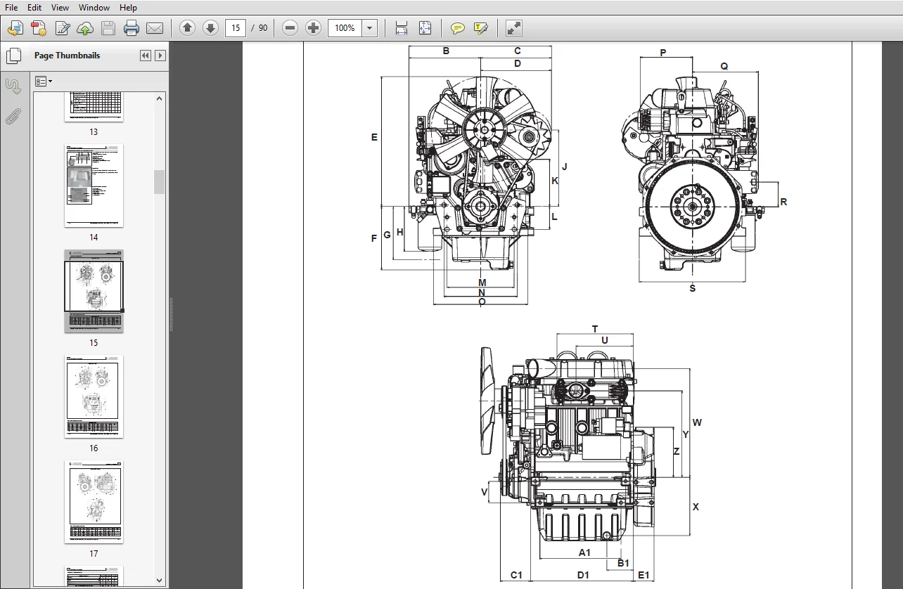
Overall dimensions 15
Performance diagrams 20
Possible causes and trouble shooting 12
Table of likely anomalies and their symptoms 12
18
3 MAINTENANCE – PRESCRIBED LUBRICANT – REFILLING 22 – 25
ACEA Regualtions – ACEA Sequences 23
API / MIL Sequences 23
Aviation fuel 25
Biodiesel fuel 25
Coolant 25
Extraordinary maintenance 22
Fuel recommendations 25
Fuel type 25
Fuels for low temperatures 25
Lubricant 23
Ordinary maintenance 22
Prescribed lubricant 24
Routine engine maintenance 22
4 DISASSEMBLY/REASSEMBLY 26 – 56
Assembling and tightening the cylinder head on engines with hydraulic tappets 39
Camshaft 51
Camshaft bushing replacement 52
Camshaft end play 56
Camshaft gear – Speed governor counter weights 50
Camshaft journals and bushings in model LDW 1503 52
Camshaft journals and bushings in models LDW 2004-2004/T 52
Camshaft removal 51
Camshaft timing 54
Center main bearings 42
Check clearance between main bearings and journals 43
Checking camshaft bushing internal diameter 52
Checking main journals and crank pins 46
Connecting rod 40
Connecting rod alignment 41
Connecting rod and piston pin 40
Connecting rod weights 40
Connecting rod/piston assemblies 41
CHAPTER INDEX
– 6 – Workshop Manual LDW CHD _ cod 15302345 – 6° ed_rev 05
– Chapter index
Cooling fan 29
Crankshaft end play 44
Crankshaft for engines with dynamic equalizer (only four-cylinder engines) 47
Crankshaft front and rear oil seal 45
Crankshaft lubrication ducts 45
Crankshaft timing gear 45
Cylinder head 31
Cylinder head gasket 38
Cylinder head tightening for engines without hydraulic tappets 39
Cylinder head tightening steps 39
Cylinder roughness 36
Cylinders 36
Dimensions for injection pump delivery control yoke adjustement 49
Driving pulley (2a PTO) 29
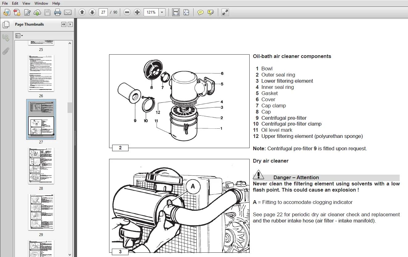
Dry air cleaner 27
Dry air components 28
Dynamic balancer (on request) – Adjustment of clearance between teeth D and ring gear A 47
Engines with hydraulic tappets 55
Engines with mechanical tappets 55
Exhaust manifold 28
Flywheel 30
Frame with idling speed governor spring 50
Front cover 48
GR 1 and GR 2 hydraulic pump 3rd pto 56
Hydraulic diagram for feeding the tappets 34
Hydraulic pump pto 56
Hydraulic tappet components: 34
Hydraulic tappet operation 35
Hydraulic tappet valve control 34
Idler gear and hub 48
Injection pump follower 35
Intake manifold 28
Intake, exhaust and injection cam height for models LDW 2004- 2004/T 53
Intake, exhaust and injecton cam height for model LDW 1503 53
Main bearing and connecting rod big bearing inside diameter (mm) 46
Main journal and connecting rod big end journal diameter 46
Oil seal in the valves guides, (intake and exhaust) 33
Oil-bath air cleaner 27
Oil-bath air cleaner components 27
Piston 36
Piston availability 36
Piston cooling sprayer 41
Piston position and clearance 38
Piston rings – Clearance between grooves 37
Piston rings – End gaps 37
Piston rings – Fitting sequence 37
Piston weight 37
Precombustion chamber 34
Recommendations for disassembling and assembling 26
Recommendations for overhauls and tuning 26
Rocker arm assemly 31
Rocker arm cover for engines with recirculating vent 30
Rocker arm cover with vent into the air 30
Speed governor 49
Speed governor counter springs 50
Spring for extra fuel supply at starting 51
Summary tables of the governor equipment according to the speed variation 51
Table of pin-rocker arm dimensions 31
Tank 29
Thrust bearing, oversizes 44
Thrust bearings 43
Timing angles for checking puposes 55
Timing angles for checking purposes LDW 2004/T 55
Timing angles for operating purposes 55
Timing angles for operating purposes LDW 2004/T 55
Workshop Manual LDW CHD _ cod 15302345 – 6° ed_rev 05 – 7 –
Chapter index –
Timing belt operating angles (with valve clearance set to zero) 55
V belt 29
Valve guide insertion, after driving 33
Valve guides and cylinder head 32
Valve material 32
Valve recess and sealing surfaces 33
Valve removal 31
Valve seats and bore 33
Valve spring – Check 32
Valve spring – check under load 32
Valve timing check 54
Valve timing without considering timing marks 54
5 TURBOCHARGER 58 – 59
Checking actuator setting – “Waste gate” valve control rod stroke adjustment 59
Turbocharger 58
Turbocharger components 58
Turbocharger Testing 58
6 LUBRICATION SYSTEM 60 – 62
Lubrication system layout 60
Oil pressure adjusting valve 61
Oil pressure check 62
Oil pressure curve for LDW 1503 – 1603 62
Oil pressure curve for LDW 2004 – 2204 62
Oil pressure curve for LDW 2004/T – 2204/T 62
Oil pump 61
Oil pump rotor clearance 61
7 COOLING SYSTEM 64 – 65
Cooling system layout 64
Expansion tank and cap 65
Checking for cooling system leaks 65
Coolant circulating pump 65
Thermostat 65
8 FUEL SYSTEM 66 – 72
Checking injection pump delivery 70
Checking low pressure injection timing for engines with hydraulic tappets 71
Checking low pressure injection timing for engines with mechanical tappets 71
Electric fuel pump (24V) 67
Fuel feeding pump 66
Fuel feeding pump drive rod protrusion 66
Fuel feeding/injection circuit 66
How to reassemble injection pump components 68
How to reassemble injection pump feeding tubes 69
How to remove injection pump feeding tubes 68
Injection pump 67
Injection pump control rod 68
Injection pump delivery equalization 69
Injection pump disassembly 67
Injection pump non-return valve 68
Injection pump P No 6590-249 – Plunger and barrel assembly 70
Injection timing correction by changing the pad thickness 72
Injector (pin type) 72
Injector setting 72
Instrument for equalizing injection pump delivery 69
Test data of injection pump 70
– 8 – Workshop Manual LDW CHD _ cod 15302345 – 6° ed_rev 05
– Chapter index
9 ELECTRIC SYSTEM73 – 82
Alternator type Iskra, AAK3139 14V 80A 75
Alternator type Marelli AA 125 R 14V 45A 73
Alternator type Marelli AA 125 R 14V 65A 74
Characteristic curves for alternator type Iskra, AAK3139 14V 80A 75
Characteristic curves for alternator type Marelli AA 125 R 14V 45A 73
Characteristic curves for alternator type Marelli AA 125 R 14V 65A 74
Characteristic curves for starting motor Iskra type AZE 4598 24V 3 kW 80
Characteristic curves for starting motor type Bosch EV 12V 22 kW 79
Characteristic voltage curve for regulator type AER 1528 75
Characteristic voltage curve for regulator type AER 1528 77
Characteristic voltage curve for regulator type RTT 119 AC 73
Characteristic voltage curve for regulator type RTT 119 AC 74
Connection diagram for preheating control unit 76
Connection diagram for preheating control unit 78
Coolant high temperature lamp switch 82
Glow plug controller relay with coolant temperature sensor 81
Heavy starting conditions (max admitted): 76
Heavy starting conditions (max admitted): 78
Key switch electrical layout 79
Key switch electrical layout 80
Normal starting conditions: 76
Normal starting conditions: 78
Pre-heating glow plug 81
Starting Motor 12V 79
Starting Motor 24V 80
Temperature sensor (Thermistor) 81
Thermistor for electric thermometer 82
Thermistor for preheating water temperature – Thermal contact for water temperature indicator light 82
Wiring diagram 24 V with alternator 35A 78
Wiring diagram with alternator 45A / 65A 76
10 SETTINGS 83 – 84
Application diagram for tampering system adjustment screw and
torque gearing device for EPA-approved engines 84
Fuel limiting device 84
Fuel limiting device adjustment 84
Full speed setting in no-load conditions (standard) 83
Idling speed setting in no-load conditions (standard) 83
Injection pump delivery limiting and torque adjusting device 83
Standard injection pump delivery setting without torque dynamometer 83
Stop setting 84
11 ENGINE STORAGE 85
Engine storage 85
Preparing the engine for operation after protective treatment 85
Protective treatment 85
12 TORQUE SPECIFICATIONS AND USE OF SEALANT 86 – 87
Table of tightening torques for standard screws (coarse thread) 87
13 SPECIAL TOOLS 88
IMAGES PREVIEW OF THE MANUAL:
DESCRIPTION:
JCB Engines CHD Series Engine Workshop Manual
PREFACE:
– Every attempt has been made to present within this service manual, accurate and up to date technical information.
However, development on the LOMBARDINI series is continuous.
Therefore, the information within this manual is subject to change without notice and without obligation.
– The information contained within this service manual is the sole property of LOMBARDINI.
As such, no reproduction or replication in whole or part is allowed without the express written permission of
LOMBARDINI.
Information presented within this manual assumes the following:
1 – The person or people performing service work on LOMBARDINI series engines is properly trained and
equipped to safely and professionally perform the subject operation;
2 – The person or people performing service work on LOMBARDINI series engines possesses adequate hand and
LOMBARDINI special tools to safely and professionally perform the subject service operation;
3 – The person or people performing service work on LOMBARDINI series engines has read the pertinent
information regarding the subject service operations and fully understands the operation at hand.
– This manual was written by the manufacturer to provide technical and operating information to authorised LOMBARDINI
after-sales service centres to carry out assembly, disassembly, overhauling, replacement and tuning operations.
– As well as employing good operating techniques and observing the right timing for operations, operators must read
the information very carefully and comply with it scrupulously.
PLEASE NOTE:
- This is the same manual used by the DEALERSHIPS to SERVICE your vehicle.
- The manual can be all yours – Once payment is complete, you will be taken to the download page from where you can download the manual. All in 2-5 minutes time!!
- Need any other service / repair / parts manual, please feel free to contact us at heydownloadss @gmail.com . We may surprise you with a nice offer