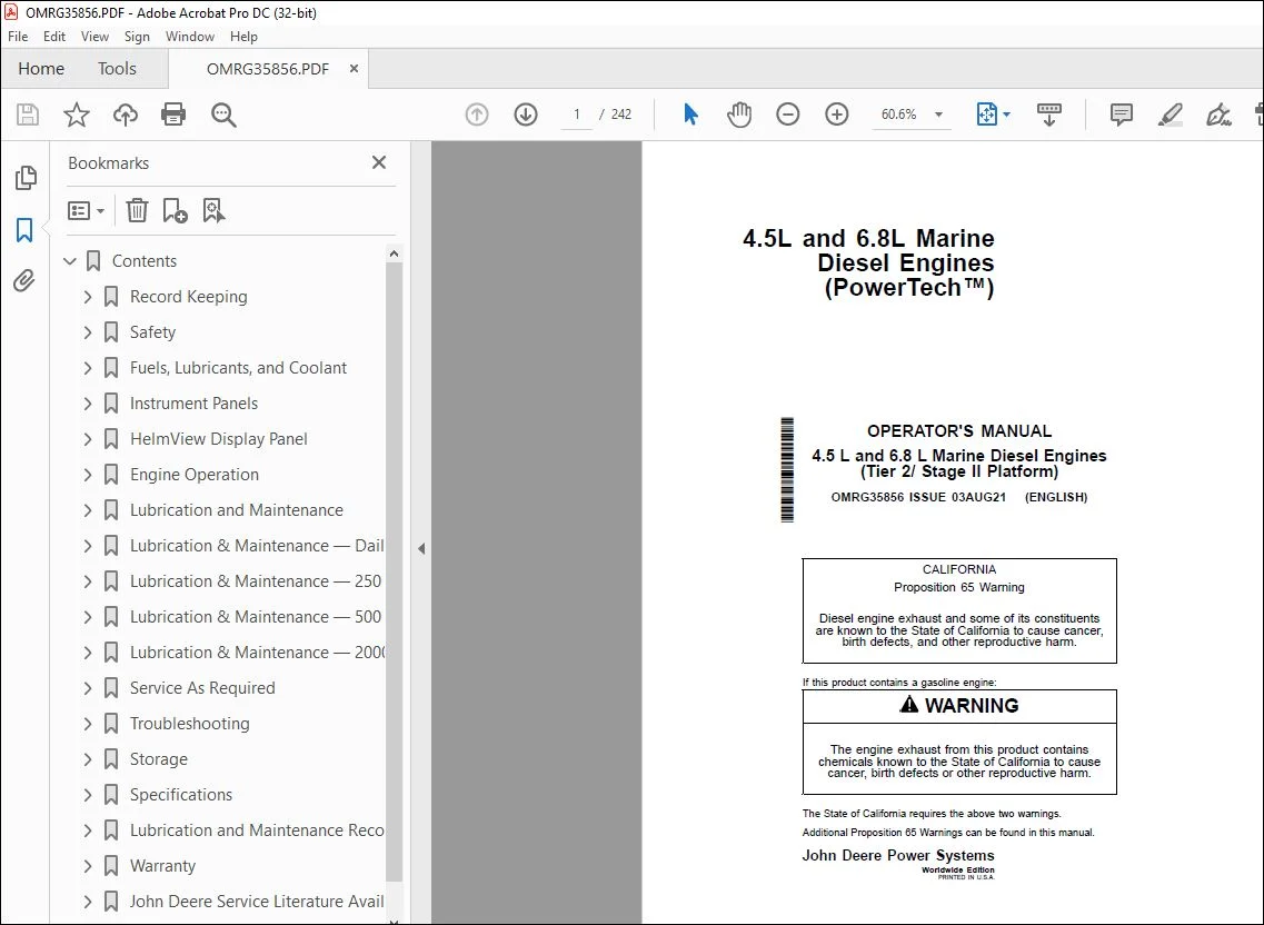
John Deere 4.5L & 6.8L Marine Diesel Engines Operator’s Manual PDF
$28.95
John Deere 4.5L & 6.8L Marine Diesel Engines (PowerTech™) Operator’s Manual – PDF DOWNLOAD
Description
John Deere 4.5L & 6.8L Marine Diesel Engines (PowerTech™) Operator’s Manual – PDF DOWNLOAD
FILE DETAILS:
John Deere 4.5L & 6.8L Marine Diesel Engines (PowerTech™) Operator’s Manual – PDF DOWNLOAD
P/N: OMRG35856_71
Language: English
Division: Construction
Product Lines: Engines
Publication Type: Operator’s Manuals
Associated Models: 4045, 6068, 4.5L, 6.8L
Series: POWERTECH
Serial: TIER 2/ STAGE II PLATFORM
Additional Information: POWERTECH™ 4045DFM70/TFM75, 6068SFM50/75, 6068TFM75/76, 6068AFM75 Marine Engines
IMAGES PREVIEW OF THE MANUAL:
TABLE OF CONTENTS:
John Deere 4.5L & 6.8L Marine Diesel Engines (PowerTech™) Operator’s Manual – PDF DOWNLOAD
Contents 9
Record Keeping 13
Engine Serial Number Plate 13
Record Engine Serial Number 13
Engine Option Codes 14
Record Fuel Injection Pump or High-Pressure Fuel Pump Model Number 16
Record Engine Control Unit (ECU) Serial Number 16
Safety 17
Recognize Safety Information 17
Understand Signal Words 17
Follow Safety Instructions 17
Replace Safety Signs 18
California Proposition 65 Warning 18
Illuminate Work Area Safely 18
Work in Clean Area 18
Use Proper Tools 19
Live With Safety 19
Prevent Machine Runaway 19
Handle Fuel Safely—Avoid Fires 20
Prepare for Emergencies 20
Handle Starting Fluid Safely 20
In Case of Fire 21
Handle Fluids Safely—Avoid Fires 21
Avoid Static Electricity Risk When Refueling 22
Service Machines Safely 22
Wear Protective Clothing 22
Protect Against Noise 23
Handling Batteries Safely 23
Prevent Acid Burns 24
Stay Clear of Rotating Drivelines 24
Install All Guards 25
Practice Safe Maintenance 25
Remove Paint Before Welding or Heating 26
Avoid Heating Near Pressurized Fluid Lines 26
Avoid High-Pressure Fluids 26
Do Not Open High-Pressure Fuel System 27
Protect Against High Pressure Spray 27
Prevent Battery Explosions 27
Avoid Hot Exhaust 28
Work In Ventilated Area 28
Service Cooling System Safely 28
Decommissioning — Proper Recycling and Disposal of Fluids and Components 29
Fuels, Lubricants, and Coolant 30
Diesel Fuel 30
Supplemental Diesel Fuel Additives 31
Lubricity of Diesel Fuel 31
Handling and Storing Diesel Fuel 31
Biodiesel Fuel 32
Testing Diesel Fuel 33
Fuel Filters 33
Minimizing the Effect of Cold Weather on Diesel Engines 34
Diesel Engine Break-In Oil — Non-Emissions Certified and Certified Tier 1, Tier 2, Tier 3, Stage I, Stage II, and Stage III 35
Diesel Engine Oil — Marine Engines 36
Engine Oil and Filter Service Intervals — Tier 2 and Stage II — Marine Engines 37
Mixing of Lubricants 37
Alternative and Synthetic Lubricants 38
Lubricant Storage 38
Oil Filters 38
Diesel Engine Coolant (engine with wet sleeve cylinder liners) 39
Water Quality for Mixing with Coolant Concentrate 40
Operating in Warm Temperature Climates 40
Testing Coolant Freeze Point 41
Disposing of Coolant 41
Instrument Panels 42
Sea Trials for Performance and Warranty 42
John Deere Instrument (Gauge) Panel (Mechanically Controlled 4045DFM70 Engines Only) 43
John Deere Instrument (Gauge) Panel (Electronically Controlled Engines) 46
John Deere Instrument (Gauge) Panel (Electronically Controlled Engines) (Continued) 47
Optional Electronic Displays to Monitor Engine and Navigation 48
PV101 Instrument Panels 49
PV101 Diagnostic Gauge — Using 51
PV101 Diagnostic Gauge — Main Menu 52
PV101 Diagnostic Gauge — Essential Menus 53
DG14 Diagnostic Gauge — Using 53
DG14 Diagnostic Gauge — Main Menu 54
DG14 Diagnostic Gauge — Essential Menus 55
PV480 Instrument Panel 56
PV480 Diagnostic Gauge — Using 57
PV480 Diagnostic Gauge — Main Menu 58
PV480 Diagnostic Gauge — Essential Menus 59
Main Menu Navigation 59
Engine Configuration Data 61
Accessing Stored Diagnostic Trouble Codes 63
Accessing Active Diagnostic Trouble Codes 65
Engine Shutdown Diagnostic Trouble Codes 67
Adjusting Backlighting 68
Adjusting Contrast 70
Selecting Units Of Measurement 72
Setup 1-Up Display 74
Setup 4-Up Display 79
HelmView Display Panel 84
Product Information 84
Display Features 84
Navigation 85
Setting up your display for the first time 87
Product Features 89
Reprogramming the Display 96
Group Numbers 97
Engine Operation 98
Normal Engine Operation 98
Marine Break-In Service 99
Auxiliary Gear Drive Limitations 101
Generator Set Power Units 101
Starting the Engine 102
Warming Engine 104
Idling Engine 104
Engaging And Disengaging Front PTO (If Equipped) 105
Cold Weather Operation 105
Stopping the Engine 106
Using a Booster Battery or Charger 107
Welding Near Electronic Control Units 108
Keep Electronic Control Unit Connectors Clean 108
Lubrication and Maintenance 109
Required Emission-Related Information 109
Observe Service Intervals 109
Use Correct Fuels, Lubricants, and Coolant 110
Lubrication and Maintenance Service Interval Chart—Propulsion and Prime Power Units 111
Lubrication and Maintenance Service Interval Chart—Standby Generator Sets 112
Lubrication & Maintenance — Daily 113
Daily Prestarting Checks 113
Lubrication & Maintenance — 250 Hours/6 Months 116
Changing Engine Oil and Replacing Oil Filter 116
Servicing Fire Extinguisher 118
Servicing Battery 119
Inspect and Replacing Zinc Plugs 120
Checking Belt Wear (Manual Tensioner) 121
Checking Engine Mounts 122
Lubrication & Maintenance — 500 Hours/12 Months 123
Replace Crankcase Vent Filter (If Equipped) 123
Checking Closed Crankcase Vent System (If Equipped) 124
Checking Air Intake System 125
Replacing Final Fuel Filter/Water Separator 126
Replacing Primary Fuel Filter Element 127
Checking Belt Tensioner Spring Tension and Belt Wear (Automatic Tensioner) 128
Checking Cooling System 130
Replenishing Supplemental Coolant Additives (SCAs) Between Coolant Changes 131
Testing Diesel Engine Coolant 132
Remove, Inspect and Clean Engine Heat Exchanger Core 132
Install Heat Exchanger Core 136
Remove, Inspect and Clean EngineAftercooler Core (6068SFM50) 138
Remove, Inspect and Clean EngineAftercooler Core (6068SFM75) 139
Install Aftercooler Core (6068SFM50) 140
Install Aftercooler Core (6068SFM75) 141
Pressure Testing Cooling System 142
Checking and Adjusting Engine Speeds 143
Checking Engine Electrical Ground Connections 143
Lubrication & Maintenance — 2000 Hours/24 Months 144
Checking and Adjusting Engine Valve Clearance (Except 6068SFM75 and 6068AFM75) 144
Checking and Adjusting Engine Valve Clearance (6068SFM75 and 6068AFM75) 149
Flushing And Refilling Cooling System 150
Inspecting Thermostats and Testing Opening Temperature 152
Checking Crankshaft Vibration Damper (6-Cylinder Engine Only) 153
Inspect and Repair Sea Water Pump (Except 6068SFM50/75 and 6068AFM75) 153
Inspect And Repair Sea Water Pump (6068SFM50/75 and 6068AFM75) 156
Service As Required 157
Additional Service Information 157
Do Not Modify Fuel System 157
Adding Coolant 158
Pre-Start Cleaning Guide 158
Replacing Dry Air Cleaner Element (Enclosed Element Installations) 159
Servicing Air Cleaner Filter Element 160
Replacing Air Cleaner Filter Element 162
Replacing Alternator Belt (With Automatic Tensioner) 163
Replacing Alternator Belt (With Manual Tensioner) 164
Check Front Power Take-Off (PTO) 164
Drain Water From Fuel Filter 165
Bleeding the Fuel System—Engines With Mechanical Fuel Supply Pump 165
Bleeding Fuel System—Engines With Electric Fuel Supply Pump 167
Bleeding Fuel System—6068SFM75/AFM75 168
Troubleshooting 169
General Troubleshooting Information 169
Precautions for Welding 170
Precautions For Welding On Vessels Equipped With Electronic Engine Control Unit (ECU) 170
Transition Harness Wiring Diagram 172
Propulsion Engine Wiring Harness – Mechanically Controlled Engine (4045DFM70) 176
Propulsion Engine Wiring Harness – Mechanically Controlled Engine (4045DFM70) 177
Propulsion Engine Instrument Panel – Mechanically Controlled Engine (4045DFM70) 178
Electronically Controlled Engine Electrical System Layout — 6068SFM50 Shown 179
Transition Harness Wiring Diagram 182
Wiring Diagram for John Deere Main Station (Wheel House) Instrument Panel – Electronically Controlled Engine 186
Wiring Diagram for John Deere Main Station (Wheel House) Instrument Panel – Electronically Controlled Engine – Cont’d 187
Wiring Diagram for John Deere Optional Fly Bridge Instrument Panel – Electronically Controlled Engine 188
6068TFM75 and 6068SFM50 Marine Electronic Control System Wiring Diagram 190
6068TFM75 and 6068SFM50 Marine Electronic Control System Wiring Diagram – Cont’d 191
6068SFM75 / AFM75 Marine Electronic Control System Wiring Diagram 192
6068SFM75 / AFM75 Marine Electronic Control System Wiring Diagram – Continued 194
6068SFM75 / AFM75 Marine Electronic Control System Wiring Diagram – Continued 196
Engine Coolant and Sea Water Flow For Heat Exchanger Engines (Except 6068SFM50/75 and 6068AFM75) 198
Engine Coolant and Sea Water Flow (6068SFM50) 200
Engine Troubleshooting 202
Electrical Troubleshooting 207
Blink Code Method for Retrieving Diagnostic Trouble Codes (Except 6068SFM75 and 6068AFM75) 208
Instrument Panel Method for Retrieving Diagnostic Trouble Codes 209
Listing Of Diagnostic Trouble Codes (DTC) 210
Intermittent Fault Diagnostics 216
Storage 217
Engine Storage Guidelines 217
Preparing Engine for Long-Term Storage 217
Removing Engine from Long-Term Storage 218
Specifications 219
General Engine Specifications—4 5 L Engines 219
General Engine Specifications—6 8 L Engines 220
Engine Power And Speed Specifications 221
Engine Crankcase Oil Fill Quantities 222
Unified Inch Bolt and Screw Torque Values 223
Metric Bolt and Screw Torque Values 224
Lubrication and Maintenance Records 225
Using Lubrication and Maintenance Records 225
Daily (Prestarting) Service 225
250 Hour-6 Month Service 225
500 Hour/12 Month Service 226
2000 Hour-24 Month Service 227
Service As Required 227
Warranty 228
John Deere Warranty in OEM Applications 228
Emissions Control System Certification Label 231
U S Marine Compression-Ignition Engine Emission Control Warranty Statement 232
European Union (EU) Declaration of Emissions Conformity 233
John Deere Service Literature Available 234
Technical Information 234
Page Number 9
Section 01 13
Section 05 17
Section 10 30
Section 15 42
Section 20 84
Section 25 98
Section 30 109
Section 35 113
Section 40 116
Section 45 123
Section 50 144
Section 55 157
Section 60 169
Section 65 217
Section 70 219
Section 75 225
Section 80 228
Section 85 234
S.V 04/24