
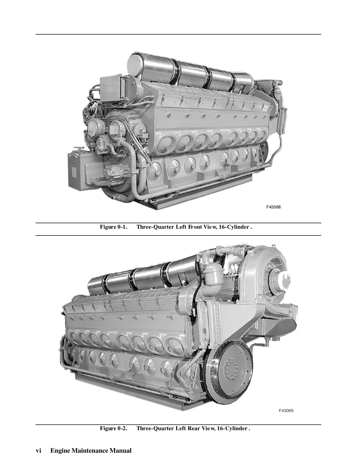
710G3B Series 4000-4500 HP 16-Cylinder Diesel Locomotive Engine Maintenance Manual – 2009
Original price was: $39.95.$24.95Current price is: $24.95.
First Edition, October 2009 service and maintenance manual for the 16-cylinder 710G3B series diesel locomotive engine rated at 4000/4500 HP. Covers cylinder head and accessories, piston assembly and connecting rods, cylinder liners, crankshaft and gear trains, air intake and exhaust, lubrication, cooling, fuel, controls, governor, protective devices, starting system, troubleshooting, and metric conversion.
Description
710G3B Series 4000-4500 HP Diesel Locomotive Engine Maintenance Manual
This is the complete 710G3B Series 4000-4500 HP 16-Cylinder Diesel Locomotive Engine Maintenance Manual, First Edition, October 2009, published by Diesel Locomotive Works, Varanasi. It is the reference document for the maintenance, overhaul, disassembly, inspection, and reassembly of the 16-cylinder 710G3B series two-cycle turbocharged diesel engine rated at 4000/4500 HP. Every procedure is written around the actual engine hardware — torque values, dimensional limits, measurement points, and tooling — so the manual serves as a working document on the shop floor, not a generic overview.
File Details
- Manual type: Engine Maintenance Manual
- Engine series: 710G3B, 16-cylinder, 4000/4500 HP
- Publisher: Diesel Locomotive Works, Varanasi
- Edition: First Edition, October 2009
- Language: English
- File format: PDF
- Page count: 497
Chapters Covered
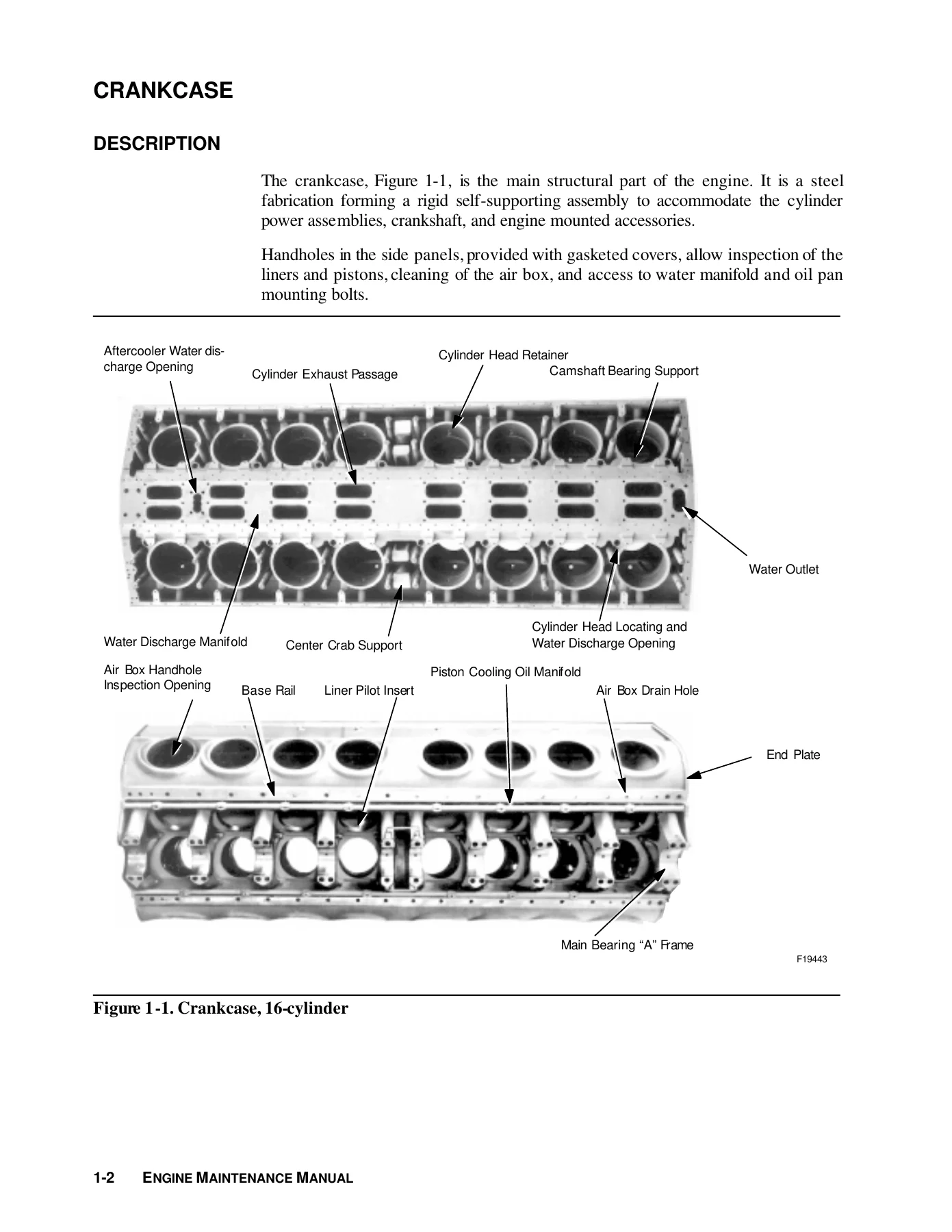
- Section 1 – Crankcase and Oil Pan: crankcase description, cleaning, inspection, lower liner bore insert application and removal, main bearing bolting systems, main bearing caps, crankcase-to-oil-pan seal, air box drains, top deck head frame and cover
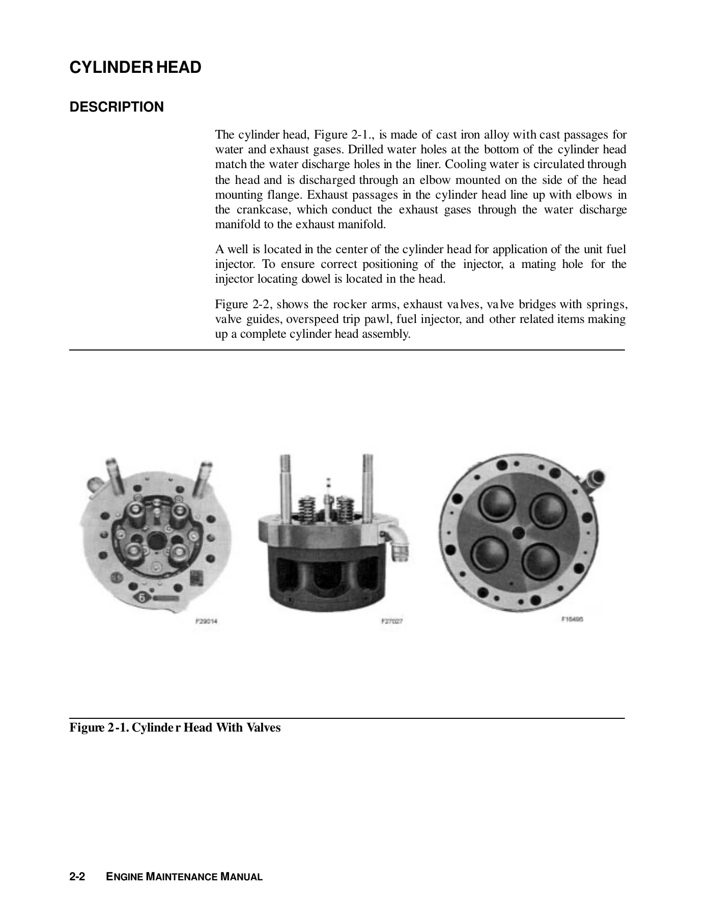
- Section 2 – Cylinder Head and Accessories: cylinder head description, cleaning, leak test, inspection, rebuild, injector hole rework, fireface and flange refinishing, valve seat reconditioning, exhaust valves, valve springs, seats and locks, valve bridge and hydraulic lash adjuster, rocker arm assembly, rocker arm support, cylinder test valves, cylinder head seat ring
- Section 3 – Piston Assembly and Connecting Rods: piston carrier and thrust washer, piston pin, insert bearing, piston and rod inspection, disassembly, cleaning, inspection, connecting rod assembly, fork rod, blade rod, fork rod basket halves, connecting rod bearings, service data and equipment list
- Section 4 – Cylinder Liner: liner description, water inlet deflector, measuring liners for wear, oversize liners, wear ridge removal, honing procedure, cleaning, marking used liners and pistons in stock
- Section 5 – Cylinder Power Assembly: component-by-component removal, unit removal, component-by-component installation, unit installation, power assembly packaging, adjusting hydraulic lash adjusters, timing the injectors, crab nut torque wrenches
- Section 6 – Crankshaft Assembly and Accessory Drive Gear Train: crankshaft, main bearings, thrust collar, gear type torsional damper, accessory drive gear train, accessory drive gear, governor drive gear and stubshaft, accessory drive housing application and alignment, accessory drive coupling, ring gear and coupling disc, magnetic speed pickup
- Section 7 – Camshaft Gear Train, Auxiliary Drive, and Camshaft Assemblies: camshaft drive gears, clutch drive gear assembly, clutch doweling assembly, No. 1 idler gear, idler gear stubshaft assembly, crankshaft gear, camshaft gear train assembly, auxiliary drive assembly, camshaft assemblies, exhaust valve timing
- Section 8 – Air Intake and Exhaust Systems: turbocharger removal, preparation for installation, installation, final assembly, starting the engine, exhaust manifold
- Section 9 – Lubricating Oil System: main lubricating oil system, piston cooling oil system, scavenging oil system, oil gauge, main lubricating oil pressure, piston cooling oil pressure, main lube oil and piston cooling oil manifold, lube oil pressure relief valve, piston cooling oil pipe, checking oil viscosity, changing oil, oil strainer housing, lube oil separator, main lube oil and piston cooling oil pumps, scavenging oil pump, turbocharger oil filter, soak back oil system, prelubrication of engines
- Section 10 – Cooling System: cooling system piping, water leaks, aftercooler removal, cleaning, core replacement, installation, water pumps, pump disassembly, pump assembly, installing pump
- Section 11 – Fuel Oil System: mechanical unit injector (MUI) description, MUI injector installation, timing the MUI injector, sticking MUI injectors, servicing MUI injectors, MUI injector tester, MUI injector linkage, setting MUI injector racks, fuel filter assembly
- Section 12 – Engine Controls: (Section 12A) governor description, operation, compensation, engine speed control, engine shutdown, air pressure sensor assembly, fuel limiter, rebalancer rocker arm stop screw, load regulator pilot valve, integral oil filled vane servo load regulator, overriding solenoid, low oil pressure shutdown, governor drive assembly; (Section 12B) EMDEC System
- Section 13 – Protective Devices: low oil pressure shutdown, low water and crankcase pressure detector assembly, overspeed control, mechanical overspeed trip, adjusting mechanical overspeed trip, hot oil temperature shutdown
- Section 14 – Starting System: electric starting motor(s), inspection, no load test, disassembly, cleaning, armature servicing, field coil checks, bearing replacement, assembly, pinion clearance
- Section 15 – Troubleshooting: starting system fault tables, fuel oil system, lubricating oil system, cooling system, engine performance, running turbocharger, engine with failed turbocharger, one revolution inspection charts, liner/piston visual inspection guide, governor and governor related troubleshooting
- Appendix A – Metric Conversion: length, area, volume, mass, force, temperature, torque, power, pressure, energy, light, fuel performance, velocity conversion tables
IMAGES PREVIEW
What This 710G3B Engine Manual Gives a Technician
The manual is structured around the way the engine is actually worked on. Sections 1 through 4 build up the major stationary and reciprocating components — crankcase, cylinder head, piston assembly, connecting rods, and cylinder liner — with their individual qualification procedures, wear limits, and rebuild steps. Section 5 assembles those components into the cylinder power assembly and covers both component-by-component and unit removal/installation, plus hydraulic lash adjuster setting and injector timing. Sections 6 and 7 cover the two gear trains: the accessory drive at the front and the camshaft/clutch drive at the rear, including the gear type torsional damper, accessory drive coupling, ring gear and coupling disc, clutch drive gear assembly, and exhaust valve timing. Sections 8 through 11 handle the support systems — air intake and exhaust with the turbocharger and exhaust manifold, the lubricating oil system with its pumps, strainer housing, lube oil separator, turbocharger oil filter and soak back system, the cooling system with aftercooler and water pumps, and the fuel oil system built around the Mechanical Unit Injector (MUI) with injector tester and rack setting procedures. Sections 12A and 12B cover the governor and the EMDEC system. Section 13 documents the protective devices, Section 14 the electric starting motors, and Section 15 provides the troubleshooting tables that tie all of the above together.
How the 710G3B Series Engine is Covered
The 710G3B Series 4000-4500 HP Diesel Locomotive Engine Maintenance Manual treats the 16-cylinder version as the reference platform. Engine specifications in the Service Data pages include a 230.19 mm (9-1/16 in) bore, 279.4 mm (11 in) stroke, 11,635 cm³ (710 cu in) displacement per cylinder, 16:1 compression ratio, 45° angle between banks, counterclockwise rotation facing rear, and firing order 1,8,9,16,3,6,11,14,4,5,12,13,2,7,10,15. Output is listed at 4000/4500 HP, with full speed at 904/954 RPM and idle speeds of 269/270 RPM. Weights, torque values, and equipment lists are provided throughout for the parts being serviced.
Beyond the numbered chapters, the manual contains Service Data pages at the end of most sections. These gather references, specifications, and equipment lists into a single location for each system so the technician does not have to search across the whole document. Clearance and dimensional limits are defined with minimum, maximum, and tolerance measurements, and the manual explains how those service limits are meant to be used — as requalification limits at overhaul, not as a basis for changing components on a running engine.
Diagnostics and Troubleshooting Support
Section 15 is built for the technician who has a locomotive that will not start, is misfiring, knocking, vibrating, emitting smoke, or shutting down unexpectedly. Tables walk through starting system faults, fuel oil system faults, lubricating oil system faults, cooling system faults, and engine performance faults — each fault condition mapped to possible causes and recommended checks. The section also includes the “One Revolution” inspection sequence charts that allow air box inspection of power assembly components during a single revolution of the crankshaft, plus the liner/piston visual inspection guide with defined terms for scoring, scuffing, and wear. Governor and governor-related troubleshooting tables close out Section 15.
Why This Manual Matters
The 710G3B is a turbocharged two-cycle V-type engine with unit injection, a positive scavenging air system, and a gear-driven turbocharger that disengages through an overrunning clutch once exhaust heat energy is sufficient to drive the turbine alone. Getting one of these engines right — right torque, right clearance, right timing, right lash — depends on having the procedures and limits in front of you. This manual provides them, along with the tooling part numbers needed to do the work correctly. When a power assembly is being removed, a cylinder head rebuilt, a set of injector racks set, or a governor compensation adjusted, the numbers and procedures in this document are what keep the engine serviceable and prevent a small error from turning into a failed component.
Instant PDF Delivery
The 710G3B Series 4000-4500 HP 16-Cylinder Diesel Locomotive Engine Maintenance Manual is delivered as an instant PDF download — no shipping, no waiting. Open it on any device and print the pages you need for the job at hand, whether that is a single cylinder head refresh or a full power assembly change-out.
Reviews
There are no reviews yet.